
Use and Care Manual


-34-
Model G0716 (Mfg. Since 2/18)
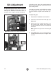
Gib Adjustment
The gibs apply pressure to the slides of the sand-
ing head (see Figures 32–33). This allows the
sanding head assembly to accurately move up
and down when using the elevation handwheel.
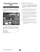
Figure 32. Location of rear slide and lock nut.
Slide
Lock
Nut
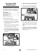
Figure 33. Location of rear gib and cap screws.
Gib
(1 of 2)
Cap
Screws
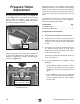
If the gibs are too loose, the sanding drum will
deflect up during operation, which will result in
poor sanding results.
If the gibs are too tight, it will be difficult to adjust
the sanding drum elevation, which will cause
excessive wear on the parts of the elevation sys-
tem.
To adjust the gibs:
1. DISCONNECT SANDER FROM POWER!
2. Loosen the center lock nut on both gibs (see
Figure 32).
3. Adjust each of the six gib cap screws in or
out in small, equal amounts, then rotate the
elevation handwheel to test the sanding head
movement.
Note: Tighten the cap screws to increase gib
pressure.
4. Repeat Step 3 until you are satisfied with the
sanding head movement, then re-tighten both
lock nuts.