MODEL G0765 7" X 14" BENCHTOP LATHE OWNER'S MANUAL (For models manufactured since 5/15) COPYRIGHT © MARCH, 2014 BY GRIZZLY INDUSTRIAL, INC. REVISED FEBRUARY, 2018 (HE) WARNING: NO PORTION OF THIS MANUAL MAY BE REPRODUCED IN ANY SHAPE OR FORM WITHOUT THE WRITTEN APPROVAL OF GRIZZLY INDUSTRIAL, INC. #BLTSDM16229 PRINTED IN CHINA V2.02.
This manual provides critical safety instructions on the proper setup, operation, maintenance, and service of this machine/tool. Save this document, refer to it often, and use it to instruct other operators. Failure to read, understand and follow the instructions in this manual may result in fire or serious personal injury—including amputation, electrocution, or death. The owner of this machine/tool is solely responsible for its safe use.
Table of Contents INTRODUCTION................................................ 2 Machine Description....................................... 2 Contact Info.................................................... 2 Manual Accuracy............................................ 2 Identification.................................................... 3 Controls & Components.................................. 4 G0765 Data Sheet.......................................... 6 SECTION 1: SAFETY....................................
INTRODUCTION Machine Description Manual Accuracy The metal lathe is used to remove material from a workpiece that is mounted to the spindle and rotated over the bed. The cutting tool is mounted alongside the bed and moved against the spinning workpiece to cut it. We are proud to provide a high-quality owner’s manual with your new machine! Typical metal lathe cutting operations include facing, turning, parting, drilling, reaming, grooving, knurling, and threading.
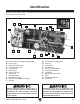
Identification Become familiar with the names and locations of the controls and features shown below to better understand the instructions in this manual. D C A B F E G I H J W K V L U T S R P Q O N M Figure 1. Model G0765 identification. A. B. C. D. E. F. G. H. I. J. K. L.
Controls & Components Carriage G H To reduce your risk of serious injury, read this entire manual BEFORE using machine. L Refer to Figures 2–6 and the following descriptions to become familiar with the basic controls of this lathe. Control Panel A B C F E D J I Figure 3. Carriage controls. G. 4-Way Tool Post: Holds up to four cutting tools at once that can be individually indexed to the workpiece. H.
Tailstock Rear Controls N M T O U P Q S R Figure 4. Tailstock controls. M. Tailstock Quill: Moves a tool or center mounted in the tailstock toward or away from the workpiece. N. Tailstock Quill Lock Lever: Secures the quill position. O. Tailstock Lock Lever: Secures tailstock in position along the bedway. P. Graduated Scale: Indicates quill movement in increments of 0.001", with one full revolution equaling 0.04" of quill travel. Figure 5. Rear controls. T.
MACHINE DATA SHEET Customer Service #: (570) 546-9663 · To Order Call: (800) 523-4777 · Fax #: (800) 438-5901 MODEL G0765 7" X 14" VARIABLE‐SPEED BENCHTOP LATHE Product Dimensions: Weight................................................................................................................................................................ 88 lbs. Width (side-to-side) x Depth (front-to-back) x Height............................................................................. 30 x 9 x 10 in.
Headstock Info Spindle Bore........................................................................................................................................... 0.78 in. Spindle Size................................................................................................................................................. 3 in. Spindle Taper............................................................................................................................................
SECTION 1: SAFETY For Your Own Safety, Read Instruction Manual Before Operating This Machine The purpose of safety symbols is to attract your attention to possible hazardous conditions. This manual uses a series of symbols and signal words intended to convey the level of importance of the safety messages. The progression of symbols is described below. Remember that safety messages by themselves do not eliminate danger and are not a substitute for proper accident prevention measures.
WEARING PROPER APPAREL. Do not wear clothing, apparel or jewelry that can become entangled in moving parts. Always tie back or cover long hair. Wear non-slip footwear to reduce risk of slipping and losing control or accidentally contacting cutting tool or moving parts. HAZARDOUS DUST. Dust created by machinery operations may cause cancer, birth defects, or long-term respiratory damage. Be aware of dust hazards associated with each workpiece material.
Additional Safety for Metal Lathes Serious injury or death can occur from getting entangled in, crushed between, or struck by rotating parts on a lathe! Unsecured tools or workpieces attached to rotating objects can also strike nearby operators with deadly force. To minimize the risk of getting hurt or killed, anyone operating this machine MUST completely heed the hazards and warnings below. CLOTHING, JEWELRY & LONG HAIR. Tie back long hair, remove jewelry, and do not wear loose clothing or gloves.
Additional Chuck Safety ENTANGLEMENT. Entanglement with a rotating chuck can lead to death, amputation, broken bones, or other serious injury. Never attempt to slow or stop the lathe chuck by hand, and always roll up long sleeves, tie back long hair, and remove any jewelry or loose apparel BEFORE operating. CHUCK SPEED RATING. Excessive spindle speeds greatly increase the risk of the workpiece or chuck being thrown from the machine with deadly force.
SECTION 2: POWER SUPPLY Availability Before installing the machine, consider the availability and proximity of the required power supply circuit. If an existing circuit does not meet the requirements for this machine, a new circuit must be installed. To minimize the risk of electrocution, fire, or equipment damage, installation work and electrical wiring must be done by an electrician or qualified service personnel in accordance with all applicable codes and standards.
Grounding & Plug Requirements This machine MUST be grounded. In the event of certain malfunctions or breakdowns, grounding reduces the risk of electric shock by providing a path of least resistance for electric current. This machine is equipped with a power cord that has an equipment-grounding wire and a grounding plug. Only insert plug into a matching receptacle (outlet) that is properly installed and grounded in accordance with all local codes and ordinances.
SECTION 3: SETUP Preparation The list below outlines the basic process of preparing your machine for operation. Specific steps are covered later in this section. SUFFOCATION HAZARD! Keep children and pets away from plastic bags or packing materials shipped with this machine. Discard immediately. The typical preparation process is as follows: 1. Unpack lathe and inventory contents of box/ crate. 2. Clean lathe and its components. 3.
Inventory The following is a list of items shipped with your machine. Before beginning setup, lay these items out and inventory them. If any non-proprietary parts are missing (e.g. a nut or a washer), we will gladly replace them; or for the sake of expediency, replacements can be obtained at your local hardware store. Installed Components (Figure 8) Qty. A. 3" Three-Jaw Chuck w/Internal Jaw Set..... 1 B. Steady Rest................................................. 1 C. 4-Way Tool Post.......................
Cleanup The unpainted surfaces of your machine are coated with a heavy-duty rust preventative that prevents corrosion during shipment and storage. This rust preventative works extremely well, but it will take a little time to clean. Be patient and do a thorough job cleaning your machine. The time you spend doing this now will give you a better appreciation for the proper care of your machine's unpainted surfaces.
Site Considerations Weight Load Physical Environment Refer to the Machine Data Sheet for the weight of your machine. Make sure that the surface upon which the machine is placed will bear the weight of the machine, additional equipment that may be installed on the machine, and the heaviest workpiece that will be used. Additionally, consider the weight of the operator and any dynamic loading that may occur when operating the machine.
Lifting & Placing HEAVY LIFT! Straining or crushing injury may occur from improperly lifting machine or some of its parts. To reduce this risk, get help from another person. With the help of another person, lift the machine to a suitable location. Assembly With the exception of the handwheel handles, the lathe is shipped fully assembled.
Test Run 2. Once assembly is complete, test run the machine to ensure it is properly connected to power and safety components are functioning correctly. Shift high/low range lever on back of lathe to LOW, and feed direction lever to neutral (see Figure 16). High/Low Range Lever If you find an unusual problem during the test run, immediately stop the machine, disconnect it from power, and fix the problem BEFORE operating the machine again.
4. Disengage half nut with lever shown in Figure 17. 6. Verify lathe is operating correctly by turning spindle direction switch to "F" position. Slowly turn variable speed dial clockwise until spindle speed display shows 100 RPM. The spindle should rotate counterclockwise— down and toward the front of the lathe. 7. Push Emergency Stop button to turn lathe OFF.
Before Before subjecting subjecting the the spindle spindle to to operational operational loads, loads, itit is essential to complete the break-in is essential to complete the break-in process. process. This This helps helps maximize maximize the the life life of of spindle spindle bearings bearings and other precision components by thoroughly and other precision components by thoroughly lubricating lubricating them them before before placing placing them them under under load. load.
SECTION 4: OPERATIONS Operation Overview The purpose of this overview is to provide the novice machine operator with a basic understanding of how the machine is used during operation, so the machine controls/components discussed later in this manual are easier to understand. Due to the generic nature of this overview, it is not intended to be an instructional guide.
Chuck & Faceplate Mounting Installation & Removal Device This lathe is equipped with an intrinsic backplate spindle nose. With this type of spindle, a chuck or faceplate is mounted directly to the backplate with hex nuts. Place a piece of plywood over the bedways to protect them from damage if a chuck or other tooling is dropped (see below). Never use spindle speeds faster than chuck RPM rating or safe limits of your workpiece.
Chuck Installation 4. To ensure accurate work, it is extremely important to make sure the spindle nose and chuck mating surfaces are clean. Even a small amount of lint or debris can affect accuracy. Insert chuck screws through mounting holes in spindle backplate, as shown in Figure 20. Make sure chuck seats firmly and evenly against backplate shoulder. Intrinsic Backplate Chuck Screw The chuck is properly installed when it is seated against the backplate shoulder (see Figure 19 below).
Scroll Chuck Clamping This 3-jaw, scroll-type chuck has an internal scrollgear that moves all jaws in unison when adjusted with the chuck key. This chuck holds cylindrical parts on-center with the axis of spindle rotation and can be rotated at high speeds if the workpiece is properly clamped and balanced. Never mix jaw types or positions to accommodate an odd-shaped workpiece. The chuck will spin out of balance and may throw the workpiece! Instead, use an independent jaw chuck or a faceplate.
To change jaw set: 1. DISCONNECT MACHINE FROM POWER! 2. Use appropriate device to protect ways (refer to Installation & Removal Device subsection). 3. Insert chuck key and turn it counterclockwise to back jaws out and remove them individually in descending order (i.e., 3, 2, 1). 4. Use mineral spirits to clean debris and grime from jaws and chuck jaw guides. 5. Apply thin coat of NLGI #2 grease to surfaces of removed jaw set. Store in safe place free from moisture and abrasives. 6.
Faceplate Refer to the prior Chuck Installation subsection for instructions on installing the faceplate. The faceplate included with your lathe can be used for a wide range of operations, including machining non-concentric workpieces, straight turning between centers, off-center turning, and boring. The tools needed for mounting a workpiece will vary depending on the type of setup you have. Machining non-concentric workpieces at high speeds could cause workpiece to be thrown from lathe with deadly force.
Tailstock The tailstock is typically used to support long workpieces at the side opposite the spindle, using a live or dead center. It can also hold a tapered drill bit (or a drill chuck with a regular drill bit) for boring holes. Unlike boring done with a drill press where the workpiece is fixed and the drill bit rotates, the drill bit in a tailstock remains stationary while the workpiece is rotated by the spindle. The entire tailstock can be repositioned and locked in place along the length of the bed.
Installing Tooling The tailstock quill accepts MT#2 tapered arbors (see the Figures below for examples). Solid End Open End Solid End Screw End Tang Tang Note: If the tooling has an open hole in the end, then a screw can be threaded into the end of the tool to provide a solid surface for the quill pin to push against when the quill is retracted for tool removal. Otherwise, removal of such tooling may be difficult. To install tooling in tailstock: 1.
Note: The marks on the offset indicator are arbitrary. For a precise offset, use a dial indicator to check quill movement while adjusting the screws. Adjustment Set Screw (1 of 2) Aligning Tailstock to Spindle Centerline This is an essential adjustment that should be verified or performed each time the tailstock is used to turn concentric workpieces between centers or immediately after offsetting the tailstock when turning a taper.
Note: As long as this dead center remains in the chuck, the point of the center will remain true to the spindle centerline. The point will have to be refinished whenever the center is removed and then returned to the chuck. 3. Install center in tailstock. 4. Attach lathe dog to test stock from Step 1, then mount it between centers, as shown in Figure below. 7. Use calipers to measure both ends of workpiece.
Centers Mounting Dead Center in Spindle Figure 36 shows the MT#2 and MT#3 dead centers included with the lathe. MT#3 Dead Center MT#2 Dead Center Figure 36. Dead centers. 1. DISCONNECT LATHE FROM POWER! 2. Thoroughly clean and dry all mating surfaces of spindle bore and center, making sure that no lint or oil remains on these surfaces. 3. Mount chuck or faceplate onto spindle, whichever is correct for your operation. 4. Insert MT#3 center into spindle bore through chuck or faceplate.
Mounting Center in Tailstock Removing Center from Tailstock The included MT#2 dead center or a live center (not included) can be used in tailstock. Mounting instructions are the same for both. Figure below shows an example photo of a dead center mounted in a tailstock. To remove the center from the quill, hold onto it with a gloved hand or shop rag, then rotate the quill handwheel counterclockwise to draw the quill back into the casting until the center releases.
Steady Rest The steady rest supports long shafts and can be mounted anywhere along the length of the bedway. Familiarize yourself with the steady rest components shown below to better understand the controls before using it. Tools Needed for Installation/Removal Qty Open-End Wrench 14mm................................... 1 Open-End Wrench 16mm................................... 1 Finger Adjustment Knob To install and use the steady rest: 1. DISCONNECT LATHE FROM POWER! 2.
Compound Rest Four-Way Tool Post The compound rest handwheel has an indirectread graduated scale. This means that the distance shown on the scale represents the actual distance the cutting tool moves. The base of the compound rest has another graduated scale used for setting the cutting tool to a specific angle. The four-way tool post is mounted on top of the compound rest and allows a maximum of four tools to be loaded simultaneously. Graduated Dial Increments................................ 0.001" (0.
Aligning Cutting Tool with Spindle Centerline For most operations, the cutting tool tip should be aligned with the spindle centerline, as illustrated below. Qty Tools Needed Hex Wrench 6mm............................................... 1 Steel Shims........................................ As Needed Cutting Tool........................................................ 1 Tailstock Center..................................................
Manual Feed Spindle Speed The cutting tool can be manually fed into the workpiece using the carriage, cross slide, and compound rest handwheels shown below. Using the correct spindle speed is important for getting safe and satisfactory results, as well as maximizing tool life. Carriage Handwheel Compound Rest Handwheel Cross Slide Handwheel Figure 45. Manual feeding controls. Carriage Handwheel Graduated Dial Increments.................................... 0.01" (0.25mm) One Full Revolution............
Setting Spindle Speed Range Configuration Example The high/low range lever shown in Figure 47, is used to select one of the two spindle speed ranges. Follow this example to gain a better understanding of how to set the spindle speed. To set spindle speed to 100 RPM: High/Low Range Lever 1. Make sure spindle is completely stopped, and shift high/low range lever to LOW, as shown in Figure 47.
Power Feed The carriage has power feed options for either threading or non-threading operations. However, this subsection only covers using the power feed option for non-threading operations. To learn how to power the carriage for threading operations, refer to Threading on Page 46. B. Feed Direction Lever: Selects carriage travel direction. The carriage moves left when feed direction lever is up, half nut lever is engaged, and spindle switch is set to "F".
Setting Power Feed Rate 8. Reposition adjuster so gears mesh, tighten adjuster hex nut, then secure gears with cap screws and flat washers removed earlier. 9. Re-install end cover. Follow the example below to better understand how to set the lathe power feed. Tools Needed: Hex Wrenches 4 & 5mm...............................1 Ea Open-End Wrenches 13 & 14mm..................1 Ea 10. Push half nut lever down to engage power feed (see Figure 53). To set power feed for 0.04 in./rev.: 1.
C (20T) End Gears Primary Threading Configuration The end gears must be correctly setup for power feed and threading. Use the photo below to identify the A, B, C, and D change gears, which are also referenced on the headstock feed rate gear chart. A (20T) D (80T) This threading configuration is used for inch and metric threading. Mesh the A, B, and D gears, as B (80T) shown in Figure 56.
End Gear Configuration Example 4. Remove end cover. Follow the example below to better understand how to configure the end gears for inch threading. 5. Loosen adjuster hex nut shown in Figure 60, pivot adjuster down, and disengage gears. Tools Needed Qty Hex Wrench 4 & 5mm...................................1 Ea Open-End Wrenches 13 & 14mm..................1 Ea A Gear To configure end gears for threading 20 TPI: 1. DISCONNECT LATHE FROM POWER! 2. Locate 20 TPI on gear chart shown in Figure 58.
8. Remove key and bushing from D gear shaft (see Figure 62). 11. Slide 40T, 65T, and 50T gears onto gear shafts (see Figure 63), making sure to reinstall key with 50T gear. Key A (40T) D (50T) B (65T) C (20 or 60T) Bushing Figure 62. D gear shaft key and bushing. Adjuster Hex Nut Figure 63. End gear placement. Remove existing B gear from keyed bushing shared with C gear. 12. Slide bushing removed in Step 8 onto 50T gear. 10. Slide 65T B gear onto keyed bushing and firmly against C gear. 13.
Threading High/Low Range Lever The following subsections describe how to use the threading controls and charts to set up the lathe for a threading operation. If you are unfamiliar with how to cut threads on a lathe, we strongly recommend that you read books, review industry trade magazines, or get formal training before attempting any threading projects.
TPI Apron Threading Controls The half nut lever engages the carriage with the leadscrew, which moves the carriage and cutting tool along the length of the workpiece for threading operations (see Figure 65). Gear Setup Thread Dial Chart A B C D 65 60 30 65 Thread Dial Disengaged Halfnut Lever Engaged Figure 65. Apron threading controls. Thread Dial The numbers on the thread dial (Figure 65) are used with the thread dial chart to show when to engage the half nut during inch threading.
TPI Divisible by 8: Use any line on the thread dial (see example in Figure 68). Dial Number TPI Dial Number Thread Dial 1, 5 1 14, 18, 22, 26, 38 7 5 3 1–8 1 16, 24, 32, 40, 48 Thread Dial 3 TPI Even TPI Not Divisible by 4 or 8: Use opposing number pairs 1 and 5 on thread dial (see example in Figure 70). 5 The following examples explain how to use the thread dial and the thread dial chart. 7 Figure 68. Any position on dial for threading TPI divisible by 8. Figure 70.
ACCESSORIES SECTION 5: ACCESSORIES Installing unapproved accessories may cause machine to malfunction, resulting in serious personal injury or machine damage. To reduce this risk, only install accessories recommended for this machine by Grizzly. D3640—Shop Fox Tool Table Plus This new, tool table plus was designed to answer customer requests for a slightly wider and taller table than our D2056 to accommodate a variety of bench-top machines.
SECTION 6: MAINTENANCE Daily, After Operations Always disconnect power to the machine before performing maintenance. Failure to do this may result in serious personal injury. Schedule Ongoing To maintain a low risk of injury and proper machine operation, if you ever observe any of the items below, shut down the machine immediately and fix the problem before continuing operations: • • • • • Loose mounting bolts or fasteners. Worn, frayed, cracked, or damaged wires. Guards or covers removed.
Lubrication The lathe has metal-to-metal sliding surfaces that require regular lubrication to maintain smooth movement and ensure long-lasting operation. Other than the lubrication points covered in this section, all other bearings are internally lubricated and sealed at the factory. Simply leave them alone unless they need to be replaced. Items Needed Qty Clean Rag ......................................... As Needed Mineral Spirits..................................... As Needed Stiff Brush................
Leadscrew & Carriage Rack Bedways Oil Type.....Grizzly SB1365 or ISO 68 Equivalent Amount............................................... As Needed Lubrication Frequency.................................. Daily Oil Type.....Grizzly SB1365 or ISO 68 Equivalent Amount............................................... As Needed Lubrication Frequency.................................. Daily Before lubricating the leadscrew and carriage rack (see Figure 76), clean them first with mineral spirits.
Machine Storage Change Gear Bushing Grease Type......................White Lithium NLGI#2 Frequency............................................... Annually Amount..................................................Thin Coat The plastic end gears do not need to be lubricated. However, we recommend lightly lubricating the B/C change gear keyed bushing with white lithium grease. Preparing Lathe for Storage 1. DISCONNECT LATHE FROM POWER! 2.
SECTION 7: SERVICE Review the troubleshooting and procedures in this section if a problem develops with your machine. If you need replacement parts or additional help with a procedure, call our Technical Support. Note: Please gather the serial number and manufacture date of your machine before calling. Troubleshooting Symptom Possible Cause Possible Solution Machine does not start or a circuit breaker trips. 1. Emergency stop button engaged or at fault. 2.
Lathe Operation Symptom Possible Cause Possible Solution Bad surface finish. 1. Wrong spindle speed or feed rate. 2. Dull tooling or wrong tool selection. 1. Adjust for appropriate spindle speed and feed rate. 2. Sharpen tooling or select a better tool for the intended operation. 3. Adjust tool height to spindle centerline (see Page 38). 4. Tighten gibs (see Page 57). 3. Tool height not at spindle centerline. 4. Too much play in gibs. Tapered tool difficult 1. Quill not fully retracted into tailstock.
Backlash Adjustment Backlash is the amount of free play felt while changing rotation directions with the handwheel. This can be adjusted on the cross slide leadscrew. Before beginning any adjustment, make sure all associated components are cleaned and lubricated and locks are loose. When adjusting backlash, tighten the components enough to remove backlash, but not so much that the components bind the leadscrew, making it hard to turn.
Gib Adjustment Compound Slide Adjustment Fasteners The goal of adjusting the gib screws is to remove sloppiness or "play" from the ways without overadjusting them to the point where they become stiff and difficult to move. In general, loose gibs cause poor finishes and tool chatter; however, over-tightened gibs cause premature wear and make it difficult to turn the handwheels. The gib adjustment process usually requires some trial-and-error.
Half Nut Adjustment Fuse Replacement The rigidity of the half nut engagement is adjusted by tightening or loosening the half nut gib screws. Adjust the half nut if it feels too loose or too tight when being engaged. Movement that is too stiff will accelerate wear. Movement that is too sloppy will produce inaccurate turning or threading results. This lathe features an on-board fuse designed to blow to protect sensitive electrical parts from thermal damage in the event of an overload.
Brush Replacement 3. Unscrew rear brush cap and carefully remove brush from motor (see Figure 87). This lathe is equipped with a universal motor that uses two carbon brushes to transmit electrical current inside the motor. These brushes are considered to be regular "wear items" or "consumables" that will need to be replaced during the life of the motor. The frequency of required replacement is often related to how much the motor is used and how hard it is pushed.
Timing Belt Tension & Replacement The timing belt transfers power from the motor to the drive pulley (see Figure 89). Tensioning Timing Belt 1. DISCONNECT LATHE FROM POWER! 2. Perform Steps 2–5 on Page 61 to remove components to access timing belt. 3. Verify belt is centered on drive pulley (see Figure 89) by hand-rotating chuck. The belt should be seated so it does not contact headstock or hang out at end of pulley.
Replacing Timing Belt 7. 1. DISCONNECT LATHE FROM POWER! 2. Remove end cover, rear motor cover, and electrical cabinet. Side Cover Gear Sensor Wheel Slide off old timing belt and install the new one, making sure that belt teeth are seated together with pulley teeth (see Figure 93). Timing Belt Inner Spanner Nut Outer Spanner Nut Speed Sensor Figure 91. Components to be removed to replace timing belt. 3.
SECTION 8: WIRING These pages are current at the time of printing. However, in the spirit of improvement, we may make changes to the electrical systems of future machines. Compare the manufacture date of your machine to the one stated in this manual, and study this section carefully. If there are differences between your machine and what is shown in this section, call Technical Support at (570) 546-9663 for assistance BEFORE making any changes to the wiring on your machine.
Control Panel Wiring 13 23 4WPLJ-2T DIGITAL READOUT 23 13 24 14 24 To Plug Page 65 14 24 J1 CON4 14 A1 KEDU KJD17B ON/OFF SWITCH Top of Control Panel 5 9 KEDU ZHA DIRECTION SWITCH Left Side 2 6 10 From Behind 1 5 9 6 2 P2 14 POWER LAMP P3 P1 12 24 10 10 FUSE VARIABLE SPEED 7 11 L2 KEDU ZHA DIRECTION SWITCH Right Side 12 8 4 From Behind 11 3 7 P1 12 12 12 11 P2 A− GND P3 P1 P3 P2 A- L2 L2 Machine Frame L2 L1 A+ L1 JD−014 REV A 09111 CIRCUIT BOARD A+ Front of C
Control Panel Wiring Photos Figure 94. G0765 wiring overview. Figure 96. Control panel wiring (top). Figure 95. Control panel wiring (bottom). Figure 97. Control panel wiring (front). -62- READ ELECTRICAL SAFETY ON PAGE 62! Model G0765 (Mfd.
Motor/Speed Sensor/ Plug Wiring MOTOR 83ZYT007 110V Figure 98. Motor wiring. Speed Sensor To Control Panel Page 63 To Control Panel Page 63 Figure 99. Speed sensor location. SPEED SENSOR To Control Panel Page 63 Wires connect on back side of circuit board Figure 100. Speed sensor wiring. Neutral Hot 110 VAC Ground Model G0765 (Mfd.
-64175 190 29 28 27 33 153 176 23 191 32 25 189 188 31 56 152 168 8 194 169 187 193 53 30 54 186 157 185 56 52 48 44 183 43 26 40 184 49 47 38 192 18 36 6 151 24 23 22 51 35 41 56 150 124 37 182 57 148 46 50 39 45 50 22 15 117 58 17 42 12 59 60 150-2 14 16 13 9 44 62 63 63 110 10 11 12 11 150-1 157 62 61 64 10 112 59 8 146 109 111 7 3 20 145 2 99 19 113 107 144 83 90 20 21 9 67 171 108 6 5 76 98 167 4 106 87 77 143 138 142 102 52 83 99 114 75 101 84 137 140 74 94 115 116 100 90 85 98 84 139 97 105 82V2
Main REF PART # DESCRIPTION 1 2 3 4 5 6 7 8 9 10 11 12 13 14 15 16 17 18 19 20 21 22 23 24 25 26 27 28 29 30 31 32 33 35 36 37 38 39 40 41 42 43 44 45 46 47 48 49 50 51 52 53 54 55 BED 3-JAW CHUCK 3" W/INTERNAL JAWS SPINDLE MT#3 STUD-DE M6-1 X 60, 15 FLAT WASHER 6MM HEX NUT M6-1 KEY 5 X 5 X 40 KEY 4 X 4 X 8 CAP SCREW M5-.8 X 10 BEARING COVER BALL BEARING 6206ZZ SPACER HEADSTOCK CASTING COMBO GEAR 21T/29T SPACER GEAR 45T SPANNER NUT SET SCREW M5-.
Main REF PART # DESCRIPTION REF PART # DESCRIPTION 113 114 115 116 117 119 123 124 125 126 127 128 129 131 133 134 135 136 137 138 139 140 141 142 143 144 145 146 148 150 150-1 150-2 151 152 153 157 158 STUD-DE M10-1.5 X 50, 15 COMPOUND LEADSCREW COMPOUND LEADSCREW BRACKET CAP SCREW M4-.7 X 14 MOTOR COVER (FRONT) HEX NUT M10-1.5 ELECTRICAL CABINET POWER CORD 18G 3W 60" 5-15 FOOT (RUBBER) CHIP TRAY LEADSCREW OUTBOARD BRACKET KEY 4 X 4 X 8 LONGITUDINAL LEADSCREW 16TPI LEADSCREW END BRACKET CAP SCREW M3-.
Steady Rest 173-5 173 173-6 173-4 173-3 173-2 173-1 173-7 173-8 173-9 173-10 REF PART # DESCRIPTION REF PART # DESCRIPTION 173 173-1 173-2 173-3 173-4 173-5 STEADY REST ASSEMBLY HEX NUT M8-1.25 LOCK WASHER 8MM STEADY REST CASTING STEADY REST FINGER ADJUSTING SCREW 173-6 173-7 173-8 173-9 173-10 P0765173-6 P0765173-7 P0765173-8 P0765173-9 P0765173-10 T-BOLT M8-1.25 X 26 HEX NUT M8-1.25 FLAT WASHER 8MM BASE CLAMP HEX BOLT M8-1.
Labels & Cosmetics (Front) 255 254 256 257 259 258 253 261 252 251 260 REF PART # DESCRIPTION REF PART # DESCRIPTION 251 252 253 254 255 256 MACHINE ID LABEL THREAD DIAL CHART LABEL READ MANUAL LABEL GLASSES/FACE SHIELD WARNING LABEL CHANGE DIRECTION NOTICE LABEL ENTANGLEMENT WARNING LABEL 257 258 259 260 261 DRO LABEL SPINDLE SPEED WARNING LABEL GRIZZLY GREEN TOUCH-UP PAINT HALF NUT LEVER LABEL DISCONNECT POWER WARNING LABEL -68- P0765251 P0765252 P0765253 P0765254 P0765255 P0765256 P07
Labels & Cosmetics (Rear) 262 255 256 254 263 264 265 REF PART # DESCRIPTION REF PART # 254 255 256 262 GLASSES/FACE SHIELD WARNING LABEL CHANGE DIRECTION NOTICE LABEL ENTANGLEMENT WARNING LABEL SPEED RANGE LABEL 263 264 265 P0765254 P0765255 P0765256 P0765262 DESCRIPTION P0765263 OUTBOARD ENTANGLE WARNING LABEL P0765264 THREAD CHART LABEL P0765265 ELECTRICITY LABEL Safety labels help reduce the risk of serious injury caused by machine hazards.
SECTION 10: APPENDIX Threading Charts Inch and metric thread charts for the Model G0765 are provided below for your reference. An inch thread chart is provided on the headstock, but a metric chart is not.
WARRANTY CARD Name _____________________________________________________________________________ Street _____________________________________________________________________________ City _______________________ State _________________________ Zip _____________________ Phone # ____________________ Email _________________________________________________ Model # ____________________ Order # _______________________ Serial # __________________ The following information is given on a voluntary basis.
FOLD ALONG DOTTED LINE Place Stamp Here GRIZZLY INDUSTRIAL, INC. P.O.
WARRANTY & RETURNS Grizzly Industrial, Inc. warrants every product it sells for a period of 1 year to the original purchaser from the date of purchase. This warranty does not apply to defects due directly or indirectly to misuse, abuse, negligence, accidents, repairs or alterations or lack of maintenance.