MODEL G0768/G0769 8" X 16" VARIABLE-SPEED LATHE & LATHE/MILL OWNER'S MANUAL (For models manufactured since 6/17) Model G0768 Model G0769 COPYRIGHT © AUGUST, 2014 BY GRIZZLY INDUSTRIAL, INC. REVISED JUNE, 2018 (HE) WARNING: NO PORTION OF THIS MANUAL MAY BE REPRODUCED IN ANY SHAPE OR FORM WITHOUT THE WRITTEN APPROVAL OF GRIZZLY INDUSTRIAL, INC. # BLTSDM16348 PRINTED IN CHINA V3.06.
This manual provides critical safety instructions on the proper setup, operation, maintenance, and service of this machine/tool. Save this document, refer to it often, and use it to instruct other operators. Failure to read, understand and follow the instructions in this manual may result in fire or serious personal injury—including amputation, electrocution, or death. The owner of this machine/tool is solely responsible for its safe use.
Table of Contents INTRODUCTION................................................ 3 Machine Description....................................... 3 Contact Info.................................................... 3 Manual Accuracy............................................ 3 Identification (G0768)..................................... 4 Identification (G0769)..................................... 5 Controls & Components.................................. 6 Headstock..................................................
SECTION 5: MILL OPERATIONS................... 60 Operation Overview...................................... 60 Removing Compound Rest........................... 61 Removing Compound Rest . .....................................61 Re-installing Compound Rest ...................................61 Headstock Movement................................... 62 Raising/Lowering Headstock......................................62 Tilting Headstock........................................................62 Table Travel.......
INTRODUCTION Machine Description Manual Accuracy The Model G0768 and G0769 share lathe features such as a 600 Watt (3 ⁄4 HP) 110V DC motor, variable-speed controls with digital RPM display, high/low spindle speed ranges, 4" 3-jaw and 4-jaw chucks, a convenient quick-lock tailstock, a 4-way turret toolpost, steady and follow rests, and reverse feed for cutting left-hand threads.
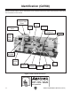
Identification (G0768) Become familiar with the names and locations of the controls and features shown below to better understand the instructions in this manual. On/Off Switch w/ Emergency Stop Button 3-Jaw Chuck Spindle Direction Switch Steady Rest 4-Way Tool Post Compound Rest Handwheel Spindle Speed RPM Display Tailstock Spindle Speed Dial Feed Direction Dial Carriage Handwheel Cross Slide Handwheel Half Nut Lever Carriage Lock Thread Dial Figure 1. Model G0768 identification.
Identification (G0769) Become familiar with the names and locations of the controls and features shown below to better understand the instructions in this manual.
Controls & Components To reduce your risk of serious injury, read this entire manual BEFORE using machine. E. ON/OFF Switch w/Emergency Stop Button: When pressed, cuts power to motor and control panel. To reset, press front tab, lift switch cover, and press green ON button. Cover must be unlatched for machine to run. F. Lathe/Mill Selector Switch (G0769 Only): Used to select between lathe mode (1), or mill mode (2).
Tailstock End Gears, Pulleys, V-Belts O P U. End Gears: The configuration of the end gears controls the leadscrew speed for power feeding, and inch and metric threading. Q N V. R V-Belts: Transfer power from motor to idler and spindle pulleys. The position of the top V-belt on idler and spindle pulleys controls spindle speed. S T Figure 5. Tailstock controls. U V N. Tailstock Quill: Uses an MT#2 taper to hold centers or other tooling, features a scale on top. O.
Milling Headstock (G0769 Only) AB X Y AC Z AD AA Figure 7. Right side milling headstock controls. X. Y. Z. Fine Downfeed Handwheel: Provides fine control over vertical spindle travel to provide Z-axis control when milling. Vertical Travel Lock Levers: Locks position of headstock to column. Downfeed Selector Knob: Selects between fine and coarse downfeed modes. Tighten to engage fine downfeed. Loosen to use coarse downfeed. Figure 8. Left side milling headstock controls. AB.
MACHINE DATA SHEET Customer Service #: (570) 546-9663 · To Order Call: (800) 523-4777 · Fax #: (800) 438-5901 MODEL G0768 8" X 16" VARIABLE‐SPEED LATHE Product Dimensions: Weight.............................................................................................................................................................. 144 lbs. Width (side-to-side) x Depth (front-to-back) x Height........................................................................... 36 x 16 x 14 in.
Headstock Info Spindle Bore......................................................................................................................................... 0.787 in. Spindle Taper............................................................................................................................................ MT#3 Number of Spindle Speeds................................................................................................................... Variable Spindle Speeds...............
MACHINE DATA SHEET Customer Service #: (570) 546-9663 · To Order Call: (800) 523-4777 · Fax #: (800) 438-5901 MODEL G0769 8" X 16" LATHE WITH MILLING HEAD Product Dimensions: Weight.............................................................................................................................................................. 234 lbs. Width (side-to-side) x Depth (front-to-back) x Height........................................................................... 36 x 20 x 34 in.
Main Specifications: Lathe Info Swing Over Bed..................................................................................................................................... 8-1/4 in. Distance Between Centers.................................................................................................................. 15-3/4 in. Swing Over Cross Slide......................................................................................................................... 4-5/8 in. Swing Over Saddle.
SECTION 1: SAFETY For Your Own Safety, Read Instruction Manual Before Operating This Machine The purpose of safety symbols is to attract your attention to possible hazardous conditions. This manual uses a series of symbols and signal words intended to convey the level of importance of the safety messages. The progression of symbols is described below. Remember that safety messages by themselves do not eliminate danger and are not a substitute for proper accident prevention measures.
WEARING PROPER APPAREL. Do not wear clothing, apparel or jewelry that can become entangled in moving parts. Always tie back or cover long hair. Wear non-slip footwear to reduce risk of slipping and losing control or accidentally contacting cutting tool or moving parts. HAZARDOUS DUST. Dust created by machinery operations may cause cancer, birth defects, or long-term respiratory damage. Be aware of dust hazards associated with each workpiece material.
Additional Safety for Metal Lathes The primary risks of operating a Metal Lathe are as follows: You can be seriously injured or killed by getting entangled in, crushed between, or struck by rotating parts on a lathe. You can be struck with deadly force by unsecured tools or workpieces attached to rotating objects. To reduce your risk of serious injury when operating this machine, completely heed and understand the following: CLOTHING, JEWELRY & LONG HAIR.
Additional Safety for Mills/Drills You can be seriously injured or killed by getting clothing, jewelry, or long hair entangled with rotating cutter/spindle. You can be severely cut or have fingers amputated from contact with rotating cutters. You can be blinded or struck by broken cutting tools, metal chips, workpieces, or adjustment tools thrown from the rotating spindle with great force.
Additional Lathe Chuck Safety ENTANGLEMENT. Entanglement with a rotating chuck can lead to death, amputation, broken bones, or other serious injury. Never attempt to slow or stop the lathe chuck by hand, and always roll up long sleeves, tie back long hair, and remove any jewelry or loose apparel BEFORE operating. CHUCK SPEED RATING. Excessive spindle speeds greatly increase the risk of the workpiece or chuck being thrown from the machine with deadly force.
SECTION 2: POWER SUPPLY Availability Before installing the machine, consider the availability and proximity of the required power supply circuit. If an existing circuit does not meet the requirements for this machine, a new circuit must be installed. To minimize the risk of electrocution, fire, or equipment damage, installation work and electrical wiring must be done by an electrician or qualified service personnel in accordance with all applicable codes and standards.
Grounding & Plug Requirements This machine MUST be grounded. In the event of certain malfunctions or breakdowns, grounding reduces the risk of electric shock by providing a path of least resistance for electric current. This machine is equipped with a power cord that has an equipment-grounding wire and a grounding plug. Only insert plug into a matching receptacle (outlet) that is properly installed and grounded in accordance with all local codes and ordinances.
SECTION 3: SETUP Setup Overview Unpacking The list below outlines the basic process of setting up the machine for first-time operation. Specific steps are covered later in this section. This machine was carefully packaged for safe transport. When unpacking, separate all enclosed items from packaging materials and inspect them for shipping damage. If items are damaged, please call us immediately at (570) 546-9663. The typical setup process is as follows: 1.
Inventory V. The following is a list of items shipped with your machine. Before beginning setup, lay these items out and inventory them. If any non-proprietary parts are missing (e.g. a nut or a washer), we will gladly replace them; or for the sake of expediency, replacements can be obtained at your local hardware store. Installed Components (Figure 10) Qty. A. 3-Jaw Chuck 4" w/Internal Jaw Set............. 1 B. Steady Rest................................................. 1 C. 4-Way Tool Post.............
Cleanup The unpainted surfaces of your machine are coated with a heavy-duty rust preventative that prevents corrosion during shipment and storage. This rust preventative works extremely well, but it will take a little time to clean. Be patient and do a thorough job cleaning your machine. The time you spend doing this now will give you a better appreciation for the proper care of your machine's unpainted surfaces.
Site Considerations Weight Load Physical Environment Refer to the Machine Data Sheet for the weight of your machine. Make sure that the surface upon which the machine is placed will bear the weight of the machine, additional equipment that may be installed on the machine, and the heaviest workpiece that will be used. Additionally, consider the weight of the operator and any dynamic loading that may occur when operating the machine.
Lifting & Placing HEAVY LIFT! Straining or crushing injury may occur from improperly lifting machine or some of its parts. To reduce this risk, get help from other people and use a forklift (or other lifting equipment) rated for weight of this machine. 4. To balance load for lifting, move tailstock and carriage to extreme right end of bedway, then lock them in place. Note: Before trying to move carriage, make sure carriage lock is loose and half nut is disengaged. 5.
Mounting Number of Mounting Holes............................. 2 Diameter of Mounting Hardware................. 5 ⁄ 16" The chip pan and lathe base have holes that allow the machine to be mounted to the optional Model T26599 Stand (see Figure 15) or a workbench. Follow these guidelines when mounting your machine to ensure safe and accurate cutting results: • Make sure stand or workbench can adequately support weight of machine and materials, and that it will not move or vibrate during operation.
Leveling Assembly With the exception of the handwheel handles, the lathe is shipped fully assembled. For accurate turning results and to prevent warping the cast iron bed and ways, the lathe bedways MUST be leveled from sideto-side and from front-to-back on both ends. Recheck the bedways 24 hours after installation, two weeks after that, and then annually to make sure they remain level.
Test Run 3. Once assembly is complete, test run the machine to ensure it is properly connected to power and safety components are functioning correctly. If you find an unusual problem during the test run, immediately stop the machine, disconnect it from power, and fix the problem BEFORE operating the machine again. The Troubleshooting table in the SERVICE section of this manual can help. G0769 Only: Set lathe/mill selector switch to "0" (see Figure 19 on Page on this page). 4.
7. Connect machine to power. The spindle speed RPM display will illuminate. 13. Rotate spindle speed dial all the way counterclockwise. 8. Press tab in on side of Emergency Stop button and lift switch cover to reset it. 14. Set lathe/mill selector switch to "2" for mill mode. 9. Turn spindle direction switch to "F" position. 15. Rotate high/low gearbox knob to low "L" (see Figure 22). G0769 Only: Set lathe/mill selector switch to "1" for lathe mode. 10.
Spindle Break-In 6. Rotate spindle speed dial all the way counterclockwise, then press Emergency Stop button. The spindle break-in procedure distributes lubrication throughout the bearings to reduce the risk of early bearing failure if there are any "dry" spots or areas where lubrication has settled in the bearings. You must complete this procedure before placing operational loads on the spindle for the first time when the machine is new or if it has been sitting idle for longer than 6 months. 7.
Recommended Adjustments 14. Rotate spindle speed dial all the way counterclockwise, then press Emergency Stop button. 15. Repeat Steps 7–10 from Lathe Spindle Break-In in a similar manner for mill. Congratulations! Mill spindle break-in is complete. The following adjustments have been made at the factory.
SECTION 4: LATHE OPERATIONS Operation Overview The purpose of this overview is to provide the novice machine operator with a basic understanding of how the machine is used during operation, so the machine controls/components discussed later in this manual are easier to understand. Due to the generic nature of this overview, it is not intended to be an instructional guide.
Chuck & Faceplate Mounting This lathe is equipped with an intrinsic backplate spindle nose. With this type of spindle, a chuck or faceplate is mounted directly to the backplate with hex nuts. Chuck Installation To ensure accurate work, it is extremely important to make sure the spindle nose and chuck mating surfaces are clean. Even a small amount of lint or debris can affect accuracy. The chuck is properly installed when it is seated against the backplate shoulder (see Figure 24).
4. Insert (3) M8-1.25 X 35 set screws through mounting holes in spindle backplate, as shown in Figure 25. Make sure chuck seats firmly and evenly against backplate shoulder. Scroll Chuck Clamping This 3-jaw, scroll-type chuck has an internal scrollgear that moves all jaws in unison when adjusted with the chuck key. This chuck holds cylindrical parts on-center with the axis of spindle rotation and can be rotated at high speeds if the workpiece is properly clamped and balanced.
Changing Jaw Set The 3-jaw scroll chuck included with the lathe features inside and outside hardened steel jaw sets (see Figure below), which move in unison to center a concentric workpiece. When installing the jaws, it is important to make sure they are installed correctly. Incorrect installation will result in jaws that do not converge evenly and are unable to securely clamp a workpiece. To change jaw set: 1. DISCONNECT MACHINE FROM POWER! 2.
4-Jaw Chuck 5. Refer to the Chuck Installation subsection for instructions on installing the 4-jaw chuck. The 4-jaw chuck features independently adjustable jaws for holding non-concentric or off-center workpieces. Each jaw can be independently removed from the chuck body and reversed for a wide range of work holding versatility.
Faceplate Refer to the prior Chuck Installation subsection for instructions on installing the faceplate. The faceplate included with your lathe can be used for a wide range of operations, including machining non-concentric workpieces, straight turning between centers, off-center turning, and boring. The tools needed for mounting a workpiece will vary depending on the type of setup you have. Machining non-concentric workpieces at high speeds could cause workpiece to be thrown from lathe with deadly force.
Tailstock The tailstock is typically used to support long workpieces at the side opposite the spindle, using a live or dead center. It can also hold a tapered drill bit (or a drill chuck with a regular drill bit) for boring holes. Unlike boring done with a drill press where the workpiece is fixed and the drill bit rotates, the drill bit in a tailstock remains stationary while the workpiece is rotated by the spindle. The entire tailstock can be repositioned and locked in place along the length of the bed.
Installing Tooling To install tooling in tailstock: The tailstock quill accepts MT#2 tapered arbors (see the Figures below for examples). 1. With tailstock locked in place, unlock quill, then use handwheel to extend it approximately 1". 2. Thoroughly clean and dry tapered mating surfaces of quill and center, making sure no lint or oil remains on tapers. 3. With a firm and quick motion, insert tool into quill.
Tools Needed Qty Hex Wrench 4mm............................................... 1 To offset tailstock: 1. Loosen tailstock lock to release clamping pressure on top and bottom castings. 2. Rotate adjustment set screws in opposite directions for desired offset (see below).
3. Install center in tailstock. 4. Attach a lathe dog to the test stock from Step 1, then mount it between centers, as shown below. 7. Use calipers to measure both ends of the workpiece. —If test stock is thicker at tailstock end, move tailstock toward front of lathe 1⁄2 the distance of the amount of taper, as shown below. Move tailstock toward front of lathe 1/2 the amount of taper. Looking down from above. Figure 40. Example of stock mounted between the centers. 5. Turn 0.010" off stock diameter.
Centers Mounting Dead Center in Spindle Figure 43 shows the MT#2 and MT#3 dead centers included with the lathe. MT#2 Dead Center MT#3 Dead Center 1. DISCONNECT MACHINE FROM POWER! 2. Thoroughly clean and dry all mating surfaces of spindle bore and center, making sure that no lint or oil remains on these surfaces. 3. Mount chuck or faceplate onto spindle, whichever is correct for your operation. 4. Insert MT#3 center into spindle bore through chuck or faceplate.
Mounting Center in Tailstock Removing Center from Tailstock The included #2 dead center or a live center (not included) can be used in the tailstock. Mounting instructions are the same for both. The Figure below shows an example photo of a dead center mounted in a tailstock. To remove the center from the quill, hold onto it with a gloved hand or shop rag, then rotate the quill handwheel counterclockwise to draw the quill back into the casting until the center releases.
Steady Rest 7. The steady rest supports long shafts and can be mounted anywhere along the length of the bedway. Familiarize yourself with the steady rest components shown below to better understand the controls before using it. Tools Needed for Installation/Removal Qty Open-End Wrench 13mm................................... 1 Open-End Wrench 14mm...................................
Compound Rest Four-Way Tool Post The compound rest handwheel has an indirectread graduated scale. This means that the distance shown on the scale represents the actual distance the cutting tool moves. The base of the compound rest has another graduated scale used for setting the cutting tool to a specific angle. The four-way tool post is mounted on top of the compound rest and allows a maximum of four tools to be loaded simultaneously. Graduated Dial Increments................................ 0.001" (0.
Aligning Cutting Tool with Spindle Centerline For most operations, the cutting tool tip should be aligned with the spindle centerline, as illustrated below. Tools Needed Qty Tool Post T-Wrench............................................ 1 Steel Shims........................................ As Needed Cutting Tool........................................................ 1 Tailstock Center..................................................
Manual Feed Spindle Speed The cutting tool can be manually fed into the workpiece using the carriage, cross slide, and compound rest handwheels shown below. Using the correct spindle speed is important for getting safe and satisfactory results, as well as maximizing tool life.
Setting Spindle Speed Range Configuration Example One of two spindle speed ranges is selected by repositioning the top V-belt between the spindle and idler pulleys (see Figure 55). Select the A position for low (50-1000 RPM) or B position for high (100–2000 RPM) speed ranges. The V-belt diagram below is also found on the headstock. Follow this example to gain a better understanding of how to set the lathe spindle speed. 1. DISCONNECT MACHINE FROM POWER! Qty Tools Needed Hex Wrench 4mm.................
4. Move top V-belt to A position (see Figure 58) to select low speed range (50–1000 RPM). Low A Understanding Gear Charts High B This subsection explains how to understand the feed and thread charts on the headstock. If you do not understand lathe gear charts, or need a quick refresher, read this before configuring the end gears for power feeding or threading operations. Top V-Belt M Figure 58. V-belt positioned in low speed range. 5. Re-tension V-belt (refer to "Tensioning V-Belts" on Page 81).
40 A C end E 0.0037" 0.0068" A B 84 30 72 30 B Thread Charts—Display headstock gear 80 33 80 20 C D positions used for cutting various metric or inch D threads (see Figure 61). E F 80 80 F Metric Thread Chart mm AB CD EF How to Read the Feed Chart Figure 62 identifies the three available feed rates and the feed icon at the top of the feed rate chart. Feed Rate Icon in/ Feed Rates 0.40 0.50 0.60 0.70 0.80 1.00 55 60 70 57 72 80 80 30 70 33 53 30 60 40 40 30 40 33 80 80 80 80 80 70 1.25 1.50 1.
in/ gears in two posiEach shaft has room to mount tions—forward and rear (see Figure 64). 40 0.0037" 0.0068" A B 84 30 72 30 B C D 20 80 33 80 D 80 E F 80 F A C How to Read the Thread Charts Figure 66 identifies the charts to use when setting carriage feed movement for metric or inch threading. E Blank Area Indicates Spacer (Not Shown) Rear mm Metric Icon Indicating Thread Pitch 0.40 0.50 0.60 0.70 0.80 1.00 A B 55 60 70 57 72 80 C D 80 30 70 33 53 30 60 40 40 30 40 33 E F 80 80 80 80 80 70 1.
Each shaft has room to mount gears in two positions—forward and rear (see Figure 69). The lines shown between the numbers in Figure 70 indicate which gears should be in mesh.
Primary Threading Configuration Configuring End Gears This threading configuration is used for inch and metric threading. Mesh the A and C, and D and F gears, as shown in Figure 72. The A/B and C/D change gears each share a keyed bushing. A spacer (E) is installed on the lower shaft in front of the F gear. Follow the example below to understand how to change the gears from the factory set power feed configuration to the primary inch threading in/ configuration.
5. Loosen adjuster cap screw shown in Figure 75, and pivot adjuster down to disengage gears. Remove keyed spacer from lower gear shaft (see Figure 77). Keyed Spacer Adjuster Gear Shafts 9. Hex Nut & E-Clips Shaft Hex Nut & Flat Washer Adjuster Cap Screw Figure 75. Adjuster cap screw location. 6. Remove hex nuts, e-clips, and flat washer that secure gears (see Figure 75). 7. Loosen top and bottom gear shafts to make it easier to remove gears in following steps. 8.
12. Remove 20T gear with keyed bushing from 80T gear (see Figure 80). 16. Thread short end of 80T/60 gear shaft into T-nut on adjuster until finger tight (see Figure 83). Keyed Bushing 80T Gear T-Nut 20T Gear Figure 80. 20T gear removed from 80T gear. 13. Remove keyed bushing from 20T gear. 14. Connect 80T and 60T gear with keyed bushing, as shown in Figure 81. The 80T gear hub faces out; the 60T gear hub faces the 80T gear. 60T Gear Bushing Hub Figure 83. 80T/60T gear threaded onto T-nut. 17.
Power Feed 20. Re-install e-clips and hex nuts onto middle and top gear shafts. 21. Adjust lash between meshed gears so it is approximately 0.003", then tighten gear shafts and fasteners. 22. Swing adjuster up and mesh 53T gear with 40T spindle gear (see Figure 86). The carriage has power feed (or automatic feed) options for threading or non-threading operations. This section describes how to use the power feed option for non-threading operations.
B. Feed Rate Chart: Displays end gear settings for selected feed rate (see Figure 88). D. Half Nut Lever: Engages/disengages half nut for power feed operations. in/ D 40 0.0037" 0.0068" A B 84 30 72 30 B C D 20 80 33 80 D 80 E F 80 F A C E Figure 90. Half nut lever. Figure 88. Feed mmchart. C. Feed Direction carriage 0.40 0.50Dial: 0.60 Selects 0.70 0.80 1.
3. Gather the required A–F change gears: 84T, 30T, 20T and two 80T gears, based upon the chart in Figure 91. 8. Adjust lash between meshed gears so it is approximately 0.003", then tighten the gear shafts. 4. Remove end cover. 9. Swing the adjuster up and mesh the 84T gear with the spindle gear. 5. Loosen adjuster cap screw shown in Figure 92, and pivot adjuster down to disengage gears. 10. Secure the adjuster cap screw. 11. Re-install end gear cover.
To set lathe to thread 20 TPI right-hand threads: 1. Configure gears as instructed in End Gear Configuration Example on Page 53. 2. Place the top V-belt in the A position for low (50-1000 RPM), as shown in Figure 94. Apron Threading Controls The half nut lever engages the carriage with the leadscrew, which moves the carriage and cutting tool along the length of the workpiece for threading operations (see Figure 96).
Figure 97. Thread dial chart. Any TPI: For threading any TPI, use only the number 1 on the thread dial (see the example in Figure 98). Note: You can choose to use only the number 1 to cut any thread if you do not want to use the chart, or if you forget any of the following rules. 7 1 Figure 98. Thread dial position for any numbered TPI. Model G0768/G0769 (Mfd. Since 6/17) 1 Figure 100. Any numbered line on dial for threading even numbered TPI.
SECTION 5: MILL OPERATIONS Operation Overview The purpose of this overview is to provide the novice machine operator with a basic understanding of how the machine is used during operation, so the machine controls/components discussed later in this manual are easier to understand. Due to the generic nature of this overview, it is not intended to be an instructional guide.
Removing Compound Rest The compound rest and tool post must be removed before milling/drilling so the cross slide table can be used as the milling table. Re-installing Compound Rest Align compound rest with swivel base mounting holes and nut (see Figure 103), then secure with cap screws previously removed. Note: While re-installing compound rest, use a 3mm hex wrench to press swivel base up from underneath and keep it from sliding back down into cross slide. Tools Needed Qty Hex Wrench 3mm................
Headstock Movement Tilting Headstock Tools Needed Qty Wrench 16mm.................................................... 1 Wrench 14mm.................................................... 1 The milling headstock moves in the following ways: • • Travels up and down the column (Z-axis). Tilts 45° left or right relative to the table. To tilt headstock: 1. DISCONNECT MACHINE FROM POWER! 2. Support headstock with one hand, then loosen headstock center bolt and angle lock nut (see Figure 106).
Table Travel The cross slide table travels in two directions, as illustrated in Figure 107: • • X-axis (longitudinal) Y-axis (cross) X-Axis or Longitudinal Travel (Left & Right) Y-Axis or Cross Travel (In & Out) Figure 107. Possible directions of cross slide travel. Carriage Handwheel (X-Axis) Graduated Dial Increments.................................... 0.01" (0.25mm) One Full Revolution........................... 1" (25.4mm) Use the carriage handwheel to move the carriage left or right along the bed.
Using Spindle Downfeed Controls The Model G0769 features two different types of spindle downfeed controls: coarse and fine, as shown in Figure 109. Fine Downfeed Handwheel Coarse Downfeed Handle Fine Downfeed Fine downfeed is typically used for milling applications, because the spindle only moves up or down when the fine downfeed handwheel (see Figure 109) is rotated (there is no automatic spindle return to the top position, as with the coarse downfeed controls).
Installing/Removing Tooling 3. Insert tooling into spindle until in contacts drawbar. 4. Working from top, thread drawbar by hand into tooling until it is snug (see Figure 112). The Model G0769 includes a 1⁄ 2" drill chuck with MT#2 arbor (see Figure 110). Figure 112. Threading drawbar into tooling. Figure 110. ⁄2" chuck joined with MT#2 arbor. 1 Cutting tools are sharp and can easily cause cutting injuries. Always protect your hands with leather gloves or shop rags when handling cutting tools. 5.
Removing Tooling 5. Tools Needed Qty Wrench 8mm...................................................... 1 Wrench 17mm.................................................... 1 Wrench 25mm.................................................... 1 Brass Hammer................................................... 1 Tap top of drawbar with hammer to unseat taper (see Figure 114). To remove tooling: 1. DISCONNECT MACHINE FROM POWER! 2. Remove drawbar cap. 3.
Spindle Speed Using the correct spindle speed is important for safe and satisfactory results, as well as maximizing tool life. Setting Spindle Speed 1. Rotate spindle speed dial all the way counterclockwise to set spindle speed to lowest value. 2. Rotate high/low gearbox knob (see Figure 116) to either “L” (spindle speeds 50–100 RPM) or “H” (spindle speeds 100–2000 RPM).
ACCESSORIES SECTION 6: ACCESSORIES Installing unapproved accessories may cause machine to malfunction, resulting in serious personal injury or machine damage. To reduce this risk, only install accessories recommended for this machine by Grizzly. T26599—Optional Stand for G0768/G0769 Size: 291⁄2" W x 32" H x 16" D • • Drawers: 12" W x 8" H x 12" D NOTICE Refer to our website or latest catalog for additional recommended accessories. T25206—11 Pc. Carbide Bit Set 5⁄16" This 11-Pc.
G9361—Heavy-Duty Triple Bearing Live Center MT#2 This Triple Bearing Live Center is hardened to 61-65 Rockwell and has a unique head driving mechanism that prevents dust, chips, and coolant from entering the internal workings. Made with precision, high-quality bearings, this live center has an accuracy of 0.0003". H7991—Mini Mag Base Indicator Set Set features a 7 Jewel indicator with 0.0005" resolution.
T10253—2" Mini Self-Centering Vise with Swivel Base Ideal for holding small parts and model making. Has self-centering jaws and adjustable gib on a dovetailed way. 21⁄16" jaw opening, 2" jaw width, 25⁄8" crank handle, and base swivels 360°. Overall size is 63⁄4" L x 4" W x 33⁄8" H with handle removed. H6195—3" Rotary Table w/ Clamps For horizontal or vertical use. 3" diameter table rotates 360°. Low profile—only 1.670" tall. 45 ⁄ 16" T-slots. 1:36 ratio or 10° per handwheel revolution.
SECTION 7: MAINTENANCE Daily, After Operations Always disconnect power to the machine before performing maintenance. Failure to do this may result in serious personal injury. Schedule Ongoing To maintain a low risk of injury and proper machine operation, if you ever observe any of the items below, shut down the machine immediately and fix the problem before continuing operations: • • • • • Loose mounting bolts or fasteners. Worn, frayed, cracked, or damaged wires. Guards or covers removed.
Lubrication The lathe has metal-to-metal sliding surfaces that require regular lubrication to maintain smooth movement and ensure long-lasting operation. Other than the lubrication points covered in this section, all other bearings are internally lubricated and sealed at the factory. Simply leave them alone unless they need to be replaced. Before performing any lubrication task, DISCONNECT MACHINE FROM POWER! We recommend using Model SB1365 Way Oil or equivalent (see Page 68) for most lubrication tasks.
Leadscrew & Carriage Rack Feed Gearbox Lube Type... Model SB1365 or ISO 68 Equivalent Lube Amount...................................... As Needed Lubrication Frequency.................................. Daily Lube Type...Model T23964 or NLGI#2 Equivalent Frequency........................ Annually or As Needed Before lubricating the leadscrew and carriage rack (see Figure 130), clean them first with mineral spirits. Use a stiff brush to help remove any debris or grime.
End Gears Lube Type...Model T23964 or NLGI#2 Equivalent Frequency................ Annually or When Changing The end gears, shown in Figure 133, should always have a thin coat of heavy grease to minimize corrosion, noise, and wear. Wipe away excess grease that could be thrown onto the V-belts and reduce optimal power transmission from the motor. Lubricating 1. DISCONNECT MACHINE FROM POWER! 2. Remove end gear cover and all end gears shown in Figure 133. 3.
Column Ways (G0769) Quill Rack Lube Type... Model SB1365 or ISO 68 Equivalent Lube Amount.........................................Thin Coat Lubrication Frequency.................................. Daily Lube Type...Model T23964 or NLGI#2 Equivalent Lube Amount.........................................Thin Coat Lubrication Frequency.......... 90 hrs. of Operation Regular lubrication will ensure your milling headstock performs at its highest potential.
Z-Axis Leadscrew (G0769) Headstock Gears (G0769) Lube Type...Model T23964 or NLGI#2 Equivalent Lube Amount.........................................Thin Coat Lubrication Frequency........ 120 hrs. of Operation Lube Type...Model T23964 or NLGI#2 Equivalent Lube Amount.........................................Thin Coat Lubrication Frequency.......... 90 hrs. of Operation Lower headstock approximately 3 ⁄4 of the way down the Z-axis ways, as shown in Figure 137. To lubricate headstock gears: 1.
Machine Storage To prevent the development of rust and corrosion, the lathe must be properly prepared if it will be stored for a long period of time. Doing this will ensure the lathe remains in good condition for later use. Bringing Machine Out of Storage 1. Remove moisture-absorbing desiccant packs from electrical box. 2. Repeat Test Run and Spindle Break-In procedures, beginning on Page 27. Preparing Machine for Storage 1. DISCONNECT MACHINE FROM POWER! 2.
SECTION 8: SERVICE Review the troubleshooting procedures in this section if a problem develops with your machine. If you need replacement parts or additional help with a procedure, call our Technical Support. Note: Please gather the serial number and manufacture date of your machine before calling. Troubleshooting Motor & Electrical Symptom Possible Cause Possible Solution Machine does not start or a circuit breaker trips. 1. Emergency stop button engaged or at fault. 1.
Lathe Operation Symptom Possible Cause Possible Solution Bad surface finish. 1. Wrong spindle speed or feed rate. 2. Dull tooling or poor tool selection. 1. Adjust for appropriate spindle speed and feed rate. 2. Sharpen tooling or select a better tool for the intended operation. 3. Adjust tool height to spindle centerline (see Page 45). 4. Tighten gibs (see Page 83). 3. Tool height not at spindle centerline. 4. Too much play in gibs. Tapered tool difficult 1. Quill not fully retracted into tailstock.
Mill Operation Symptom Possible Cause Possible Solution Tool slips in spindle. 1. Tool is not fully drawn up into spindle taper. 2. Debris on tool or in spindle taper. 3. Taking too big of cut. 1. Tighten drawbar (Do not overtighten). 2. Clean collet and spindle taper. 3. Lessen depth of cut and allow chips to clear. Breaking tools or cutters. 1. Set spindle speed correctly (Page 67) or use slower feed rate. 2. Use larger cutting tool and slower feed rate. 3.
Tensioning & Replacing V-Belts V-belts stretch and wear with use, so it is important to routinely monitor belt tension. V-belts that are improperly tensioned or exposed to grease/oil will slip and poorly transmit power from the motor. To ensure optimal power transmission, inspect belts on a monthly basis to verify they are properly tensioned and free of oil/grease. Replace V-belts when they become cracked, frayed, or glazed. 4.
Adjusting Backlash Backlash is the amount of free play felt while changing rotation directions with the handwheel. This can be adjusted on the cross slide leadscrew. Before beginning any adjustment, make sure all associated components are cleaned and lubricated and locks are loose. When adjusting backlash, tighten the components enough to remove backlash, but not so much that the components bind the leadscrew, making it hard to turn. Overtightening will cause excessive wear to the nut and leadscrew.
Adjusting Gibs The goal of adjusting the gib screws is to remove sloppiness or "play" from the ways without overadjusting them to the point where they become stiff and difficult to move. Adjusting Cross Slide and Compound Slide Gibs 1. DISCONNECT MACHINE FROM POWER! 2. Loosen hex nuts on side of cross slide or compound slide (see Figures 145–146).
Adjusting Half Nut Adjusting Z-Axis Way Gib Loosen one gib adjustment screw (see Figure 147) and tighten the opposing screw the same amount to move the gib, while at the same time using the handwheel to move the headstock until you feel a slight drag in the path of movement. Z-Axis Way Gib (1 of 2) The rigidity of the half nut engagement is adjusted by tightening or loosening the half nut gib screws. Adjust the half nut if it feels too loose or too tight when being engaged.
Replacing Leadscrew Shear Pin The longitudinal leadscrew is secured to the feed rate gearing in the headstock with the use of a soft-metal shear pin (see Figure 149). The shear pin is designed to break and disengage power to the leadscrew to help protect more expensive lathe components if you crash your carriage or take too large of a cut and overload the lathe. Replacement shear pin part number: P0768334.
Replacing Brushes This machine is equipped with one (G0768) or two (G0769) universal motors that use carbon brushes to transmit electrical current inside the motor. These brushes are considered to be regular "wear items" or "consumables" that will eventually need to be replaced. The frequency of this replacement is directly related to how much the motor is used and how hard it is pushed. 4. Remove motor mount cap screws (see Figure 151). 5. Rotate motor to access top motor brush shown in Figure 152.
Replacing Mill Motor Brushes (G0769) 1. DISCONNECT MACHINE FROM POWER! 2. Remove drawbar cap, then remove motor cover by removing cap screws (see Figure 154). 3. Cap Screw (1 of 4) Unscrew front brush cap and carefully remove brush from motor (see Figure 155). Brush Drawbar Cap Brush Cap Figure 155. Front motor brush components removed. Figure 154. Location of mill motor cover screws. Model G0768/G0769 (Mfd. Since 6/17) 4. Install new brush and re-install brush cap. 5.
SECTION 9: WIRING These pages are current at the time of printing. However, in the spirit of improvement, we may make changes to the electrical systems of future machines. Compare the manufacture date of your machine to the one stated in this manual, and study this section carefully. If there are differences between your machine and what is shown in this section, call Technical Support at (570) 546-9663 for assistance BEFORE making any changes to the wiring on your machine.
G0768 Wiring Overview Direction Switch Fuses and Plug JD-014 REV 091111 Circuit Board Emergency Stop DRO RPM Sensor (Inside) DC Motor Speed Control JYMC-220B-II Potentiometer JD-013 REV C 120823 Circuit Board Model G0768/G0769 (Mfd.
OUT/N Rear Panel (Viewed from Backside) J J OUT/L OUT/L Fuse F15al250V IN/N 5-15 Plug (As Recommended) F A+ L2 L1 F+ Fuse F10al250V OUT/E OUT/N JD-013 REV C 120823 DC Motor Speed Control JYMC_220B-II 110 VAC GND To Plug Ground Hot Neutral IN/L GND IN/N A B IN/L IN/E IN/N A A IN/L GND GND Motor 110V 10A Single Phase 3/4 HP 5250RPM KEDU Emergency KJD17B 120V Stop A1 P2 14 P1 13 24 JD-014 REV A 091111 -9023 P3 Top Panel (Viewed From Backside) J1 Inside Electri
G0768 Wiring Photos Figure 158. RPM sensor. Figure 156. Front panel. Figure 159. Back panel. Figure 157. Top panel. Model G0768/G0769 (Mfd.
G0769 Wiring Overview Mill Motor (Inside) 110V 10A Single-Phase 3 ⁄4 HP 4800 RPM Lathe/Mill Selector Switch Emergency Stop Fuses and Plug DRO Direction Switch Speed Control Circuit Board Filter Circuit Board -92- RPM Sensor (Inside) Potentiometer Lathe Motor (Inside) 110V 10A Single-Phase 3 ⁄4 HP 5250 RPM Model G0768/G0769 (Mfd.
P1 P3 P2 Fuse F10al250V Rear Panel (Viewed from Backside) Fuse F10al250V A F+ L2 L1 A+ SPEED CONTROL CIRCUIT BOARD Fuse F15al250V Ground F To Plug A J1 N1 G L1 Model G0768/G0769 (Mfd.
G0769 Wiring Photos Figure 160. Front panel. Figure 163. RPM sensor. Figure 161. Top panel components. Figure 164. Back panel. Figure 162. Mill/drill motor. -94- Model G0768/G0769 (Mfd.
SECTION 10: PARTS 35 34 7 36 Headstock 37 38 41 25 26 33 32 39 40 41 42 23 22 21 19 15 14 12 38 40 31 43 9 27 8 20 39 18 44 51 52 53 5 4 1 6 16 11 17 14 13 50 42 25 26 10 30 48 45 2 47 46 3 7 REF PART # DESCRIPTION REF PART # DESCRIPTION 1 2 3 3 4 5 6 7 7 8 8 9 10 11 12 13 14 15 16 17 18 19 20 21 22 23 25 CAP SCREW M5-.
Carriage Components & Accessories 128 131 129 154 130 102 105 109 132 101 103 112V2 133 134 151 152 106 108 107 155 104 109 110 131 134 135 136 111 113 139 149 114 138 141 138 150 115 142 117 117 116 123 123 146 156 157 119 127 145 127 118 126 147 120 144 126 161 180 162 163 164 160 158 180 165 177 124 170 169 171 159 166 176 179-1 178 167 179 172 168 173 G0769 Only -96- Model G0768/G0769 (Mfd.
Carriage Components & Accessories REF PART # DESCRIPTION REF PART # DESCRIPTION 101 102 103 104 105 106 107 108 109 110 111 112V2 113 114 114 115 116 117 118 119 120 123 124 126 127 128 129 130 131 132 133 134 135 136 138 139 141 P0768101 P0768102 P0768103 P0768104 P0768105 P0768106 P0768107 P0768108 P0768109 P0768110 P0768111 P0768112V2 P0768113 P0768114 P0769114 P0768115 P0768116 P0768117 P0768118 P0768119 P0768120 P0768123 P0768124 P0768126 P0768127 P0768128 P0768129 P0768130 P0768131 P0768132 P076
Steady & Follow Rest 174 175 174-5 174-6 174-4 174-3 175-4 175-5 174-2 175-3 174-1 175-6 175-2 175-1 174-7 174-8 174-9 174-10 REF PART # DESCRIPTION REF PART # DESCRIPTION 174 174-1 174-2 174-3 174-4 174-5 174-6 174-7 174-8 STEADY REST ASSEMBLY HEX NUT M8-1.25 LOCK WASHER 8MM STEADY REST STEADY REST FINGER ADJUSTING SCREW T-BOLT M8-1.25 X 26 HEX NUT M8-1.
Apron 202 203 204 206 205 207 231 228 226 230 227 208 210 211 229 212 209 214 225 235 236 234 233 213 224 232 218 237 215 216 223 238V2 217 222 221 219 220 REF PART # DESCRIPTION REF PART # DESCRIPTION 202 203 203 204 205 206 207 208 209 210 211 212 213 214 215 216 217 218 219 LOCK NUT M8-1.25 CARRIAGE HANDWHEEL (G0768) CARRIAGE HANDWHEEL (G0769) CURVED PLATE CAP SCREW M5-.8 X 10 CARRIAGE GRADUATED DIAL HANDWHEEL BRACKET CAP SCREW M8-1.25 X 25 SET SCREW M5-.
Gearbox 318 319 317 316 320 321 346 322 315 314 313 308 309 310 307 323 343 340 324 311 341 342 306 305 304 303 302 301 312 345 325 326 327 328 339 338 337 336 335 334 329 332 333 344 REF PART # DESCRIPTION REF PART # DESCRIPTION 301 302 303 304 305 306 307 308 308 309 310 310 311 312 313 314 314 315 316 317 318 319 320 321 321 DIRECTION INDICATOR PLATE SET SCREW M6-1 X 10 COMPRESSION SPRING 0.8 X 4 X 16 STEEL BALL 5MM DIRECTION KNOB SHAFT BRACKET CAP SCREW M3-.
Bed & End Gears 437 438 401 407 409 408 401 435 436 403 404 405 408 406 406 412 414 411 413 432 433 439 419 404 405 410 434 402 440 428 429 430 422 431 421 420 423 424 418 416 422 425 441 REF PART # DESCRIPTION REF PART # DESCRIPTION 401 402 403 404 405 406 407 408 409 410 411 412 413 414 416 418 418 419 419 420 421 EXT RETAINING RING 8MM GEAR 84T GEAR 30T BUSHING THREADED SHAFT SHAFT RETAINER M8-1.25 GEAR 20T GEAR 80T HEX NUT M10-1.
Tailstock 519 520 518 516 515 513 514 521 522 512 511 510 508 509 523 507 524 506 503 535 531 525 505 504 532 502 501 526 534 527 528 533 530 529 REF PART # DESCRIPTION REF PART # DESCRIPTION 501 502 503 504 504 505 506 507 508 509 510 511 512 513 514 515 516 518 SHOULDER SCREW M5-.8 X 6 HANDWHEEL HANDLE COUPLING NUT M6-1 QUILL HANDWHEEL (G0768) QUILL HANDWHEEL (G0769) CURVED PLATE QUILL GRADUATED DIAL CAP SCREW M4-.
G0769 Mill Column 607 608 606 605 609 604 602 603 611 610 601 613 612 614 615 616 617 618 619 620 616 618 617 REF PART # DESCRIPTION REF PART # DESCRIPTION 601 602 603 604 605 606 607 608 609 610 MILL HEADSTOCK MOUNT Z-AXIS GIB GIB ADJUSTMENT SCREW COLUMN COLUMN TOP COVER CAP SCREW M6-1 X 25 LOCK NUT M6-1 Z-AXIS HANDWHEEL Z-AXIS GRADUATED DIAL THRUST BEARING 51201 611 612 613 614 615 616 617 618 619 620 SHOULDER SCREW M5-.
G0769 Mill Headstock 778 708 777 719 709 720 701 787 702 721 703 704 710 783 711 712 784 722 726 705 715 706 729 725 727 716 710 707 730 723 728 714 711 731 724 782 713 786 718 717 775 738 740 739 774 740 736 772 771 770 769 732 765 737 764 788 751 742 741 743 745 744 750 753 752 748 747 746 748 -104- 762 761 767 743 763 760 785 749 768 773 759 755 757 758 756 Model G0768/G0769 (Mfd.
G0769 Mill Headstock REF PART # DESCRIPTION REF PART # DESCRIPTION 701 702 703 704 705 706 707 708 709 710 711 712 713 714 715 716 717 718 719 720 721 722 723 724 725 726 727 728 729 730 731 732 736 737 738 739 740 741 742 743 ALIGNMENT WASHER BUSHING COMPRESSION SPRING 2.
G0768 Labels & Cosmetics 703 701 702 713 705 704 712 711 710 709 708 INDICATOR TABLE TPI Odd Even SCALE 1, 5 1, 3, 5, 7 12, 16, 20, 24, 32, 40, 44 1–8 706 707V2 REF PART # DESCRIPTION REF PART # DESCRIPTION 701 702 703 704 705 706 707V2 P0768701 P0768702 P0768703 P0768704 P0768705 P0768706 P0768707V2 FEED RATE CHART LABEL COMBO WARNING LABEL GENERAL WARNINGS LABEL VARIABLE SPEED LABEL GRIZZLY PUTTY TOUCH-UP PAINT GRIZZLY GREEN TOUCH-UP PAINT THREAD DIAL CHART V2.04.
G0769 Labels & Cosmetics 811 801 810 809 815 802 808 807 812 812 812 813 813 813 806 805 803V2 814 814 814 INDICATOR TABLE 804 TPI Odd Even SCALE 1, 5 1, 3, 5, 7 12, 16, 20, 24, 32, 40, 44 1–8 REF PART # DESCRIPTION REF PART # DESCRIPTION 801 802 803V2 804 805 806 807 808 P0769801 P0769802 P0769803V2 P0769804 P0769805 P0769806 P0769807 P0769808 MACHINE ID LABEL GRIZZLY PUTTY TOUCH-UP PAINT THREAD DIAL CHART V2.04.
G0768 Electrical Component Diagram Top Panel 904 903 905 902 Front Panel * Inside Electrical Compartment * 906 911 907 912 910 908 909 Rear Panel REF PART # DESCRIPTION REF PART # DESCRIPTION 902 903 904 905 906 907 E-STOP KEDU JD17B 120V ROTARY SWITCH KEDU ZHA EN61058 DRO CIRCUIT BOARD POTENTIOMETER WX14-12 1K7 FUSE 15A 250V FAST-ACTING GLASS FUSE HOLDER MF528 15A 250V 908 909 910 911 912 SPEED CONTROL CIRCUIT BOARD FILTER CIRCUIT BOARD RPM SENSOR FUSE 10A 250V FAST-ACTING GLASS FUSE HOL
G0769 Electrical Component Diagram Top Panel 901 910 903 904 905 902 Front Panel * * 911 912 Inside Electrical Compartment * 906 911 907 912 910 908 909 Rear Panel REF PART # DESCRIPTION REF PART # DESCRIPTION 901 902 903 904 905 906 ROTARY SWITCH LW8-10/6 E-STOP KEDU JD17B 120V ROTARY SWITCH KEDU ZHA EN61058 DRO CIRCUIT BOARD POTENTIOMETER WX14-12 1K7 FUSE 15A 250V FAST-ACTING GLASS 907 908 909 910 911 912 FUSE HOLDER MF528 15A 250V SPEED CONTROL CIRCUIT BOARD FILTER CIRCUIT BOARD RP
SECTION 11: APPENDIX Threading & Feeding Chart Thread Dial Chart INDICATOR TABLE in/ 40 A C E 0.0037" 0.0068" A B 84 30 72 30 B C D 20 80 33 80 D 80 E F 80 F TPI 9 12 18 24 All Others SCALE 1-8 1-8 1-8 1-8 1, 4, 7 mm AB CD EF 0.40 0.50 0.60 0.70 0.80 1.00 55 60 70 57 72 80 80 30 70 33 53 30 60 40 40 30 40 33 80 80 70 80 80 80 1.25 1.50 1.75 2.00 2.50 3.
WARRANTY CARD Name _____________________________________________________________________________ Street _____________________________________________________________________________ City _______________________ State _________________________ Zip _____________________ Phone # ____________________ Email _________________________________________________ Model # ____________________ Order # _______________________ Serial # __________________ The following information is given on a voluntary basis.
FOLD ALONG DOTTED LINE Place Stamp Here GRIZZLY INDUSTRIAL, INC. P.O.
WARRANTY & RETURNS Grizzly Industrial, Inc. warrants every product it sells for a period of 1 year to the original purchaser from the date of purchase. This warranty does not apply to defects due directly or indirectly to misuse, abuse, negligence, accidents, repairs or alterations or lack of maintenance.