
Use and Care Manual


-44-
Model G0857/G0858 (Mfd. Since 02/19)
7. Remove Torx screw and insert, then carefully
clean away all dust and debris from insert
and insert pocket in cutterhead.
IMPORTANT: This step is critical for achiev-
ing a smooth finish with cutting operations.
Dirt or dust trapped under insert during instal-
lation will slightly raise insert in cutterhead,
which will leave marks on workpiece after
jointing.
Tip:
Use low-pressure compressed air or a
vacuum nozzle to clean cutterhead pocket.
8.
Re-install insert with a sharp cutting edge
facing outward. Make sure insert is properly
seated in cutterhead pocket before securing.
— If all four insert cutting edges have been
used, replace insert with a new one. Always
position reference dot in same position
when installing a new insert to aid in rota-
tional sequencing.
9.
Lubricate Torx screw threads with a small
amount of light machine oil, wipe excess off,
and torque screw to 48–50 inch/pounds.
IMPORTANT:
If too much oil is applied to the
threads, excess will attempt to squeeze out of
threaded hole as you install insert and force it
to raise slightly, making it out of alignment.
If the tables are not parallel with the cutterhead
and each other, then poor cutting results and kick-
back can occur.
Item(s) Needed Qty
Precision Straightedge 3' .................................. 1
Open-End Wrench 16mm .................................. 1
Hex Wrenches 3, 5mm ................................1 Ea.
4. Rotate motor pulley so that you can access
cutterhead body with straightedge between
the knives/inserts, as shown in Figure 48.
Straightedge
Outfeed Table
Figure 48. Adjusting outfeed table even with
cutterhead body (knife-style cutterhead shown).
1. DISCONNECT MACHINE FROM POWER!
2. Remove cutterhead guard, fence assembly,
and rear access panel on stand.
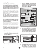
3. Loosen outfeed table lock located at front of
machine, and loosen jam nuts and stop bolts
located under outfeed table (see Figure 47).
Checking/Adjusting
Table Parallelism
Checking Outfeed Table
Checking Outfeed Table
Checking Adjusting Table Parallelism
Figure 47. Location of outfeed table stop bolts
and jam nuts.
Stop Bolts
Jam Nuts