
Use and Care Manual


Model G0857/G0858 (Mfd. Since 02/19)
-21-
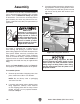
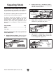
4. Tighten mobile base lock knobs (see
Figure 11) so jointer will not easily move.
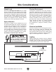
7. Connect switch cord to motor cord and install
fence tilt handle (see Figure 13).
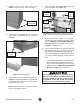
8. Verify outfeed table height is set correctly
with knives/inserts at top dead center (TDC)
(refer to Setting Outfeed Table Height on
Page 47) and all knives/inserts are securely
tightened in cutterhead.
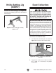
9. Verify proper operation of cutterhead guard
by moving fence to rear of table, then pull-
ing cutterhead guard back and letting it go. It
should spring back over cutterhead and con-
tact fence without dragging across outfeed
table.
— If cutterhead guard does not spring back
over cutterhead and contact fence, or it
drags across outfeed table, then it must be
adjusted (refer to Adjusting Cutterhead
Guard on Page 54 for instructions).
Figure 11. Location of mobile base locks.
Mobile Base
Lock Knobs
5. Adjust feet (see Figure 12) as necessary
until jointer is stable without any rocking or
wobbling.
Adjustable
Feet
Figure 12. Leveling jointer.
The cutterhead guard is a critical safety
feature of this jointer. You MUST verify its
operation before using the jointer! Failure
to properly install this guard will greatly
increase risk of serious personal injury.
6. Reposition and secure switch pedestal (see
Figure 13) in upright position with (2) M8-1.25
x 20 cap screws and (2) 8mm lock washers
pre-installed on stand.
Note: Switch pedestal is mounted upside-
down for shipping purposes.
Motor
Cord
Figure 13. Switch pedestal attached to stand,
cords connected, and fence tilt handle installed.
Switch
Pedestal
Switch
Cord
Fence
Tilt
Handle