MODEL G1183/G1276 HEAVY-DUTY COMBINATION SANDER OWNER'S Manual Copyright © 1989 By Grizzly Industrial, Inc., Revised APRIL, 2011 (TS) Warning: No portion of this manual may be reproduced in any shape Or form without the written approval of Grizzly Industrial, inc.
This manual provides critical safety instructions on the proper setup, operation, maintenance, and service of this machine/tool. Save this document, refer to it often, and use it to instruct other operators. Failure to read, understand and follow the instructions in this manual may result in fire or serious personal injury—including amputation, electrocution, or death. The owner of this machine/tool is solely responsible for its safe use.
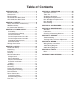
Table of Contents INTRODUCTION................................................ 2 Manual Accuracy............................................ 2 Contact Info.................................................... 2 Basic Controls................................................. 3 G1183 Machine Data Sheet........................... 4 G1276 Machine Data Sheet........................... 6 SECTION 1: SAFETY........................................ 8 Safety Instructions for Machinery...................
INTRODUCTION Manual Accuracy Contact Info We are proud to offer this manual with your new machine! We've made every effort to be exact with the instructions, specifications, drawings, and photographs of the machine we used when writing this manual. However, sometimes we still make an occasional mistake. We stand behind our machines. If you have any questions or need help, use the information below to contact us. Before contacting, please get the serial number and manufacture date of your machine.
Basic Controls Having a good understanding of the basic controls of the sander is important to properly set up the machine and successfully complete the test run. Refer to Figure 5 and the following descriptions to gain this understanding. A. Upper Roller Adjustment Screws: Control the tilt of the upper roller and are used to make it parallel with the lower roller for tracking purposes. B.
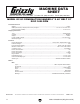
MACHINE DATA SHEET Customer Service #: (570) 546-9663 · To Order Call: (800) 523-4777 · Fax #: (800) 438-5901 MODEL G1183 COMBINATION SANDER 6" X 48" BELT 12" DISC 3450 RPM Product Dimensions: Weight.............................................................................................................................................................. 144 lbs. Width (side-to-side) x Depth (front-to-back) x Height........................................................ 32-1/2 x 16-1/2 x 29-1/2 in.
Main Specifications: Belt Sander Info Sanding Belt Width...................................................................................................................................... 6 in. Sanding Belt Length.................................................................................................................................. 48 in. Sanding Belt Speed...........................................................................................................................
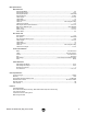
MACHINE DATA SHEET Customer Service #: (570) 546-9663 · To Order Call: (800) 523-4777 · Fax #: (800) 438-5901 MODEL G1276 COMBINATION SANDER 6" X 48" BELT 12" DISC 1725 RPM Product Dimensions: Weight.............................................................................................................................................................. 145 lbs. Width (side-to-side) x Depth (front-to-back) x Height........................................................ 32-1/2 x 16-1/2 x 29-1/2 in.
Main Specifications: Belt Sander Info Sanding Belt Width...................................................................................................................................... 6 in. Sanding Belt Length.................................................................................................................................. 48 in. Sanding Belt Speed...........................................................................................................................
SECTION 1: SAFETY For Your Own Safety, Read Instruction Manual Before Operating This Machine The purpose of safety symbols is to attract your attention to possible hazardous conditions. This manual uses a series of symbols and signal words intended to convey the level of importance of the safety messages. The progression of symbols is described below. Remember that safety messages by themselves do not eliminate danger and are not a substitute for proper accident prevention measures.
WEARING PROPER APPAREL. Do not wear clothing, apparel or jewelry that can become entangled in moving parts. Always tie back or cover long hair. Wear non-slip footwear to avoid accidentalslips,whichcouldcauselossofworkpiececontrol. hAzARdOus dusT. Dust created while using machinery may cause cancer, birth defects, or long-term respiratory damage.
Additional Safety for Combination Sanders DISC DIRECTION. Only sand on the downwardmoving left side of the sanding disc. Sanding on the upward-moving right side of the sanding disc forces the operator to rely only on hands (rather than the table) for support, which increases the risk of workpiece "kick-out" and impact/abrasion injuries. WORKPIECE INSPECTION.
SECTION 2: POWER SUPPLY Availability Circuit Information Before installing the machine, consider the availability and proximity of the required power supply circuit. If an existing circuit does not meet the requirements for this machine, a new circuit must be installed. To minimize the risk of electrocution, fire, or equipment damage, installation work and electrical wiring must be done by an electrican or qualified service personnel in accordance with all applicable codes and standards.
Grounding Requirements This machine MUST be grounded. In the event of certain malfunctions or breakdowns, grounding reduces the risk of electric shock by providing a path of least resistance for electric current. For 110V operation: This machine is equipped with a power cord that has an equipment-grounding wire and a grounding plug (see following figure).
Extension Cords We do not recommend using an extension cord with this machine. If you must use an extension cord, only use it if absolutely necessary and only on a temporary basis. Extension cords cause voltage drop, which may damage electrical components and shorten motor life. Voltage drop increases as the extension cord size gets longer and the gauge size gets smaller (higher gauge numbers indicate smaller sizes).
SECTION 3: SETUP Needed for Setup This machine presents serious injury hazards to untrained users. Read through this entire manual to become familiar with the controls and operations before starting the machine! Wear safety glasses during the entire setup process! This machine and its components are very heavy. Get lifting help or use power lifting equipment such as a forklift to move heavy items.
Inventory The following is a list of items shipped with your machine. Before beginning setup, lay these items out and inventory them. A B C If any non-proprietary parts are missing (e.g. a nut or a washer), we will gladly replace them; or for the sake of expediency, replacements can be obtained at your local hardware store. D E G Shipping Inventory: (Figure 8) Qty A. Sander Assembly........................................1 B. Sanding Belt Table......................................1 C.
Cleanup The unpainted surfaces of your machine are coated with a heavy-duty rust preventative that prevents corrosion during shipment and storage. This rust preventative works extremely well, but it will take a little time to clean. Be patient and do a thorough job cleaning your machine. The time you spend doing this now will give you a better appreciation for the proper care of your machine's unpainted surfaces.
Site Considerations Weight Load Physical Environment Refer to the Machine Data Sheet for the weight of your machine. Make sure that the surface upon which the machine is placed will bear the weight of the machine, additional equipment that may be installed on the machine, and the heaviest workpiece that will be used. Additionally, consider the weight of the operator and any dynamic loading that may occur when operating the machine.
Mounting The base of this machine has holes that accept 5 ⁄ 8" bolts for mounting the machine to a workbench. We strongly recommend that you mount your machine to a workbench to prevent it from moving during operation. An unexpected movement could result in an injury or property damage. Assembly To assemble the sander: 1. Unthread the screw cap on the sanding belt table lock lever, remove the lever, then unthread the lock bolt and flat washer from the sander (see Figure 12).
4. Attach the sanding belt table to the trunnion by finger tightening the (3) 5⁄16"-11 x 1" hex bolts and 5⁄16" flat washers from underneath the table, as shown in Figure 14. The hex bolts will be fully tightened when aligning the tables in later steps. 6. Loosen the sanding belt pivot cap screw shown in Figure 16, rotate the sanding belt assembly to the vertical position, then retighten the cap screw to hold it place. x3 Pivot Cap Screw Figure 14. Sanding belt table installed. 5.
Table Gap Adjustment 8. Loosen the sanding disc table lock knobs, then move the trunnion brackets away from the lower disc guard, as shown in Figure 18. Trunnion Bracket (1 of 2) To reduce the risk of in-running nip (pinch) points, yet avoid the risk of the sandpaper contacting the tables, the tables should be adjusted away from the sandpaper no more than 1⁄ 16". Note: The procedure for the table gap adjustment is similar for both tables. To adjust the table-to-sandpaper gap: Lock Knob Figure 18.
3. Loosen the hex bolts underneath the table that secure it to the trunnion(s). Note: The sanding belt table has three hex bolts (see Figure 21), and the sanding disc table has two hex bolts on both sides of the table (see Figure 22). Checking Belt Tracking Proper belt tracking depends on two conditions: 1) The platen height, and 2) the upper roller parallelism.
Dust Collection To connect the sander to the dust collection system: 1. DO NOT operate the Model G1183/G1276 without an adequate dust collection system. This sander creates substantial amounts of wood dust while operating. Failure to use a dust collection system can result in short and long-term respiratory illness. Recommended CFM at: 3" Dust Port................................. 220 CFM 2 1⁄ 2" Dust Hose............................
Power Connection Test Run After you have completed all previous setup instructions and circuit requirements, the machine is ready to be connected to the power supply. Once the assembly is complete, test run your machine to make sure it runs properly. To avoid unexpected startups or property damage, use the following steps whenever connecting or disconnecting the machine. Connecting Power 1. Turn the machine power switch OFF. 2. Insert the power cord plug into a matching power supply receptacle.
SECTION 4: OPERATIONS Operation Overview The purpose of this overview is to provide the novice machine operator with a basic understanding of how the machine is used during operation, so the machine controls/components discussed later in this manual are easier to understand. Due to the generic nature of this overview, it is not intended to be an instructional guide.
Table Tilt Angle sanding is performed with the table tilted away from 0° (perpendicular to the sanding surface). Compound angles are sanded using a combination of table tilt and miter gauge angle. Table Tilt Ranges Sanding Belt Table........................... -45° to +45° Sanding Disc Table.......................... -40° to +30° Both tables have an adjustable positive stop that is used to quickly return the table to 0°. The belt table has an additional stop at -45° and uses a flip stop to engage the stops.
Sandpaper Selection Sanding a workpiece smooth requires using progressively smaller grit sandpaper until the desired finish is attained. The abrasiveness of sandpaper is designated in grit size—the larger the number, the finer the abrasive and the smaller the scratches. Thus, 100 grit is finer than 60 grit. Typically, sanding operations start with a coarse grit and progressively work through the finer (larger number) grits until the desired finish is achieved.
Disc Sandpaper Replacement The Model G1183/G1276 sander ships with a preinstalled 80-grit, 12" diameter adhesive-backed sanding disc. The sanding disc sticks to the surface of the cast iron disc platen, using the pressure-sensitive adhesive (PSA) backing. The sandpaper can be replaced without removing the table or dust port. To replace the disc sandpaper: 1. DISCONNECT SANDER FROM POWER! Disc Sanding Only sand on the downward-moving left side of the sanding disc.
Belt Sanding The sanding belt removes material faster than the sanding disc, and can be secured at any angle from horizontal to completely vertical with the use of the pivot cap screw shown in Figure 36. Figure 34. Example of compound angle sanding. Figure 35. Example of round workpiece sanding. Pivot Cap Screw Figure 36. Positioning the sanding belt assembly.
Always sand with the workpiece supported by the table. Relying only hands to support the workpiece increases the risk of workpiece "kick-out" and impact/abrasion injuries. Refer to Figures 37–40 for examples of sanding operations that are possible with the belt sanding assembly. Figure 39. Example of vertical miter sanding. Figure 37. Sanding workpiece in horizontal position. Figure 40. Examples of vertical face and edge sanding.
SECTION 5: ACCESSORIES Some aftermarket accessories can be installed on this machine that could cause it to function improperly, increasing the risk of serious personal injury. To minimize this risk, only install accessories recommended for this machine by Grizzly. G2405—Safety Push Blocks Made of high-impact molded plastic, these safety push blocks have a layer of friction rubber on the bottom that grabs your workpiece as you press down.
Pro-Stik® Abrasive Belt Cleaners G1511—Small: (1 1/2" x 1 1/2" x 8 1/2") G1512—Large: (2 " x 2" x 12") H2499—Small Half-Mask Respirator H3631—Medium Half-Mask Respirator H3632—Large Half-Mask Respirator H3635—Cartridge Filter Pair P100 Wood dust has been linked to nasal cancer and severe respiratory illnesses. If you work around dust everyday, a half-mask respirator can be a lifesaver. Also compatible with safety glasses! Figure 43. Pro-Stik® Belt Cleaners.
SECTION 6: MAINTENANCE Always disconnect power to the machine before performing maintenance. Failure to do this may result in serious personal injury. Schedule For optimum performance from your machine, follow this maintenance schedule and refer to any specific instructions given in this section. Before & During Operation: • Loose mounting bolts. • Damaged, excessively worn, or clogged sandpaper. Worn or damaged switch or wires. • • Excessive dust build-up. • Efficiency of the dust collection system.
SECTION 7: SERVICE Review the troubleshooting and procedures in this section to fix or adjust your machine if a problem develops. If you need replacement parts or you are unsure of your repair skills, then feel free to call our Technical Support at (570) 546-9663. Troubleshooting Symptom Possible Cause Possible Solution Machine does not start or a breaker trips. 1. Power supply switched OFF or at fault. 2. Plug/receptacle at fault/wired wrong. 3. Motor connection wired wrong. 4.
Symptom Possible Cause Possible Solution Sanded surface not square. 1. Work table not perpendicular to belt or disc. 2. Miter gauge not square to disc. 1. Adjust work table square to sanding belt and disc (see Page 20). 2. Adjust face of the miter gauge square to disc or belt. Deep sanding grooves or scars in workpiece. 1. Sandpaper too coarse for the desired finish. 2. Workpiece sanded across the grain. 3. Too much sanding force on workpiece. 4. Workpiece held still against the belt/disc. 1.
Tracking Roller & Platen Adjustment 4. Place the straightedge over the platen and upper roller aligned with the middle of the roller (the crown at the highest point), as shown in Figure 49. To ensure proper belt tracking, the belt platen must be even with the upper roller crown and the upper and lower rollers must be parallel. To adjust the roller and platen: 1. DISCONNECT SANDER FROM POWER! 1. Remove the side cover and table from the belt assembly. 2.
6. Fully loosen the locking thumb wheels on both of the roller adjustment screws shown in Figure 50. 8. Make small changes to the adjustment knobs as you continue to rotate the sanding belt by hand. 9. Adjustment Screws & Locking Thumb Wheels When the sanding belt continues to track in one position on the rollers, make sure both adjustment screws are making contact with the belt housing, then re-tighten the locking thumb screws. 10.
SECTION 8: WIRING These pages are current at the time of printing. However, in the spirit of improvement, we may make changes to the electrical systems of future machines. Study this section carefully. If there are differences between your machine and what is shown in this section, call Technical Support at (570) 546-9663 for assistance BEFORE making any changes to the wiring on your machine. Wiring Safety Instructions SHOCK HAZARD.
110V Wiring Diagram Figure 51. Switch and motor wiring. A1 A2 A3 A1 A2 A3 B1 B2 B3 ON/OFF Switch B1 B2 B3 Motor (viewed from bottom) Ground Run Capactitor 25M 350V Start Capactitor 200M 250V Hot Ground -38- READ ELECTRICAL SAFETY ON PAGE 37! Neutral 110VAC NEMA 5-15 (As Recommended) Model G1183/G1276 (Mfg.
220V Wiring Diagram A1 A2 A3 A1 A2 A3 B1 B2 B3 ON/OFF Switch B1 B2 B3 Motor (viewed from bottom) Ground Run Capactitor 25M 350V Start Capactitor 200M 250V Hot Ground G Hot Model G1183/G1276 (Mfg.
-40- 24 9 1 127 4 21 7V2-1 18 19 16 17 11 20 107 126 118 22 137 8 27 111 105 25 2 113 3 133 69 4 5 132 6 7V2-2 13 12 23 28 29 26 15 10 131 14 42 41-1 38 37 96 31 123 47 130 32 40 33 35 129 39 24 25 34 55 109 44 128 43 46 45 48 49 106 104 94 128 65 70 95 57 64 67 43 42 100 99 102 51 50 103 120 129 41 40 121 135 122 119 124 125 68 72 66 73 77 110 100 108 101 136 54 59 66 71 78 58 56 76 74 80 81 75 79 56 115 134 93 92 91
Main Parts List REF PART # DESCRIPTION REF PART # DESCRIPTION 1 2 3 4 5 6 7V2-1 7V2-2 8 9 10 11 12 13 14 15 16 17 18 18 19 19 20 21 22 23 24 25 26 27 28 28 29 29 30 31 32 33 34 35 36V2 37 38 39 40 41 41-1 BASE ALUMINUM BASE PLATE PLASTIC HEX BOLT M8-1.25 X 12 FLANGE SCREW 10-24 X 3/8 EXT TOOTH WASHER #10 CAPACITOR CLIP S CAPACITOR 200M 250V 1-1/2 X 3-1/8 R CAPACITOR 25M 350V 1-1/2 X 3-5/8 PUSH BUTTON SWITCH 110/220V PHLP HD SCR 10-24 X 1-1/4 MOTOR BASE CAP SCREW M8-1.
Main Parts List REF PART # DESCRIPTION REF PART # DESCRIPTION 89 90 91 92 93 94 95 96 97 98 99 100 101 102 103 104 105 106 107 107 108 109 110 111 COMPRESSION SPRING LOCK HANDLE SCREW ALUMINUM POINTER FLAT WASHER #10 PHLP HD SCR 10-24 X 1/4 DEGREE SCALE STEEL FLUTED RIVET 2 X 5MM BELT SANDER TABLE FLAT WASHER 5/16 HEX BOLT 5/16-18 X 1 DISC SANDER TABLE TABLE TRUNNION DEGREE SCALE HEX BOLT 5/16-18 X 3/4 FLAT WASHER 5/16 BELT GUARD MOTOR FAN PLASTIC FLANGE SCREW 1/4-20 X 1/2 ROTOR 2-POLE 80 X 50MM (G1183
WARRANTY CARD Name _____________________________________________________________________________ Street _____________________________________________________________________________ City _______________________ State _________________________ Zip _____________________ Phone # ____________________ Email _________________________________________________ Model # ____________________ Order # _______________________ Serial # __________________ The following information is given on a voluntary basis.
FOLD ALONG DOTTED LINE Place Stamp Here GRIZZLY INDUSTRIAL, INC. P.O.
WARRANTY AND RETURNS WARRANTY AND RETURNS Grizzly Industrial, Inc. warrants every product it sells for a period of 1 year to the original purchaser from the date of purchase. This warranty does not apply to defects due directly or indirectly to misuse, abuse, negligence, accidents, repairs or alterations or lack of maintenance.