MODEL G4181/G7873 1-HP POWER FEEDER OWNER'S MANUAL (For models manufactured since 12/13) COPYRIGHT © JULY, 2008 BY GRIZZLY INDUSTRIAL, INC. REVISED APRIL, 2014 (TS) WARNING: NO PORTION OF THIS MANUAL MAY BE REPRODUCED IN ANY SHAPE OR FORM WITHOUT THE WRITTEN APPROVAL OF GRIZZLY INDUSTRIAL, INC. #CR10817 PRINTED IN TAIWAN V2.04.
This manual provides critical safety instructions on the proper setup, operation, maintenance, and service of this machine/tool. Save this document, refer to it often, and use it to instruct other operators. Failure to read, understand and follow the instructions in this manual may result in fire or serious personal injury—including amputation, electrocution, or death. The owner of this machine/tool is solely responsible for its safe use.
Table of Contents INTRODUCTION................................................ 2 Manual Accuracy............................................ 2 Contact Info.................................................... 2 Machine Data Sheet (G4181)......................... 3 Machine Data Sheet (G7873)......................... 5 Components & Terminology........................... 7 SECTION 1: SAFETY........................................ 8 Safety Instructions for Machinery...................
INTRODUCTION Manual Accuracy Contact Info We are proud to provide a high-quality owner’s manual with your new machine! We stand behind our machines! If you have questions or need help, contact us with the information below. Before contacting, make sure you get the serial number and manufacture date from the machine ID label. This will help us help you faster. We made every effort to be exact with the instructions, specifications, drawings, and photographs in this manual.
Machine Data Sheet (G4181) MACHINE DATA SHEET Customer Service #: (570) 546-9663 · To Order Call: (800) 523-4777 · Fax #: (800) 438-5901 MODEL G4181 1 HP POWER FEEDER Product Dimensions: Weight.............................................................................................................................................................. 130 lbs. Width (side-to-side) x Depth (front-to-back) x Height........................................................................... 44 x 16 x 30 in.
Operation Info Number of Feed Speeds.................................................................................................................................. 4 Feed Speeds........................................................................................................................ 13, 26, 33, 66 FPM Swing.................................................................................................................................................... 360 deg. Vertical Movement............
Machine Data Sheet (G7873) MACHINE DATA SHEET Customer Service #: (570) 546-9663 · To Order Call: (800) 523-4777 · Fax #: (800) 438-5901 MODEL G7873 1 HP 3‐PHASE POWER FEEDER Product Dimensions: Weight.............................................................................................................................................................. 135 lbs. Width (side-to-side) x Depth (front-to-back) x Height.................................................................
Operation Info Number of Feed Speeds.................................................................................................................................. 4 Feed Speeds........................................................................................................................ 13, 26, 33, 66 FPM Swing.................................................................................................................................................... 360 deg. Vertical Movement............
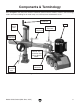
Components & Terminology Refer to Figure 1 and your power feeder to familiarize yourself with the controls, features, and terminology used in this manual. Doing so will make setup, use, and any future maintenance easier. Vertical Travel Handcrank Motor Vertical Travel Lock Horizontal Travel Lock Upper Elbow Joint Lock Horizontal Handwheel Gearbox Oil Plug Labeled "OIL" Located on Top of Case Behind Motor Lower Elbow Joint Lock Rotary Movement Lock Figure 1. Controls and features.
SECTION 1: SAFETY For Your Own Safety, Read Instruction Manual Before Operating This Machine The purpose of safety symbols is to attract your attention to possible hazardous conditions. This manual uses a series of symbols and signal words intended to convey the level of importance of the safety messages. The progression of symbols is described below. Remember that safety messages by themselves do not eliminate danger and are not a substitute for proper accident prevention measures.
WEARING PROPER APPAREL. Do not wear clothing, apparel or jewelry that can become entangled in moving parts. Always tie back or cover long hair. Wear non-slip footwear to reduce risk of slipping and losing control or accidentally contacting cutting tool or moving parts. HAZARDOUS DUST. Dust created by machinery operations may cause cancer, birth defects, or long-term respiratory damage. Be aware of dust hazards associated with each workpiece material.
Additional Safety for Power Feeders Serious injury or death can occur from getting hands, clothing, or jewelry entangled in moving parts of power feeder or being pulled into cutting tool on attached machinery. Workpieces ejected by attached machine can strike operator or bystanders with significant force, causing impact injuries. To minimize risk of injury, anyone operating this machine MUST completely heed hazards and warnings below. ATTACHED MACHINERY.
SECTION 2: POWER SUPPLY Availability G4181 Circuit Requirements Before installing the machine, consider the availability and proximity of the required power supply circuit. If an existing circuit does not meet the requirements for this machine, a new circuit must be installed. To minimize the risk of electrocution, fire, or equipment damage, installation work and electrical wiring must be done by an electrician or qualified service personnel in accordance with all applicable codes and standards.
Grounding Instructions This machine MUST be grounded. In the event of certain malfunctions or breakdowns, grounding reduces the risk of electric shock by providing a path of least resistance for electric current. The plug specified under "Circuit Requirements" on the previous page has a grounding prong that must be attached to the equipment-grounding wire on the included power cord.
SECTION 3: SETUP Unpacking Needed for Setup This machine was carefully packaged for safe transport. When unpacking, separate all enclosed items from packaging materials and inspect them for shipping damage. If items are damaged, please call us immediately at (570) 546-9663. The following are needed to complete the setup process, but are not included with your machine.
Inventory A The following is a list of items shipped with your machine. Before beginning setup, lay these items out and inventory them. B If any non-proprietary parts are missing (e.g. a nut or a washer), we will gladly replace them; or for the sake of expediency, replacements can be obtained at your local hardware store. Box Inventory (Figures 4 & 5) Qty A. Power Feeder Assembly............................. 1 B. Lubricator.................................................... 1 C.
Cleanup The unpainted surfaces of your machine are coated with a heavy-duty rust preventative that prevents corrosion during shipment and storage. This rust preventative works extremely well, but it will take a little time to clean. Be patient and do a thorough job cleaning your machine. The time you spend doing this now will give you a better appreciation for the proper care of your machine's unpainted surfaces.
Assembly To correctly position this power feeder on your table top, completely assemble the power feeder first in the order of A, B and C as shown in Figures 7 and 8. Next, refer to Base Mounting on Page 15. With the power feeder unit completely assembled, it will be easier to locate where on the table top you will need to drill your base mounting holes, so you can take advantage of the full range of power feeder swing and adjustments. C Figure 8. Assembled unit.
Base Mounting Position the power feeder on the table top to determine where to drill your base mounting holes, so you can maximize power feeder swing and adjustment options. There are two mounting options available: Through Bolt Mounting and Direct Mounting (discussed on Page 18). Choose an option that suits your requirements. Also, you must be able to point the power feeder slightly towards the machine fence (see Figure 9).
Mounting Options To correctly position this power feeder on your table top, completely assemble the power feeder first, then refer to this section and mount your base to the table using one of the two methods below. The reason for this order is that with the power feeder unit completely assembled, it will be easier to locate where on the table top you will need to drill your base mounting holes, so you can take advantage of the full range of power feeder swing and adjustments.
Test Run Once the power feeder assembly is complete and mounted on the table, you must test run your power feeder to make sure it runs properly. If, during the test run, you cannot easily locate the source of an unusual noise or vibration, stop using the power feeder immediately, then review the Troubleshooting table on Page 24. If you still cannot remedy a problem, contact our Technical Support at (570) 546-9663 for assistance. 6.
SECTION 4: OPERATIONS Basic Use and Care To reduce your risk of serious injury, read this entire manual BEFORE using machine. To reduce risk of eye injury from flying chips or lung damage from breathing dust, always wear safety glasses and a respirator when operating this machine. Loose hair, clothing, or jewelry could get caught in machinery and cause serious personal injury. Keep these items away from moving parts at all times to reduce this risk.
Changing Feed Speed 4. Remove the chain cover and the two hex nuts securing the position A & B change gears to the shafts. 5. Swap the required change gears so the gear hubs are facing toward the power feeder (shown in positions A & B in Figure 13). Your power feeder has the option to feed a workpiece at 13, 26, 33, and 66 feet per minute.
SECTION 5: MAINTENANCE • After the first 200 hours of use, or after the first month, change the gearbox oil with 5.1 fluid ounces of a good automotive grade 80-90W gear oil. For the remaining life of the power feeder, change the oil every 1000 hours, or every 6 months. Note: To drain the unit, remove the fill plug labeled "OIL" and invert the power feeder.
ACCESSORIES SECTION 6: ACCESSORIES Installing unapproved accessories may cause machine to malfunction, resulting in serious personal injury or machine damage. To reduce this risk, only install accessories recommended for this machine by Grizzly. G3101—Polyurethane Roller G2516—Rubber Roller Polyurethane or rubber rollers fits the G3100 or G1759 roller flange tire system. NOTICE Refer to our website or latest catalog for additional recommended accessories.
SECTION 7: SERVICE Review the troubleshooting and procedures in this section if a problem develops with your machine. If you need replacement parts or additional help with a procedure, call our Technical Support. Note: Please gather the serial number and manufacture date of your machine before calling. Troubleshooting Motor & Electrical Symptom Possible Cause Motor will not start. 1. Check power supply for proper voltage. 1. Low voltage. 2. Open circuit in motor or loose connections. 2.
Wheel Replacement 2. Using a 5mm hex wrench, remove the two wheel retaining cap screws (see Figure 21). Always disconnect power to the machine before performing maintenance. Failure to do this may result in serious personal injury. Cap Screw If you damage one or more wheels, you can easily replace the wheels. Figure 21. Wheel replacement. Tools Needed Qty Hex Wrench 5mm........................................ 1 • 3. Swap the old wheel with the new. To replace a wheel: 4.
G4181 Wiring Diagram View this page in color at www.grizzly.com. 220V Two Speed Motor 4 Side B 2 R 1 7 8 6 S 5 U 11 12 10 W 9 Y 15 16 14 X 13 19 20 23 V 24 Z 18 22 1 4 17 T 21 35MFD 400VAC 3 Two Speed Motor Direction Switch Capacitor Side A Ground 6 3 5 2 Hot G Hot 6-15 Plug (As Recommended) Figure 22. Motor power and direction switch. -26- Figure 23. Motor switch and capacitor. Model G4181/G7873 (Mfd.
G7873 Wiring Diagram View this page in color at www.grizzly.com. 220V Two Speed Motor Side A 3 4 Two Speed Motor Direction Switch Side B 2 R 1 7 8 6 S 5 U 11 12 10 W 9 Y 15 16 14 X 13 19 20 Z 18 3 4 17 Ground 6 1 V 24 22 T 21 5 2 Ground Hot Hot Hot 23 G X Z W 220V VAC 3-Phase 15-15 Plug (As Recommended) Figure 24. Motor switch (side view). Model G4181/G7873 (Mfd. Since 12/13) Figure 25. Motor switch (front view).
-28- 591 592 529 531 518 528 503 515 553 514 517 516 502 576 531-1 529 510 578 528 536 531-2 501 509 594 563 505 511 571 506 554 570 508 526 509 550 522 530 509 588 512 586 595 596 556 565 567 511 506 508 568 505 570 571 554 558 504 552 505 566 557 555 511 507 568 508 571 552 554 504 570 504 558 557 557 558 562 545-4 566 555 556 561556 25 555 521-1 521 590 589 565 567 521-2 547 546 545 (G4181 Single-Phase) 599 (G7873 Three-Phase) 593 560 559 545-3 526
Main Parts List REF PART # DESCRIPTION REF PART # DESCRIPTION 501 502 503 504 505 506 507 508 509 510 511 512 514 515 516 517 518 521 521-1 521-2 522 522-1 526 528 529 530 531 531-1 531-2 531-3 536 538 545 545-1 545-2 545-3 P4181501 P4181502 P4181503 P4181504 P4181505 P4181506 P4181507 P4181508 P4181509 P4181510 P4181511 P4181512 P4181514 P4181515 P4181516 P4181517 P4181518 P4181521 P4181521-1 P4181521-2 P4181522 P4181522-1 P4181526 P4181528 P4181529 P4181530 P4181531 P4181531-1 P4181531-2 P4181531-3
Base Breakdown 687 686A 686 685A 681-3 635 685 678-4 681-6 681-5 681-7 678-2V2 629 684 678-3 678-5 681V2 681-4 676-1V2 681-2V2 681-1 678-3 678-4 649A 649 651 678-1 623V2 678-5 698-5 698-2V2 699-4 636V2 635 678-2V2 699-2 698-3 698-4 699 699-1 680 698-1 698A 650 634 698-7 698-6 602 601 603 636A 680A REF PART # DESCRIPTION REF PART # DESCRIPTION 601 602 603 623V2 629 634 635 636A 636V2 649A 649 650 651 676-1V2 678-1 678-2V2 678-3 678-4 678-5 680A 680 681V2 681-1 681-2
WARRANTY CARD Name _____________________________________________________________________________ Street _____________________________________________________________________________ City _______________________ State _________________________ Zip _____________________ Phone # ____________________ Email _________________________________________________ Model # ____________________ Order # _______________________ Serial # __________________ The following information is given on a voluntary basis.
FOLD ALONG DOTTED LINE Place Stamp Here GRIZZLY INDUSTRIAL, INC. P.O.
WARRANTY & RETURNS Grizzly Industrial, Inc. warrants every product it sells for a period of 1 year to the original purchaser from the date of purchase. This warranty does not apply to defects due directly or indirectly to misuse, abuse, negligence, accidents, repairs or alterations or lack of maintenance.