
Use and Care Manual

-20-
Model G5912Z/G7214Z (Mfd. Since 01/17)
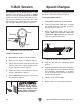
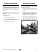
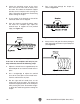
Figure 22. Example of hold-downs on workpiece.
Figure 23. Overview of hold-downs in place.
2. Insert the bracket pole into the fence bracket
and hold-down bracket.
3. Partially screw handle into hold-down brackets.
4. Slide two hold-down brackets into miter slot.
Position so they are across from fence mount-
ed hold-downs (see Figure 23). Tighten with
the knob on top of each miter hold-down.
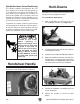
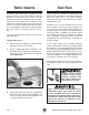
Figure 21. Handwheel mounted to shaper.
Handwheel Handle
Thread the crank handle onto the handwheel.
Hold-Downs
Hold-downs are used to hold the workpiece flat on
the table and snug against the fence.
To assemble the hold-downs:
1. Slide a hold-down bar into each of the cast
iron hold-down brackets (see Figure 22).
5. Position the hold-downs according to the size
of your workpiece.
6. Tighten the handles to secure the hold-
downs.
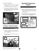
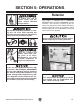
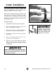
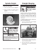
Spindle Enclosure Guard Positioning
The spindle enclosure guard protects the user
from exposure to the cutter and chips thrown by
it. To minimize the risk of injury, the spindle enclo-
sure guard must be adjusted so it encloses as
much of the spindle area as possible, while still
allowing the workpiece to pass through the cut.
Typically this means the front guard is positioned
to just clear the top of the workpiece.
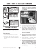
To position the spindle enclosure guard, loosen
the top knob bolts and slide the extension plate in
or out, then loosen the front knob bolts and raise
or lower the spindle enclosure guard as needed.
Tighten the knob bolts to secure the setting.
All guards MUST be
installed on your shaper
before operating it.
Shapers can quickly cause
serious injury if some kind
of guard is not used. To
reduce your risk of injury,
read and follow the entire
Owner's Manual carefully
and do additional research
on shop made guards and
safety jigs.