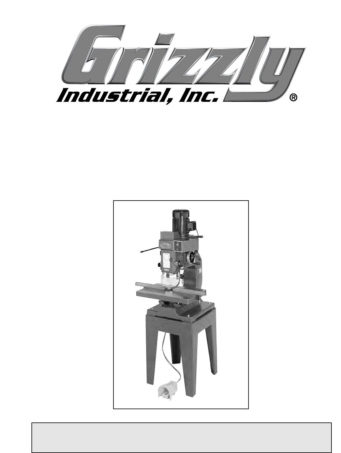
3 H.P. OVERARM ROUTER MODEL G8030 INSTRUCTION MANUAL COPYRIGHT © 2001 BY GRIZZLY INDUSTRIAL, INC. WARNING: NO PORTION OF THIS MANUAL MAY BE REPRODUCED IN ANY SHAPE OR FORM WITHOUT THE WRITTEN APPROVAL OF GRIZZLY INDUSTRIAL, INC.
Table Of Contents 1. 2. 3. 4. 5. 6. 7. 8. PAGE SAFETY SAFETY RULES FOR ALL TOOLS..................................................................2-3 ADDITIONAL SAFETY INSTRUCTIONS FOR OVERARM ROUTERS ..............4 CIRCUIT REQUIREMENTS ........................................................................................ 220V OPERATION ..............................................................................................5 CIRCUIT LOAD .....................................................
SECTION 1: SAFETY For Your Own Safety Read Instruction Manual Before Operating This Equipment The purpose of safety symbols is to attract your attention to possible hazardous conditions. This manual uses a series of symbols and signal words which are intended to convey the level of importance of the safety messages. The progression of symbols is described below. Remember that safety messages by themselves do not eliminate danger and are not a substitute for proper accident prevention measures.
Safety Instructions For Power Tools 9. USE PROPER EXTENSION CORD. Make sure your extension cord is in good condition. Conductor size should be in accordance with the chart below. The amperage rating should be listed on the motor or tool nameplate. An undersized cord will cause a drop in line voltage resulting in loss of power and overheating. Your extension cord must also contain a ground wire and plug pin. Always repair or replace extension cords if they become damaged.
Additional Safety Instructions For The Overarm Router 1. ALWAYS USE A GUIDE PIN WHEN ROUTING WITHOUT THE FENCE. 2. DO NOT ROUT STOCK TOO SMALL TO HOLD SECURELY WITHOUT SPECIAL JIGS. Use longer stock and cut to size. 3. ALWAYS TEST ANY NEW TEMPLATE OR SETUP with the machine unplugged, to ensure proper template contact and swing before starting the machine. 4. NEVER ATTEMPT TO REMOVE TOO MUCH MATERIAL IN ONE PASS. Several light passes are safer and give a cleaner finish. 5.
SECTION 2: CIRCUIT REQUIREMENTS 220V Operation Circuit Load The Model G8030 has a 3 H.P., 3450 R.P.M. motor which requires a 220V single-phase circuit. The cord set enclosed does not have a plug as the style of plug you require will depend upon the type of service you currently have or plan to install. The motor will safely draw about 15 amps at 220V under load. If you operate the Model G8030 on any circuit that is already close to its capacity, it might blow a fuse or trip a circuit breaker.
Grounding In the event of a malfunction or breakdown, grounding provides electric current a path of least resistance. This tool is equipped with an electric cord having an equipment-grounding conductor which must be properly connected to a grounding plug. The plug must be plugged into a matching outlet that is properly installed and grounded in accordance with all local codes and ordinances. Improper connections of the electrical-grounding conductor can result in risk of electric shock.
SECTION 3: INTRODUCTION Commentary We are proud to offer the Grizzly Model G8030 Overarm Router. The Model G8030 is part of a growing Grizzly family of fine woodworking machinery. When used according to the guidelines set forth in this manual, you can expect years of trouble-free, enjoyable operation and proof of Grizzly’s commitment to customer satisfaction. The Model G8030 is intended for heavy-duty professional use. It features a 3 H.P.
Unpacking Piece Inventory The Model G8030 is shipped from the manufacturer in a carefully packed carton. If you discover the machine is damaged after you’ve signed for delivery, immediately call Customer Service for advice. After all the parts have been removed from the carton, you should have: When you are completely satisfied with the condition of your shipment, you should inventory its parts. The G8030 is a heavy machine, 683 lbs. shipping weight.
Clean Up The unpainted surfaces are coated with a waxy oil to protect them from corrosion during shipment. Remove this protective coating with a solvent cleaner or citrus-based degreaser such as Grizzly’s G7895 Degreaser. Avoid chlorine-based solvents as they may damage painted surfaces should they come in contact. Always follow the usage instructions on the product you choose for clean up. Do not use gasoline or other petroleum-based solvents.
SECTION 4: ASSEMBLY Beginning Assembly All die-cut metal parts have a sharp edge (called “flashing”) on them after they are formed. This is removed at the factory. Sometimes, though, a bit of flashing might escape inspection. Please examine the edges of all die-cut metal parts before handling them or serious injury may occur. ! Power Panel The power panel at the rear of the Model G8030 must be properly wired with a safe ground.
Spindle Rotation Check Air Tubes/Foot Switch Connection The Model G8030 spindle must rotate in the direction of the arrow on the face of the machine. To check rotation: 1. Disconnect the machine from the power source. 2. Turn the spindle by hand as shown in Figure 3. 3. Make sure the nut is secure. 4. Start the machine and observe the direction of the spindle travel. 5. If the spindle rotates in the opposite direction, call our customer service department for help.
4. Connect an air compressor to the regulator. Air pressure must be 90 pounds per square inch. Chip Blower 5. To raise the air pressure, lift the air unit cap and turn it counterclockwise as shown in Figure 5. The air line control is used to check and control air flow to the chip blower. Cap 1. Turn control on and off to see if pressure exists as shown in Figure 6. 2. Adjust flow to most effectively remove chips from the line of sight. Lube Valve Figure 5. Lift and turn cap to adjust air pressure.
Bit Installation 3. Slide the base of the router bit into the collet as shown in Figure 8. 4. Finger tighten the nut, keeping a grip on the bit. Router bits are very sharp. Use care in handling to prevent injury. Always use bits that are rated for 20,000 R.P.M. or higher. Do not use bits that are designed for slow R.P.M. operation. If you do not know the maximum rated R.P.M. for a particular bit, do not use it in the overarm router.
Bit Tightening Installing the Shield The installed router bit must be carefully tightened. Two open end wrenches are supplied with the machine. The dust shield also serves to help keep chips away from the operator’s face. Installation is quick. 1. Place one wrench on the flats of the spindle as shown in Figure 9. 1. Slide the shield onto its post and place the post in its guide hole on the side of the head. 2. Place the second wrench on the collet nut. 2.
Installing the Brake Handle Installing the Fence The fence is used for straight routing and is easily installed and removed. The hand brake serves to stop the spindle when repositioning the workpiece. The machine must be turned off before you begin applying the brake to the spindle 1. Slide the brake lever into its hole as shown in Figure 11. 2. Tighten the hex head nut to hold the brake lever in place. 1. Place the fence at the location in which it is to be used as shown in Figure 11. 2.
SECTION 5: ADJUSTMENTS Adjusting the Belt 1. Loosen the bolts around the motor base as shown in Figure 13. All die-cut metal parts have a sharp edge (called “flashing”) on them after they are formed. This is removed at the factory. Sometimes, though, a bit of flashing might escape inspection. Please examine the edges of all die-cut metal parts before handling them. Serious injury may occur. ! Disconnect power to the machine when performing any maintenance, assembly or adjustments.
Spindle Lowering Speed Table Tilt Adjustment The Model G8030 Overarm Router uses an air valve to control the speed with which the spindle is lowered. The table on the Model G8030 adjusts from a 0° to 45° angle of tilt. The right side trunnion is marked in degrees, and both trunnions have locking handles to secure the table in the exact position needed. 1. Increase or decrease lowering speed, as desired, by turning the knurled knob as shown in Figure 13. 1.
Spindle Base Adjustment 4. Use the locking handle on the other side of the head to lock in the spindle height adjustments as shown in Figure 18. The handwheel adjusts the main spindle base up or down, as needed. 1. Unlock the spindle locking handle shown in Figure 18. 2. Turn the handwheel to decrease or increase the spindle base height from the table as shown in Figure 17. Figure 18. Locking handle. 5. Position the spindle base on the highest setting allowable.
Cutting Depth Control Knob 3. Back off the locking nut a quarter turn. Then adjust the bolt as shown in Figure 20. The Model G8030 uses a rapid adjusting ring to control the cutting depth of the spindle. There are six settings on the ring. 1. Simply twist the ring to the adjustment that corresponds with the depth required as shown in Figure 19. Figure 20. Locking bolts and lock nuts. 4. Retighten locking nuts and check settings. 5. Bolt heads can be reached in sequence by turning the depth control ring.
SECTION 6: OPERATIONS Test Run ! Disconnect power to the machine when performing any maintenance, assembly or adjustments. Failure to do this may result in serious personal injury. Keep loose clothing rolled up and out of the way of machinery and keep hair pulled back. Wear safety glasses during the entire operation process. Failure to comply may result in serious personal injury. Always use bits that are rated for 20,000 R.P.M. or higher. Do not use bits that are designed for slow R.P.M. operation.
The key to successful pattern routing is having good patterns to follow. The time you spend making accurate patterns will save a lot of time during production runs, as well as reducing the amount of wasted lumber from mis-cuts. Take the time to follow our pattern making directions and you will be on your way to very efficient routing operations. For this example, we will be making a “smiley” face. X Figure 22. Location of guide pin height lock.
4. Once all the waste areas have been removed from the pattern, mount them to a piece of medium density fiberboard (MDF). Center and glue the pattern pieces to the MDF. 5. Cut (4) 1⁄2" wide strips of the same birch plywood used for the pattern. Glue them on the four sides of the MDF, on the same side as the pattern. These will serve as runners to keep the whole assembly level when performing the routing operation as shown in Figure 24. Figure 25. Top side of the pattern template.
Straight Routing Dust Control The overarm router can also be used to do straight routing procedures as well. The overarm router comes with a clamp-on fence that can be adjusted on the table. The guide pin is removed when using the fence. This type of routing is the same as routing on a traditional routing table except that the router is mounted above the workpiece. The advantage of this is having increased visibility of the cut while it is being performed.
SECTION 7: MAINTENANCE General 1. Loose mounting bolts. 2. Worn switch. ! 3. Worn or damaged cords and plugs. Disconnect power to the machine when performing any maintenance, assembly or adjustments. Failure to do this may result in serious personal injury. 4. Damaged belt. 5. Inspect air fittings and hoses. 6. Any other condition that could hamper the safe operation of this machine. 7. Bleed the water out of the condenser bottle below the air regulator—everyday.
Lubrication Drive Belt The only parts on this machine that require periodic lubrication are the spindle bearings. The frequency of lubrication depends on the amount you use the overarm router. As a habit, inspect the machine at least once a month. To lubricate the spindle cartridge: Inspect regularly for tension and wear. Check pulleys to ensure that they are properly aligned. See Pulley/Drive belt sections for proper tension and pulley alignment procedures. 1.
SECTION 8: CLOSURE The following pages contain general machine data, parts diagrams/lists, a troubleshooting guide and Warranty/Return information for your Model G8030. If you need parts or help in assembling your machine, or if you need operational information, we encourage you to call our Service Department. Our trained service technicians will be glad to help you.
MACHINE DATA SHEET Customer Service #: (570) 546-9663 • To Order Call: (800) 523-4777 • Fax #: (800) 438-5901 MODEL G8030 OVERARM HIGH SPEED ROUTER Design Type...................................................................................................... Floor Model Overall Dimensions: Table ..............................................................................................................24" x 18" Overall Height ............................................................................
149 -28- G8030 3 H.P.
Ref# Part# Description Ref# Part# Description 1 P8030001 MOTOR 49 PB08M HEX BOLT M6-1.0 X 20 1-1 P8030001-1 MOTOR FAN 50 PLW03M LOCK WASHER 6MM 1-2 P8030001-2 MOTOR FAN COVER 51 P8030051 KNOB 1-3 P8030001-3 CAPACITOR COVER 52 P8030052 KNOB 1-4 PC400A S CAPACITOR 400MDF 125V 53 P8030053 POLE 2 PB01M HEX HD BOLT M10-1.
Ref# Part# Description Ref# Part# Description 101 P8030101 SPRING 127 P8030127 TABLE INSERT 102 P8030102 SPCL SETSCREW M12-1.75 X 25 128 P8030128 C-RING 103 P8030103 FRAME BODY 129 PN09M HEX NUT M12-1.75 104 P8030104 SCREW 130 PB35M HEX BOLT M12-1.75 X 40 105 P8030105 SUPPORTER 131 P8030131 FRAME FOOT 106 PS26M PHLP HD SCR M6-1.
NOTES G8030 3 H.P.
WARRANTY AND RETURNS Grizzly Industrial, Inc. warrants every product it sells for a period of 1 year to the original purchaser from the date of purchase. This warranty does not apply to defects due directly or indirectly to misuse, abuse, negligence, accidents, repairs or alterations or lack of maintenance.
WARRANTY CARD Name ____________________________________________________________________________________ Street ____________________________________________________________________________________ City ______________________________________________________________State________Zip_________ Phone Number_______________________E-Mail_______________________FAX________________________ MODEL #_G8030 3H.P.
FOLD ALONG DOTTED LINE Place Stamp Here GRIZZLY INDUSTRIAL, INC. P.O.