MODEL G9969 RADIAL DRILL PRESS OWNER'S MANUAL COPYRIGHT © MAY, 2006 BY GRIZZLY INDUSTRIAL, INC., REVISED FEBRUARY, 2014 (ST) WARNING: NO PORTION OF THIS MANUAL MAY BE REPRODUCED IN ANY SHAPE OR FORM WITHOUT THE WRITTEN APPROVAL OF GRIZZLY INDUSTRIAL, INC.
This manual provides critical safety instructions on the proper setup, operation, maintenance, and service of this machine/tool. Save this document, refer to it often, and use it to instruct other operators. Failure to read, understand and follow the instructions in this manual may result in fire or serious personal injury—including amputation, electrocution, or death. The owner of this machine/tool is solely responsible for its safe use.
Table of Contents INTRODUCTION................................................................................................................................ 4 Foreword..................................................................................................................................... 4 Contact Info................................................................................................................................. 4 Identification................................................
INTRODUCTION Foreword Contact Info We are proud to offer the Model G9969 Radial Drill Press. This machine is part of a growing Grizzly family of fine woodworking and metalworking machinery. When used according to the guidelines set forth in this manual, you can expect years of trouble-free, enjoyable operation and proof of Grizzly’s commitment to customer satisfaction.
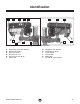
Identification A B C F G D E H J E K G I L Figure 1. G9969 Identification. A. B. C. D. E. F. Main Power and Light Switches Downfeed Handles Belt Cover Knob Belt Tension Lever Belt Tension Lock Knob Pinion Hub G9969 Radial Drill Press G. H. I. J. K. L.
Machine Data Sheet MACHINE DATA SHEET Customer Service #: (570) 546-9663 · To Order Call: (800) 523-4777 · Fax #: (800) 438-5901 MODEL G9969 RADIAL DRILL PRESS Product Dimensions: Weight.............................................................................................................................................................. 375 lbs. Width (side-to-side) x Depth (front-to-back) x Height..................................................................... 22 x 39-1/2 x 51 in.
Main Specifications: Operation Information Type......................................................................................................................................................... Radial Swing......................................................................................................................................................... 45 in. Spindle Taper.............................................................................................................................
SECTION 1: SAFETY SECTION 1: SAFETY For Your Own Safety, Read Instruction Manual Before Operating this Machine The purpose of safety symbols is to attract your attention to possible hazardous conditions. This manual uses a series of symbols and signal words intended to convey the level of importance of the safety messages. The progression of symbols is described below. Remember that safety messages by themselves do not eliminate danger and are not a substitute for proper accident prevention measures.
Safety Instructions for Machinery DISCONNECTING POWER SUPPLY. Always disconnect machine from power supply before servicing, adjusting, or changing cutting tools (bits, blades, cutters, etc.). Make sure switch is in OFF position before reconnecting to avoid an unexpected or unintentional start. INTENDED USE. Only use the machine for its intended purpose and only use recommended accessories. Never stand on machine, modify it for an alternative use, or outfit it with nonapproved accessories. STABLE MACHINE.
Safety for Drill Presses 1. EYE/FACE/HAND PROTECTION. A face shield or safety glasses is recommended. Always keep hands and fingers away from the drill bit. Never hold a workpiece by hand while drilling! DO NOT wear gloves when operating the drill. 2. SECURING BIT. Properly tighten and securely lock the drill bit in the chuck. 3. CORRECT BIT. Use only round, hex, or triangular shank drill bits. 4. ADJUSTING KEYS AND WRENCHES. Remove all adjusting keys and wrenches before turning the machine ON. 5.
SECTION 2: CIRCUIT REQUIREMENTS 110/220V Operation Serious personal injury could occur if you connect the machine to the power source before you have completed the set up process. DO NOT connect the machine to the power source until instructed to do so. Circuit Requirements We recommend using a dedicated circuit for this machine. You MUST connect your machine to a grounded circuit that is rated for the amperage given below.
Grounding In the event of an electrical short, grounding reduces the risk of electric shock. The grounding wire in the power cord must be properly connected to the grounding prong on the plug; likewise, the outlet must be properly installed and grounded. All electrical connections must be made in accordance with local codes and ordinances. Electrocution or fire could result if this machine is not grounded correctly or if your electrical configuration does not comply with local and state codes.
SECTION 3: SET UP Set Up Safety This machine presents serious injury hazards to untrained users. Read through this entire manual to become familiar with the controls and operations before starting the machine! Wear safety glasses during the entire set up process! The Model G9969 is a heavy machine. DO NOT over-exert yourself while unpacking or moving your machine—get assistance.
Inventory NOTICE After all the parts have been removed from the crate, you should have the following items: Some hardware/fasteners on the inventory list may arrive pre-installed on the machine. Check these locations before assuming that any inventory items are missing. Box 1: (Figure 3) Qty A. Drill Press Headstock.................................. 1 B. Headstock Bracket...................................... 1 C. Column Cap (attached to column)............... 1 D. Column................................
Hardware Recognition Chart 5mm G9969 Radial Drill Press -13-
Site Considerations Floor Load Refer to the Machine Data Sheet for the weight and footprint specifications of your machine. Some floors may require additional reinforcement to support the machine, workpiece, and operator. Working Clearances Consider existing and anticipated needs, size of material to be processed through each machine, and space for auxiliary stands, work tables or other machinery when establishing a location for your new machine. See Figure 4 for the minimum working clearances.
Lag Shield Anchor Lag Bolt Figure 6. Assembled column and base. Headstock Bracket Typical Anchor Stud Machine Mount Components and Hardware Needed: Qty Headstock Bracket............................................. 1 Column............................................................... 1 Column Cap....................................................... 1 Lock Handles .................................................... 2 Crank Handle.....................................................
3. Place the rack inside the headstock bracket, engage it with the gear inside the headstock bracket, and with help of assistants, slide the rack and headstock bracket onto the column, as shown in Figure 8. Headstock Components and Hardware Needed: Qty Base/Column/Bracket Assembly........................ 1 Headstock.......................................................... 1 To install the headstock: 1.
Downfeed Handles & Belt Cover Knob Components and Hardware Needed: Qty Downfeed Handles............................................. 3 Cover Knob 1⁄4"-20.............................................. 1 Phillips Head Screw 1⁄4"-20 x 1⁄2"......................... 1 Flat Washer 1⁄4"................................................... 1 The downfeed handles must be installed to operate the drill press. To install the downfeed handles: 1. Thread the downfeed handles into the pinion hub, as shown in Figure 12.
Drill Chuck & Arbor The drill chuck attaches to the spindle by means of the arbor, shown in Figure 14. Matched tapers on the arbor and the inside of the chuck create a semi-permanent assembly when properly joined. Tang-Side Up Arbor Figure 15. Seating arbor into chuck. 4. Slide the arbor into the spindle while slowly rotating the drill chuck. The flattened end of the arbor (the tang, shown in Figure 15) will engage with a rectangular slot inside the spindle. 5.
Test Run To test run your machine: 1. Ensure that anyone in the vicinity of the drill press, including yourself, is wearing safety glasses. 2. Make sure you have read the safety instructions at the beginning of the manual and that the machine is set up properly. 3. Make sure all tools and objects used during setup are cleared away from the machine. 4. Connect the machine to the power source. 5. Remove the safety switch key (on Page 20) from the main switch. 6. Move the switch to the ON position.
SECTION 4: OPERATIONS Safety Switch Key Operation Safety Wear safety glasses when operating this machine. Serious injury may occur if this warning is ignored! To prevent the machine from starting, remove the safety switch key (Figure 17) from the paddle switch. Loose hair and clothing could get caught in machinery and cause serious personal injury. Keep loose clothing and long hair away from moving machinery. Figure 17. Removing key to disable switch.
4. Once you are sure the bit is installed correctly, tighten the chuck as tight as possible with the chuck key. 5. Remove the chuck key from the chuck. 4. Rotate the spindle until the inner drift key slot is aligned with the outer slot, as shown in Figure 18. You will see through the spindle when the slot is properly aligned. To remove a drill bit: 1. UNPLUG THE DRILL PRESS! 2.
Basic Drilling Operations The Model G9969 is designed for drilling holes in wood, plastics or metal. The basic operation of a drill press is lining up your drill bit with the intended hole location, turning the drill press ON, and using the downfeed handles to move the spinning drill bit into the workpiece at a steady and controlled feed rate.
Choosing Speeds Using the Drill Bit Speed Chart Lubrication Suggestions The chart shown in Figure 19 is intended as a guide only. Always follow manufacturer's speed recommendations if provided with your drill bits, cutters, or hole saws. Exceeding the recommended speeds may be dangerous to the operator. Wood............................................................None Plastics............................................ Soapy Water Brass............................... Water-Based Lubricant Aluminum...
A Changing Speeds 4. MO 12 SPEED R Locate the desired speed on the speed chart under the belt cover and move the V-belts to the desired V-grooves on the motor, idler, and spindle pulleys. SPINDLE S The belts in the head of the drill press must be rearranged to change speeds. A chart under the belt cover shows the belt positions needed to make the drill press run at the desired speed. For Example: As indicated in the speed chart (Figure 22), a belt combination of A-2 creates 540 RPM.
Depth Stop The Model G9969 has a depth stop that allows you to drill repeated non-through holes to the same depth every time. The depth stop consists of a stud attached to the quill, with two hex nuts that can be lowered or raised on the stud so the lower nut (depth nut) hits a stop bracket when the drill bit is lowered. The upper hex nut (jam nut) is then used to tighten against the depth nut to secure it in place so the depth nut doesn't move with repeated operations.
Headstock Adjustment The headstock can be rotated 360º around the column, can swivel 360º in place, and can tilt 45º to the left or the right. Figure 24 shows the headstock adjustment components. Lock Handles 3. Adjust the headstock rotation around the column by moving the headstock to the desired position. 4. Tighten the hex nuts. Headstock Tilt We recommend that an assistant helps with the headstock tilt process, as the headstock is very heavy. To tilt the headstock: Large Hex Bolt 1.
SECTION 5: ACCESSORIES G8865—1⁄16" -1⁄4" Cobalt Alloy Drill Bits 13-Piece Set G8866—1⁄16"-3⁄8" Steelex® Cobalt Alloy Drill Bits 21-Piece Set G8867—1⁄16"-1⁄2" Steelex® Cobalt Alloy Drill Bits 29-PC Set Cobalt Alloy bits will retain their edge sharpness longer than normal HSS bits, resulting in a significant saving of time and money in the workshop. Includes a heavy-gauge steel index case.
SECTION 6: MAINTENANCE Unpainted Cast Iron Always disconnect power to the machine before performing maintenance. Failure to do this may result in serious personal injury. Protect the unpainted cast iron surfaces by wiping them clean after every use—this ensures moisture from wood dust does not remain on bare metal surfaces. General Keep these surfaces rust-free with regular applications of products like G96® Gun Treatment, SLIPIT®, or Boeshield ® T-9.
SECTION 7: SERVICE About Service Review the troubleshooting and procedures in this section to fix your machine if a problem develops. If you need replacement parts or you are unsure of your repair skills, then feel free to call our Technical Support at (570) 546-9663. Troubleshooting Motor & Electrical Symptom Possible Cause Machine does not start or a breaker trips. 1. Plug or receptacle is at fault or wired 1. Test power plug and receptacle for good contact and correct wiring. incorrectly. 2.
Symptom Possible Cause Possible Solution 1. Replace component fasteners and re-tighten with thread locking fluid. 2. Replace, realign, or re-tension belt (refer to Page 24). 3. Replace belt. V-belt is worn or is loose. 4. Replace/repair dented fan cover, and replace Motor fan is rubbing on fan cover. loose or damaged fan. 5. Remove pulley, replace with key as required, Pulley is loose. and re-install securely. Machine is incorrectly mounted to 6.
Depth Stop Calibration Feed Shaft Spring Tension The drill press comes fitted with a depth stop to use when drilling multiple holes at the same depth. The scale on this depth stop can be calibrated if it ever becomes incorrect. The feed shaft return spring is adjusted at the factory; however, during the life of the drill press you may want to adjust the feed shaft return spring so the feed shaft return pressure suits your operating needs. To calibrate the depth stop: 1.
3. Put on heavy leather gloves and safety glasses to protect yourself from possible injury if the spring uncoils during the next step. 4. While holding the spring lock cover against the side of the head stock so the cover stays splined with the locking lug; loosen the jam nut and cover nut approximately 1⁄4" (see Figure 31). 5. Pull the cover outward just enough to disengage the spring-cover lock slot from the locking lug. Note: It is important to keep a good grip during this step.
Electrical Components Figure 32. G9969 Switch Wiring. Figure 33. G9969 Junction Box Wiring.
Wiring Diagram MODEL G9969 RADIAL DRILL PRESS COLOR KEY BLACK Bk BLUE Bl WHITE Wt BROWN Br GREEN Gn GRAY Gy RED Rd 220V CONNECTION Ground G Hot Gn LIGHT SOCKET (110V ONLY) Wt 220 VAC Bl Hot LIGHT SWITCH 6-15 Plug (As Recommended) Wt Bk Wt 110V CONNECTION MAIN SWITCH Wt Wt Bk Bk Ground G Bk Wt White Neutral Gn Wt Bl Wt Bk Wt Bk Gn Gn Black Hot 5-15 Plug (As Included) WIRED FOR 220V Gn Bk MOTOR AT 110V Ground Wt Bk Bl Wt 6 4 2 5 3 1 Br Gy Rd Gn Bk Wt Wt MOTOR A
Main 58-3 58-4 99 73 58-6 62 67 65 66 72 58-2 58-1 64 59 63 71 74 61 60 58-5 70 56-1 57 55 75 78 79 116 80 69 68 76 77 96 40 41 42 45 47 34 68 39 30 46 22 21 93 94 33 95 29 94A 24 16 27 23 19 16A 118 5 25 26 18 86 8 113 14 87 15 23A-2 23A-3 40 23A-1 37 36 32 20 85 114 68 23A-4 35 50 83 84 40 51 52 54 97 98 56 53 48 49 81 82 43 44 38 58 37 115 12 11 17 9 10 6 100B 13 88 7 120 4A 4 103 89 3 102 101 28 2 100C 100 90 91 92 1 G9969 Radi
Main Parts List REF PART # DESCRIPTION REF PART # DESCRIPTION 1 2 3 4 4A 5 6 7 8 9 10 11 12 13 14 15 16 16A 17 18 19 20 21 22 23 23A-1 23A-2 23A-3 23A-4 24 25 26 27 28 29 30 32 33 34 35 36 37 38 39 40 41 42 43 44 45 46 47 48 BASE HEX BOLT M10-1.5 X 25 RACK COLUMN COLUMN ASSEMBLY GEARBOX BRACKET HANDLE SET SCREW M6-1 X 10 SHAFT LOCKING PIN HEX NUT M6-1 FLAT WASHER 24MM HEX BOLT M24-30 X 50 LOCK HANDLE TABLE SUPPORT ASSEMBLY BRACKET COLUMN CLAMP BOLT M16-1.
Main Parts List Continued REF PART # DESCRIPTION REF PART # DESCRIPTION 94 94A 95 96 97 98 99 100 100B 100C LIGHT BASE 110V PHLP HD SCR M5-.8 X 20 LIGHT SCREW SWITCH PLATE LIGHT SWITCH SAFETY PADDLE SWITCH INT RETAINING RING 38MM POWER CORD STRAIN RELIEF MOTOR CORD 101 102 103 113 114 115 116 118 120 HEX WRENCH 5MM HEX WRENCH 3MM DRIFT KEY ANGLE SCALE PHLP HD SCR M6-1 X 8 CAP SCREW M8-1.
WARRANTY AND RETURNS Grizzly Industrial, Inc. warrants every product it sells for a period of 1 year to the original purchaser from the date of purchase. This warranty does not apply to defects due directly or indirectly to misuse, abuse, negligence, accidents, repairs or alterations or lack of maintenance.
WARRANTY CARD Name _____________________________________________________________________________ Street _____________________________________________________________________________ City _______________________ State _________________________ Zip _____________________ Phone # ____________________ Email _________________________________________________ Model # ____________________ Order # _______________________ Serial # __________________ The following information is given on a voluntary basis.
FOLD ALONG DOTTED LINE Place Stamp Here GRIZZLY INDUSTRIAL, INC. P.O.