MODEL T28780/T28781 ROUTER TABLE w/LIFT OWNER'S MANUAL (For models manufactured since 04/20) T28780 T28781 COPYRIGHT © JULY, 2019 BY GRIZZLY INDUSTRIAL, INC., REVISED JUNE, 2020 WARNING: NO PORTION OF THIS MANUAL MAY BE REPRODUCED IN ANY SHAPE OR FORM WITHOUT THE WRITTEN APPROVAL OF GRIZZLY INDUSTRIAL, INC. #MN20484 PRINTED IN TAIWAN V2.06.
This manual provides critical safety instructions on the proper setup, operation, maintenance, and service of this machine/tool. Save this document, refer to it often, and use it to instruct other operators. Failure to read, understand and follow the instructions in this manual may result in fire or serious personal injury—including amputation, electrocution, or death. The owner of this machine/tool is solely responsible for its safe use.
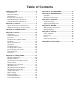
Table of Contents INTRODUCTION................................................ 2 Contact Info.................................................... 2 Manual Accuracy............................................ 2 Identification.................................................... 3 Controls & Components.................................. 4 T28780 Machine Data Sheet.......................... 5 T28781 Machine Data Sheet.......................... 7 SECTION 1: SAFETY........................................
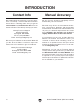
INTRODUCTION Contact Info Manual Accuracy We stand behind our machines! If you have questions or need help, contact us with the information below. Before contacting, make sure you get the serial number and manufacture date from the machine ID label. This will help us help you faster. We are proud to provide a high-quality owner’s manual with your new machine! Grizzly Technical Support 1815 W. Battlefield Springfield, MO 65807 Phone: (570) 546-9663 Email: techsupport@grizzly.
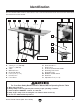
Identification Become familiar with the names and locations of the controls and features shown below to better understand the instructions in this manual. A B C D E G F H I J K L T28781 Shown O N M A. T-Slots 3⁄8", 3⁄4" (T28780) T-Slot 3⁄4" (T28781) B. Table C. Outfeed Fence D. Router Bit Guard E. Fence Lock (1 of 2) F. Infeed Fence G. Fence Base H. I. J. K. L. M. N. O.
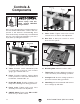
Controls & Components F To reduce your risk of serious injury, read this entire manual BEFORE using machine. G Refer to the following figures and descriptions to become familiar with the basic controls and components of this machine. Understanding these items and how they work will help you understand the rest of the manual and minimize your risk of injury when operating this machine. A B Figure 2. Router table controls (rear). F. Fence Locks.
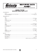
T28780 Machine Data Sheet Customer Service #: (570) 546-9663 · To Order Call: (800) 523-4777 · Fax #: (800) 438-5901 MODEL T28780 ROUTER TABLE WITH LIFT Product Dimensions: Weight ........................................................................................................................................................................... 126 lbs. Width (side-to-side) x Depth (front-to-back) x Height .................................................................................
Main Specifications: Suitable Routers for Mounting ......................................................................................... 3.25", 3.5", 4.2" Non-Plunge Routers Floor to Table Height ................................................................................................................................................. 36 - 39 in. Table Size ...............................................................................................................................................
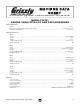
T28781 Machine Data Sheet Customer Service #: (570) 546-9663 · To Order Call: (800) 523-4777 · Fax #: (800) 438-5901 MODEL T28781 ROUTER TABLE WITH LIFT AND CAST-IRON WINGS Product Dimensions: Weight ........................................................................................................................................................................... 171 lbs. Width (side-to-side) x Depth (front-to-back) x Height ...........................................................................
Main Specifications: Suitable Routers for Mounting ......................................................................................... 3.25", 3.5", 4.2" Non-Plunge Routers Floor to Table Height ................................................................................................................................................. 36 - 39 in. Table Size ...............................................................................................................................................
SECTION 1: SAFETY For Your Own Safety, Read Instruction Manual Before Operating This Machine The purpose of safety symbols is to attract your attention to possible hazardous conditions. This manual uses a series of symbols and signal words intended to convey the level of importance of the safety messages. The progression of symbols is described below. Remember that safety messages by themselves do not eliminate danger and are not a substitute for proper accident prevention measures.
WEARING PROPER APPAREL. Do not wear clothing, apparel or jewelry that can become entangled in moving parts. Always tie back or cover long hair. Wear non-slip footwear to reduce risk of slipping and losing control or accidentally contacting cutting tool or moving parts. HAZARDOUS DUST. Dust created by machinery operations may cause cancer, birth defects, or long-term respiratory damage. Be aware of dust hazards associated with each workpiece material.
Additional Safety for Router Tables Serious cuts, amputation, entanglement, or death can occur from contact with spinning bit. Improperly secured bits or spindle parts/fasteners can fly off and strike nearby operators or bystanders with great force. Flying dust or debris from cutting operation can cause eye injuries or blindness. To minimize risk of getting hurt or killed, anyone operating router MUST completely heed hazards and warnings below. AVOIDING AMPUTATION.
SECTION 2: POWER SUPPLY Availability 110V Circuit Requirements Before installing the machine, consider the availability and proximity of the required power supply circuit. If an existing circuit does not meet the requirements for this machine, a new circuit must be installed. To minimize the risk of electrocution, fire, or equipment damage, installation work and electrical wiring must be done by an electrician or qualified service personnel in accordance with all applicable codes and standards.
Grounding & Plug Requirements This machine MUST be grounded. In the event of certain malfunctions or breakdowns, grounding reduces the risk of electric shock by providing a path of least resistance for electric current. This machine is equipped with a power cord that has an equipment-grounding wire and a grounding plug. Only insert plug into a matching receptacle (outlet) that is properly installed and grounded in accordance with all local codes and ordinances.
SECTION 3: SETUP Needed for Setup This machine presents serious injury hazards to untrained users. Read through this entire manual to become familiar with the controls and operations before starting the machine! Wear safety glasses during the entire setup process! The following items are needed, but not included, for the setup/assembly of this machine. Description Qty • Phillips Head Screwdriver #1...................... 1 • Open-End Wrench or Socket 12mm........... 1 • Straightedge 36"....................
Inventory The following is a list of items shipped with your machine. Before beginning setup, lay these items out and inventory them. If any non-proprietary parts are missing (e.g. a nut or a washer), we will gladly replace them; or for the sake of expediency, replacements can be obtained at your local hardware store. Box 2 Contents (Figure 7) Qty B. Dust Box...................................................... 1 C. Y-Fitting 4" x 4" x 21⁄ 2"................................. 1 D. Dust Hose 21⁄ 2" x 28"...
Box 3 Contents (Figure 8) Qty G. Router Bit Guard......................................... 1 H. Dust Shroud 21⁄ 2" . ...................................... 1 I. Fence Storage Brackets . ........................... 2 J. Fence Base................................................. 1 K. Infeed/Outfeed Fences................................ 2 L. Fence End Caps.......................................... 4 M. Fence Lock Shafts...................................... 2 N. Fence Lock Handles............................
Hardware Recognition Chart USE THIS CHART TO MATCH UP HARDWARE DURING THE INVENTORY AND ASSEMBLY PROCESS. Flat Head Cap Screw 5mm 5mm Model T28780 T28781 (Mfd.
Cleanup Cleanup The unpainted surfaces of your machine are coated with a heavy-duty rust preventative that prevents corrosion during shipment and storage. This rust preventative works extremely well, but it will take a little time to clean. Be patient and do a thorough job cleaning your machine. The time you spend doing this now will give you a better appreciation for the proper care of your machine's unpainted surfaces.
Site Considerations Weight Load Physical Environment Refer to the Machine Data Sheet for the weight of your machine. Make sure that the surface upon which the machine is placed will bear the weight of the machine, additional equipment that may be installed on the machine, and the heaviest workpiece that will be used. Additionally, consider the weight of the operator and any dynamic loading that may occur when operating the machine.
Assembly 4. Install (2) long braces (see Figure 14) at top of leg assemblies with (8) 5⁄16"-18 x 1⁄2" bolts and (8) 5⁄16" external tooth washers. The machine must be fully assembled before it can be operated. Before beginning the assembly process, refer to Needed for Setup and gather all listed items. To ensure the assembly process goes smoothly, first clean any parts that are covered or coated in heavy-duty rust preventative (if applicable). x8 To assemble router table: 1. 2.
7. T28781 Only: Attach right and left extension wings (see Figure 17) to router table with (6) 3 ⁄ 8 "-16 x 11⁄ 2" cap screws, (6) 3 ⁄ 8" flat washers, and (6) 3 ⁄ 8" -16 lock nuts. Note: Place level or straightedge across router table and each extension wing to ensure they are flush side to side and front to back and that the T-slots align squarely. 9. Lay straightedge across mounting plate, plate insert, and table surfaces in pattern shown in Figure 19.
13. Install (2) 1⁄4"-20 x 3 ⁄4" carriage bolts in the center slot of infeed fence (see Figure 21). Infeed Fence x2 16. Repeat Steps 13-15 to install outfeed fence on opposite side of base. 17. Align (2) holes in fence base with slots in table. Insert (2) 5⁄16" -18 T-bolts (see Figure 24) through table and fence base, as shown below. Note: Ensure T-bolts sit flush in T-slots underneath the table. Fence Base Carriage Bolts x2 Figure 21. Carriage bolts installed in infeed fence. 14.
20. Press (4) fence end caps into position, as shown in Figure 26. 23. Attach ON/OFF switch (see Figure 29) to front, righthand leg of stand with pre-installed clamp and (2) 1⁄4" -20 x 11⁄2" hex bolts and (2) 1 ⁄4" flat washers. End Caps (2 of 4) Figure 26. End caps pressed into fences. 21. Install (1) ⁄4" -20 x ⁄4" carriage bolt in top slot of infeed/outfeed fence face (see Figure 27). 1 3 x2 Carriage Bolts Outfeed Fence Infeed Fence Figure 29. Attaching ON/OFF switch to front of stand. 24.
. Attach 2 1⁄2" dust hose (see Figure 32) on dust shroud and Y-fitting. Secure with 2 1⁄2" hose clamps. Shroud Dust Hose Y-Fitting Figure 32. Dust hose installed. 27. Install fence storage brackets (see Figure 33) with (4) 5⁄16"-18 x 1⁄2" flange bolts. 28. Install crank handle storage bracket (see Figure 33) with (2) 5⁄16"-18 x 1⁄2" flange bolts.
Installing Router 1. 4. Insert crank handle in index ring on mounting plate (see Figure 3 on Page 4) and turn clockwise until lift just touches the bottom of the plate. 2. Remove lift assembly from router table and place upside down on two blocks of wood (see Figure 36) so router collet can extend through the center hole in the mounting plate. 3. Loosen (4) cap screws that secure clamp block to slide block (see Figure 36).
Connecting Power Cords Leveling Router Table To reduce risk of injury from accidental contact with spinning router bit, ALWAYS make sure router table is placed on a flat, clean surface and then leveled before router operations. The Model T28780/T28781 includes an electrical box with a 110V receptacle and an ON/OFF paddle switch (see Figure 39). The router power cord can be plugged directly into the electrical box, and the power cord on the electrical box can be plugged into a 110V outlet.
Dust Collection This machine creates a lot of wood chips/ dust during operation. Breathing airborne dust on a regular basis can result in permanent respiratory illness. Reduce your risk by wearing a respirator and capturing the dust with a dust-collection system. Recommended CFM at Dust Port: 400 CFM Do not confuse this CFM recommendation with the rating of the dust collector.
To test run router table: 1. Clear all setup tools away from router table. 2. Make sure router table paddle switch is set to OFF position. 3. Make sure router power cord is plugged into receptacle in router table electrical box. 4. Connect router table power cord to power supply. 5. Reach into dust box and turn router ON. 6. Using paddle switch, turn router table ON, verify router powers up, and then turn router table OFF. 7. 8. Try to start router with paddle switch.
SECTION 4: OPERATIONS Operation Overview To reduce your risk of serious injury, read this entire manual BEFORE using machine. Eye injuries, respiratory problems, or hearing loss can occur while operating this tool. Wear personal protective equipment to reduce your risk from these hazards. To complete a typical operation, the operator does the following: 1. Examines workpiece to make sure it is suitable for cutting. 2.
Disabling Switch The switch can be disabled by removing the key, as shown below. Disabling the switch in this manner can prevent unauthorized operation of the machine, which is important if it is not kept inside an access-restricted building or in a location where children may be present. Stock Inspection Requirements Always follow these rules when choosing and routing stock: • DO NOT cut stock that contains large or loose knots.
• Scrape all glue off the workpiece before jointing. Glue deposits on the workpiece, hard or soft, will gum up the router bit, produce poor results, and increase the risk of kickback. Squaring Fence & Table • Remove foreign objects from the workpiece. Make sure that any stock you process with the router is clean and free of dirt, nails, staples, tiny rocks, or any other foreign objects that could damage the router bit and be thrown from the machine with significant speed/force.
Adjusting Fence The fence assembly on the Model T28780/ T28781 has an infeed fence and an outfeed fence. These can be moved side to side to increase or decrease the space around the router bit. The infeed/outfeed fences are secured to the fence base with T-bolts and steel knobs (see Figure 46). Use these knobs to loosen or tighten the infeed/ outfeed fences against the base.
Adjusting Router Height The Model T28780/T28781 is equipped with a manually operated router lift that can be adjusted via the index ring in the mounting plate. 5. Underneath mounting plate, tighten lock screw jam nut (see Figure 49) against plate to secure position. Jam Nut Lock Screw To adjust router height: 1. DISCONNECT MACHINE FROM POWER! 2. Insert crank handle into index ring (see Figure 48) on mounting plate. Rocker Arm Figure 49. Location of lock screw components.
Edge Jointing 6. Jointing the edge of a board requires a straightcutting router bit to remove wood from the face of the board. The result is a perfectly flat and square edge. Place straightedge against outfeed fence, then adjust fence base so straightedge is also against bit flute (see Figure 51). Top View Straight Router Bit (Enlarged) Bit Flute Spacer Always feed workpiece against router bit rotation direction, as illustrated below.
Profile Routing To cut a profile into a workpiece: 1. DISCONNECT MACHINE FROM POWER! 2. Secure bit in router according to router manufacturer's instructions. 3. Raise router bit to desired height, then adjust fence so it sits behind the bit the same distance as desired depth-of-cut (see Figure 53). Top View Infeed Fence Outfeed Fence Bit Routing Small Stock Feeding small stock past the router bit increases the risk of kickback from the workpiece slipping into the space between the fence and bit.
Free-Hand Routing ALWAYS use hold-downs or featherboards and push sticks when shaping small or narrow stock. These devices keep your hands away from spinning router bit and sufficiently support stock to allow a safe and effective cut, reducing risk of personal injury. 6. Secure zero-clearance fence board and router bit guard to fence base, then make sure fence is parallel with table T-slot (see Squaring Fence & Table on Page 31). 7.
ALWAYS use an auxiliary jig and extreme care when free-hand routing. Routing without fence and router bit guard greatly increases risk of accidental contact with spinning router bit, causing serious personal injury. 3. Remove fence from table. 4. If possible, fabricate and mount a custom guard over the bit that safely protects your hands from spinning router bit. 5. Insert starting pin in hole on mounting plate (see Figure 57) or clamp a starting block to table (see Figure 56). To free-hand rout: 1.
SECTION 5: ACCESSORIES Basic Eye Protection Installing unapproved accessories may cause machine to malfunction, resulting in serious personal injury or machine damage. To reduce this risk, only install accessories recommended for this machine by Grizzly. T20501—Face Shield Crown Protector 4" T20502—Face Shield Crown Protector 7" T20503—Face Shield Window T20451—“Kirova” Clear Safety Glasses T20452—“Kirova” Anti-Reflective S.
SECTION 6: MAINTENANCE To reduce risk of shock or accidental startup, always disconnect machine from power before adjustments, maintenance, or service. Schedule For optimum performance from this machine, this maintenance schedule must be strictly followed. Ongoing To minimize your risk of injury and maintain proper machine operation, shut down the machine immediately if you ever observe any of the items below, and fix the problem before continuing operations: • • • • • Loose router clamping plates.
SECTION 7: SERVICE Review the troubleshooting procedures in this section if a problem develops with your machine. If you need replacement parts or additional help with a procedure, call our Technical Support. Note: Please gather the serial number and manufacture date of your machine before calling. Troubleshooting Electrical Symptom Possible Cause Possible Solution Machine does not start. 1. Switch disabling key removed. 1. Install switch disabling key (Page 30). 2.
Aligning Mounting Plate 5. Adjust set screws (see Figure 64) in mounting plate as necessary so that straightedge lies flat on table surface at all positions of pattern. Note: On Model T28781, ensure that table extension wings are flush with table edges. To ensure a workpiece does not catch on the mounting plate and cause kickback, the mounting plate must be aligned evenly with the top of the table. Tools Needed: Qty Hex Wrench 3mm............................................... 1 Open-end Wrench 12mm.....
SECTION 8: WIRING These pages are current at the time of printing. However, in the spirit of improvement, we may make changes to the electrical systems of future machines. Compare the manufacture date of your machine to the one stated in this manual, and study this section carefully. If there are differences between your machine and what is shown in this section, call Technical Support at (570) 546-9663 for assistance BEFORE making any changes to the wiring on your machine.
Wiring Diagram ON/OFF PADDLE SWITCH J1708W2 125V Hot Neutral 110 VAC 5-15 Receptacle Ground Ground Figure 65. ON/OFF switch and 110V outlet wiring. Neutral Hot 110 VAC 5-15 Plug Model T28780 T28781 (Mfd.
SECTION 9: PARTS We do our best to stock replacement parts when possible, but we cannot guarantee that all parts shown are available for purchase. Call (800) 523-4777 or visit www.grizzly.com/parts to check for availability. Table & Stand 19 20 35 36 33 34 28 32 20 5 1 12 7 1 41 12 8 26 27 25 12 17 30 29 12 12 11 41 3 12 12 41 17 13 3 12 12 41 4 2 41 41 24 39 3 18 15 21 38 23 22 12 3 16 41 12 2 12 40 37 31 10 -44- BUY PARTS ONLINE AT GRIZZLY.
Table & Stand Parts List REF PART # DESCRIPTION REF PART # DESCRIPTION 1 2 3 4 5 7 8 10 11 12 13 15 16 17 18 19 20 21 22 23 SHORT BRACE (UPPER) SHORT BRACE (LOWER) LONG BRACE LEG DUST BOX Y-FITTING 4" X 4" X 2-1/2" KNOB BOLT 1/4-20 X 1/2, 3-LOBE, D1 ADJUSTABLE FOOT 1/2-12 X 4 FENCE STORAGE BRACKET FLANGE BOLT 5/16-18 X 1/2 ROUTER LIFT CRANK HOLDER FLAT WASHER 1/4 HEX BOLT 1/4-20 X 2-1/2 PHLP HD SCR 10-24 X 3/8 PHLP HD SCR 10-24 X 5/8 DUST HOSE 2-1/2" X 28" WIRE HOSE CLAMP 2" PADDLE SWITCH J1708W2 125VA
Router Lift 104 100 124 125 122 106 120 136 117 121 115 136 108 113 114 115 132 101 102 103 111 119 107 119 105 114 113 118 110 113 119 112 109 129 127 130 126 131 116 133 134 117 128 135 REF PART # DESCRIPTION REF PART # DESCRIPTION 100 101 102 103 104 105 106 107 108 109 110 111 112 113 114 115 116 117 ROUTER LIFT ASSEMBLY MOUNTING PLATE 11-3/4" X 9-1/4" CLAMP BLOCK SLIDE BLOCK CLAMP GUIDE CLAMP GUIDE MOUNT LEADSCREW M14-1.
Fence 213 212 211 215 202 208 217 207 205 208 201 208 209 205 206 210 214 203 204 REF PART # DESCRIPTION REF PART # DESCRIPTION 201 202 203 204 205 206 207 208 DUST SHROUD 2-1/2" FENCE BASE FENCE BOARD END CAP (PLASTIC) CARRIAGE BOLT 1/4-20 X 3/4 FLAT HD SCR 1/4-20 X 5/8 HEX NUT 1/4-20 FLAT WASHER 1/4 209 210 211 212 213 214 215 217 ROUTER BIT GUARD KNOB 1/4-20, 7-LOBE, D1 FENCE LOCK SHAFT 5/16-18 X 8-1/2 STUD-DE 5/16-18 X 1/2, 6-1/4 KNOB 5/16-18, D1, BALL T-BOLT 5/16-18 X 1 FLAT WASHER 5/
Labels & Cosmetics On side of switch box. 301 306 WARNING! To reduce risk of death or serious injury, read manual BEFORE using machine. To get a new manual, call (800) 523-4777 or go to www.grizzly.com. 302 305 INJURY/SHOCK HAZARD! Disconnect power before adjustments, maintenance, or service. WARNING! INJURY HAZARD! To reduce risk of short and long-term injury, wear safety glasses, hearing protection, and a respirator when using this machine.
WARRANTY & RETURNS Grizzly Industrial, Inc. warrants every product it sells for a period of 1 year to the original purchaser from the date of purchase. This warranty does not apply to defects due directly or indirectly to misuse, abuse, negligence, accidents, repairs or alterations or lack of maintenance.