MODEL H8259 10" x 18" BENCHTOP LATHE OWNER'S Manual Copyright © October, 2007 By Grizzly Industrial, Inc. Revised July, 2009 (tr). Warning: No portion of this manual may be reproduced in any shape Or form without the written approval of Grizzly Industrial, inc.
This manual provides critical safety instructions on the proper setup, operation, maintenance and service of this machine/equipment. Failure to read, understand and follow the instructions given in this manual may result in serious personal injury, including amputation, electrocution or death. The owner of this machine/equipment is solely responsible for its safe use.
Table of Contents INTRODUCTION................................................................................................................................ 2 Foreword..................................................................................................................................... 2 Contact Info................................................................................................................................. 2 Machine Data Sheet.............................................
INTRODUCTION Foreword Contact Info We are proud to offer the Model H8259 10" x 18" Benchtop Lathe. This machine is part of a growing Grizzly family of fine woodworking machinery. When used according to the guidelines set forth in this manual, you can expect years of trouble-free, enjoyable operation and proof of Grizzly’s commitment to customer satisfaction.
MACHINE DATA SHEET Customer Service #: (570) 546-9663 · To Order Call: (800) 523-4777 · Fax #: (800) 438-5901 MODEL H8259 10" X 18" BENCH-TOP WOOD LATHE Product Dimensions: Weight................................................................................................................................................................ 73 lbs. Length/Width/Height....................................................................................................................... 36 x 11-1/2 x 15 in.
Tailstock Information Tailstock Taper.......................................................................................................................................... MT#2 Tailstock Center............................................................................................................................................Live Construction Bed Construction..................................................................................................................................
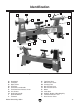
Identification A B H G I D C E J F K R L O M P Q N S T Figure 1. Model H8259 Identification. A. B. C. D. E. F. G. H. I. J. Headstock Faceplate Spur Center Tool Rest Tool Rest Lock Handle Tool Rest Base Release Lever Live Center Quill Lock Handle Quill Handwheel Tailstock Model H8259 Mfg. 10/07+ K. Tool Rest Base L. Side Access Cover M. Leveling Foot N. Belt Tension Lever O. Belt Tension Screw P. Motor Q. Lathe Bed R. ON/OFF Switch w/Disabling Key S. Tailstock Release Lever T.
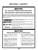
SECTION 1: SAFETY For Your Own Safety, Read Instruction Manual Before Operating this Machine The purpose of safety symbols is to attract your attention to possible hazardous conditions. This manual uses a series of symbols and signal words intended to convey the level of importance of the safety messages. The progression of symbols is described below. Remember that safety messages by themselves do not eliminate danger and are not a substitute for proper accident prevention measures.
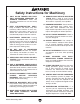
Safety Instructions for Machinery 7. 8. 9. ONLY ALLOW TRAINED AND PROPERLY SUPERVISED PERSONNEL TO OPERATE MACHINERY. Make sure operation instructions are safe and clearly understood. KEEP CHILDREN/VISITORS AWAY. Keep all children and visitors away from machinery. When machine is not in use, disconnect it from power, lock it out, or disable the switch to make it difficult for unauthorized people to start the machine. UNATTENDED OPERATION.
Additional Safety for Wood Lathes 1. KEEPING GUARDS IN PLACE. Make sure all guards are in place and that the lathe sits on a flat, stable surface. 9. 2. EYE/FACE PROTECTION. Always wear eye protection or a face shield when operating the lathe. 3. RESPIRATORY PROTECTION. Always wear a respirator when using this machine. Wood dust may cause allergies or longterm respiratory health problems. 10. ADJUSTMENTS/MAINTENANCE.
SECTION 2: CIRCUIT REQUIREMENTS 110V Operation Serious personal injury could occur if you connect the machine to the power source before you have completed the set up process. DO NOT connect the machine to the power source until instructed to do so. Electrocution or fire could result if this machine is not grounded correctly or if your electrical configuration does not comply with local and state codes.
SECTION 3: SETUP Set Up Safety This machine presents serious injury hazards to untrained users. Read through this entire manual to become familiar with the controls and operations before starting the machine! Wear safety glasses during the entire setup process! The Model H8259 is a heavy machine. DO NOT over-exert yourself while unpacking or moving your machine—get assistance. Unpacking The Model H8259 was carefully packed when it left our warehouse.
Clean Up The unpainted surfaces are coated with a waxy oil to prevent corrosion during shipment. Remove this protective coating with a solvent cleaner or degreaser, such as shown in Figure 4. For thorough cleaning, some parts must be removed. For optimum performance, clean all moving parts or sliding contact surfaces. Avoid chlorine-based solvents, such as acetone or brake parts cleaner that may damage painted surfaces. Always follow the manufacturer’s instructions when using any type of cleaning product.
Assembly Test Run Before use, the tool rest must be moved out of its shipping position and the quill handwheel knob must be attached. Once the assembly is complete, test run your machine to make sure it runs properly and is ready for regular operation. To assemble the lathe: The test run consists of verifying the following: 1) The motor powers up and runs correctly. 2) The safety paddle switch works correctly. 1. Loosen the release lever and rotate the tool rest base away from the lathe bed. 2.
SECTION 4: OPERATIONS Operation Safety Damage to your eyes, lungs, and ears could result from using this machine without proper protective gear. Always wear a face shield, respirator, and hearing protection when operating this machine. Changing Speeds To change speeds, the belt in the headstock must be adjusted. A chart on the rear of the lathe bed shows the belt positions needed to make the lathe run at the desired speed. To change speeds: 1. UNPLUG THE LATHE FROM POWER! 2.
3. Open the side and rear access covers (Figure 10). Rear Access Cover 5. Move the belt tension lever down, adjusting tension so that ½" of belt deflection is measured as shown in Figure 12, then tighten belt tension lever screw. Pulley Deflection Side Access Cover Knob Side Access Cover Figure 10. Side and rear access covers. 4. Locate the desired speed on the speed chart on the rear of the lathe bed, and move the belt to the desired grooves on the motor and spindle pulleys.
Adjusting Tailstock Adjusting Tool Rest The tailstock is equipped with a cam-action clamping system to secure it to the lathe bed. When the lever is tightened, a locking plate lifts and secures the tailstock to the bed. The tool rest base is equipped with a cam-action clamping system to secure it to the lathe bed. When the lever is engaged, a locking plate lifts up and secures the tool rest base to the bed. To position the tailstock along the bed: To position the tool rest base along the bed: 1.
Installing/Removing Spur Center The spur center installs into the headstock spindle with a taper fit. To remove the spur center: 1. Unplug lathe from power! 2. Hold the headstock spindle wheel securely while turning the faceplate counterclockwise until the spur center is forced out of the headstock spindle (Figure 16). To install the spur center: 1. Faceplate Unplug lathe from power! 2. Insert the tapered end of the center into the spindle, and push it in quickly and firmly (Figure 15).
Quill Removing/Installing Faceplate Quill Lock Handle To remove faceplate: 1. Quill Handwheel Live Center Figure 17. Installing live center in tailstock. Unplug lathe from power! 2. Hold the headstock spindle wheel securely while turning the faceplate counterclockwise until it is removed. If the spur center is installed, it will be removed during this process. Faceplate 4. Tighten the quill lock handle. To remove the live center: 1.
Selecting Turning Tools • Lathe tools come in a variety of shapes and sizes and usually fall into five major categories. • Scrapers—Mainly used where access for other tools is limited, such as hollowing operations. This is a flat, double-ground tool that comes in a variety of profiles (Round Nose, Spear Point, Square Nose, etc.) to match many different contours. Figure 21 shows an example of a round nose scraper. Gouges—Mainly used for rough cutting, detail cutting, and cove profiles.
Spindle Turning Spindle turning (Figure 23) is the operation performed when a workpiece is mounted between the headstock and the tailstock. 2. Using a wood mallet, tap the point of the spur center into the center of the workpiece, so that it leaves a center mark, then remove the spur center. 3. Using a 1⁄8" drill bit, drill a 3⁄16" deep hole at the center mark. 4. Cut the corners off your workpiece if it is over 2" x 2" to make turning safer and easier. 5.
9. Position the tool rest approximately 1⁄4" away from the workpiece and approximately 1⁄8" above the center line, as shown in Figure 26. • Turn the lathe OFF immediately if the workpiece vibrates excessively. Check to make sure the workpiece is centered and balanced. Remove the workpiece and trim excess waste off corners with a bandsaw or table saw to reduce vibration. Make sure the workpiece is securely attached in the setup.
NOTICE: Only use tap screws or wood screws with non-tapered heads (Figure 28) to attach the faceplate to the workpiece. Do NOT use drywall screws or screws with tapered heads because these can split the faceplate, or the screws may snap off during operation. Sanding/Finishing After turning, the workpiece can be sanded, as shown in Figure 30, and finished (in the same manner) before removing it from the lathe. Figure 28. Correct and incorrect screw types for mounting faceplate to workpiece.
ACCESSORIES SECTION 5: ACCESSORIES G1194—3-Jaw Chuck A "must have" for the serious wood turner. This 3-jaw chuck is a self-centering style chuck used mostly for round work. All three jaws tighten together at the same time. Jaws are reversible for expanded work holding capacity.
SECTION 6: MAINTENANCE Unpainted Cast Iron Always disconnect power to the machine before performing maintenance. Failure to do this may result in serious personal injury. Schedule For optimum performance from your machine, follow this maintenance schedule and refer to any specific instructions given in this section. Daily Check: • Loose mounting bolts. • Worn or damaged wires. • Worn switch • Any other unsafe condition.
Changing Belt To remove the old belt: 1. Open the side and rear access covers as shown in Steps 1-5 in the Changing Speeds procedure on Page 13. 2. Roll the belt off of the motor (lower) pulley (Figure 36). 5. Tap the spindle far enough out of the headstock so that the belt can be removed. A rubber or wooden mallet may be required. Take care not to damage the spindle threads. To install new belt: 1. Place the new belt over the spindle pulley. 2.
SECTION 7: SERVICE Review the troubleshooting and procedures in this section to fix or adjust your machine if a problem develops. If you need replacement parts or you are unsure of your repair skills, then feel free to call our Technical Support at (570) 546-9663. Troubleshooting Motor & Electrical Symptom Possible Cause Possible Solution Machine does not 1. Plug/receptacle is at fault or wired incor- 1. Test for good contacts; correct the wiring. start or a breaker rectly. trips. 2.
Symptom Possible Cause Possible Solution Vibration noise while machine is running; noise remains constant when speed is changed. 1. Dented fan cover on motor. 1. Replace or adjust fan cover. Inspect motor fan and replace if damaged. Motor is running but spindle is not turning. 1. Belt is loose, broken, or has come off pulleys. 1. Inspect belt and tighten, reinstall, or replace if damaged. Excessive vibration. 1. Workpiece mounted incorrectly. 1.
H8259 Wiring Diagram View this page in color at www.grizzly.com. PADDLE SWITCH (viewed from behind) Green Ground 110 VAC White Neutral Ground Wt Bk Wt Bk Black Hot 5-15 Plug Start Capacitor 24MFD 300VAC MOTOR Figure 39. Motor connections. Model H8259 Mfg. 10/07+ Figure 40. Switch connections.
-28- 32-4 32-3 61 22 56 55 32-1 32-2 55 63 62 28 56 20 25 58 57 19 58 29 15 28 26 49 48 16 28 30 59 27 14 31 16 15 32 49 51 33 11 13 38 37 35 10 12 9 34 8 39 36 7 40 41 34 53 6 44 43 42 28 5 50 45 54 46 1 2 3 4 60 Main Breakdown Model H8259 Mfg.
Main Breakdown Parts List REF PART # DESCRIPTION REF PART # DESCRIPTION 1 2 3 4 5 6 7 8 9 10 11 12 13 14 15 16 19 20 22 25 26 27 28 29 30 31 32 32-1 32-2 32-3 LATHE BED CAP SCREW M10-1.
Warning Labels Breakdown & Parts List 101 102 103 105 104 106 REF PART # DESCRIPTION REF PART # DESCRIPTION 101 102 103 ENTANGLEMENT HAZARD LABEL ELECTRICITY LABEL FACE SHIELD LABEL 104 105 106 READ MANUAL LABEL MACHINE ID LABEL SPINDLE SPEEDS LABEL PH8259101 PLABEL-14 PH8259103 PH8259104 PH8259105 PH8259106 Safety labels warn about machine hazards and ways to prevent injury. The owner of this machine MUST maintain the original location and readability of the labels on the machine.
WARRANTY CARD Name _____________________________________________________________________________ Street _____________________________________________________________________________ City _______________________ State _________________________ Zip _____________________ Phone # ____________________ Email ________________________ Invoice # _________________ Model # ____________________ Order # _______________________ Serial # __________________ The following information is given on a voluntary basis.
FOLD ALONG DOTTED LINE Place Stamp Here GRIZZLY INDUSTRIAL, INC. P.O.
WARRANTY AND RETURNS WARRANTY AND RETURNS Grizzly Industrial, Inc. warrants every product it sells for a period of 1 year to the original purchaser from the date of purchase. This warranty does not apply to defects due directly or indirectly to misuse, abuse, negligence, accidents, repairs or alterations or lack of maintenance.
Buy Direct and Save with Grizzly ® – Trusted, Proven and a Great Value! ~Since 1983~ Visit Our Website Today For Current Specials! ORDER 24 HOURS A DAY! 1-800-523-4777