4'' PROFESSIONAL CABINET SAW MODEL G7209 AND G7210 INSTRUCTION MANUAL COPYRIGHT © 1999 BY GRIZZLY INDUSTRIAL, INC. WARNING: NO PORTION OF THIS MANUAL MAY BE REPRODUCED IN ANY SHAPE OR FORM WITHOUT THE WRITTEN APPROVAL OF GRIZZLY INDUSTRIAL, INC.
WARNING Some dust created by power sanding, sawing, grinding, drilling, and other construction activities contains chemicals known to the State of California to cause cancer, birth defects or other reproductive harm. Some examples of these chemicals are: • Lead from lead-based paints. • Crystalline silica from bricks, cement, and other masonry products. • Arsenic and chromium from chemically treated lumber. Your risk from these exposures varies, depending on how often you do this type of work.
TABLE OF CONTENTS PAGE 1. SAFETY SAFETY RULES FOR POWER TOOLS ................................................................2-3 ADDITIONAL SAFETY INSTRUCTIONS FOR TABLE SAWS ................................4 SAFETY ACCESSORIES ......................................................................................5-6 COMMON DEFINITIONS, TERMS AND PHRASES ................................................7 2. CIRCUIT REQUIREMENTS 220V SINGLE-PHASE ...............................................................
SECTION 1: SAFETY For Your Own Safety Read Instruction Manual Before Operating This Equipment The purpose of safety symbols is to attract your attention to possible hazardous conditions. This manual uses a series of symbols and signal words which are intended to convey the level of importance of the safety messages. The progression of symbols is described below. Remember that safety messages by themselves do not eliminate danger and are not a substitute for proper accident prevention measures.
Safety Instructions For Power Tools 9. USE PROPER EXTENSION CORD. Make sure your extension cord is in good condition. Conductor size should be in accordance with the chart below. The amperage rating should be listed on the motor or tool nameplate. An undersized cord will cause a drop in line voltage resulting in loss of power and overheating. Your extension cord must also contain a ground wire and plug pin. Always repair or replace extension cords if they become damaged.
Additional Safety Instructions For Table Saws 1. 2. ALWAYS use blade guard, splitter and anti-kickback fingers on all ''through-sawing'' operations. Through-sawing operations are those when the blade cuts completely through the workpiece as in ripping or crosscutting. AVOID KICKBACKS. A condition in which a piece of wood is thrown back towards an operator at a high rate of speed. If you do not have a complete understanding of how kickback occurs, or how to prevent it, DO NOT operate this table saw. 3.
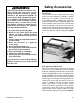
Safety Accessories Statistics prove that most common accidents among table saw users can be linked to kickback. Kickback is typically defined as the high-speed expulsion of stock from the table saw toward its operator. In addition to the danger of the operator or others in the area being struck by the flying stock, it is often the case that the operator’s hands are pulled into the blade during the kickback. The following can help minimize kickbacks. 1. Use your blade guard and splitter. 2.
Featherboard Easily made from scrap stock, featherboards provide an added degree of protection against kickback. To make a featherboard, cut a 3040° angle at one end of the board and make a number of end cuts at approximately 1⁄4" apart and 2" to 3" deep. Grizzly also offers a number of featherboards in the Grizzly catalog. See Figure 4. Figure 2. Zero Clearance Table Inserts Push Paddles Push paddles provide added leverage and support when ripping or crosscutting wide workpieces.
Common Definitions, Terms and Phrases The following is a list of common definitions, terms and phrases used throughout this manual as they relate to this table saw and woodworking in general. It is important that you read and become familiar with them before assembling, adjusting or operating this machine. Your safety is VERY important to us at Grizzly! Arbor: Metal shaft extending from the drive mechanism, to which the cutting blade is attached.
SECTION 2: CIRCUIT REQUIREMENTS 220V Single-Phase 220V Three-Phase G7209 Only: The Model G7209 has a 5 H.P., 3450 R.P.M. motor which requires a 220V single-phase circuit. The cord set included does not have a plug, as the style of plug you require will depend upon the type of service you currently have or plan to install. The motor will safely draw about 30 amps at 220V under load.
Grounding In the event of a malfunction or breakdown, grounding provides a path of least resistance for electric current to reduce the risk of electric shock. This tool is equipped with an electric cord having an equipment-grounding conductor which must be properly connected to a grounding plug. The plug must be plugged into a matching outlet that is properly installed and grounded in accordance with all local codes and ordinances.
SECTION 3: INTRODUCTION Commentary We are proud to offer the Grizzly Model G7209/10 14" Table Saw. The Model G7209/10 is part of a growing Grizzly family of fine woodworking machinery. When used according to the guidelines set forth in this manual, you can expect years of trouble-free, enjoyable operation and proof of Grizzly’s commitment to customer satisfaction. The Model G7209/10 is an industrial grade table saw intended for professional use.
Unpacking Piece Inventory The Model G7209/10 is shipped from the manufacturer in a carefully packed carton. If you discover the machine is damaged after you’ve signed for delivery, immediately call Customer Service for advice. After all the parts have been removed from their containers, you should have: When you are completely satisfied with the condition of your shipment, you should inventory its parts. The G7209/10 is a heavy machine, 1000 lbs. shipping weight.
Clean up The table and other unpainted parts of the Model G7209/10 are coated with a waxy grease that protects them from corrosion during shipment. Clean this grease off with a solvent cleaner or citrus-based degreaser such as Grizzly’s G7895 Degreaser. Do not use chlorine-based solvents – if you happen to splash some onto a painted surface, you’ll ruin the finish. Do not use gasoline or other petroleum-based solvents. They have low flash points which make them extremely flammable.
SECTION 4: ASSEMBLY Extension Wings Beginning Assembly Some metal parts may have sharp edges on them after they are formed. Please examine the edges of all metal parts before handling them. Failure to do so could result in injury. ! Inspect the extension wings for burrs or foreign material that may inhibit assembly. The mating edges of the wings and table must be clean, smooth, and flat. Use a wire brush or file if necessary to clean up the edges. The table and wings represent a very heavy load.
5. Raise or lower the rear of the wing until the wing and table are flush. Tighten the bolt. Any adjustment at this point should be minimal. 6. Check flushness at the front bolt and readjust if necessary. 7. Repeat Steps 3-4 for the other extension wing. 8. Now, check the alignment of the table and both wings with a straightedge. The straightedge should run flat across both wings and the table top. If the straightedge contacts both wings and the table evenly, you are finished with this section.
4. Attach the square fence tube to the front rail using the hex bolts and lock washers supplied. See Figure 10A. 5. Attach the fence and slide across the length of the rails to ensure smooth, accurate fence movement. Saw Blade The saw blade is extremely sharp. Use extra care when handling the blade or working near it. Serious injury is possible. Please review this section even if your saw blade came pre-installed. To install the blade: 1. Remove the table insert to gain access to the arbor. 2.
Your saw comes from the factory with a red motor bracket designed to protect the motor assembly during shipping. Remove the bracket shown in Figure 10C. Blade Guard/Splitter 1. The saw blade is extremely sharp. Use extra care when handling the blade or working near it. Serious injury is possible. 3. Slip the blade guard/splitter over the mounting bolts as shown in Figure 12. The washers should be between the bolt head and the slots. Tighten the bolts to secure the blade guard/splitter.
Setscrew and Cap Screw Adjusted rear splitter Front Support Bracket Adjustment Screws Arbor Bracket Added washers Proper Alignment Figure 17. Figure 16. Proper splitter/blade alignment. 5. Recheck guard alignment to the blade and to the table top. Adjust as necessary and tighten all the bolts before use. If the blade guard is properly aligned, please skip ahead to Step 10; otherwise, continue with the next step. 6.
Table Insert ! Disconnect power to the machine when performing any maintenance, assembly or adjustments. Failure to do this may result in serious personal injury. The table insert provides access to the blade and arbor when removed. When in place, the insert provides support for materials being cut. 1. Disconnect the power cord from the outlet. 2. Ensure that all four setscrews are firmly in contact with the table casting. 3.
SECTION 5: ADJUSTMENTS ! Blade Tilt Disconnect power to the machine when performing any maintenance, assembly or adjustments. Failure to do this may result in serious personal injury. Keep loose clothing rolled up and out of the way of machinery and keep hair pulled back. Wear safety glasses during the entire adjustment process. Failure to comply may result in serious personal injury.
Miter Slot to Blade Your table saw will give the best results if the miter slot and rip fence are adjusted parallel to the blade. If they are not exactly parallel, your cuts and finished work will be lower in quality, but more important, it increases the risk of kickback. Take the time to adjust your table saw properly. A few minutes now will be time well spent. 1. Disconnect the power cord from the outlet. Use a piece of tape to mark the blade in the gullet between two (2) teeth closest to the table. 2.
10. Refer to Figures 24 and 25, for shim placement. If the distance of A is longer than B, shim(s) will need to be placed under corners #1 and #2. If the distance of B is longer than A, shim(s) will need to be placed under corners #3 and #4. Very thin shim stock works well, just make sure they are all the same thickness, and you put an equal number under each of the two corners. 11. Tighten down one bolt a small amount and then move on to each of the others, tightening each down the same amount.
Miter Gauge Rip Fence To adjust the miter gauge so it is perpendicular to the saw blade: The rip fence included with your Model G7209/10 14" Table Saw is designed to provide excellent ripping accuracy when properly adjusted. There are three main adjustments to concern yourself with: square, parallelism and clamping pressure. 1. Loosen the lock knob on the miter gauge and place a square against the face of the miter body and the blade. 2.
Blade Alignment Setscrews The blade position can be adjusted slightly in case it contacts the table insert when raised or tilted. This adjustment can be made by moving the table, the whole trunnion assemble, or by just moving the arbor bracket. Try adjusting by moving the table first as this is the easiest way. If that doesn’t work, try adjusting the whole trunion assembly. If that still doesn’t work, try moving the arbor bracket. Nylon Pads To adjust the blade position by moving the table: Figure 28.
To adjust the blade position by moving the arbor bracket: The table and wings represent a very heavy load. DO NOT overexert yourself while lifting or moving the table and wings – get assistance. 1. Disconnect plug from power source. 2. Remove the table and wings and set them to one side. 3. Loosen the blade adjustment cap screw shown in Figure 30B. 2. Remove the table and wings and set them to one side. 4. 3.
SECTION 6: OPERATIONS Pre-Run Check Test Run Before you begin to use your Model G7209/10 14" Table Saw, you should give it a thorough inspection. While making your inspection, ask yourself the following questions: 1. Are all the fasteners tight? 2. Is the blade mounted correctly? 3. Is the saw stable? 4. Is it wired properly? 5. Is your electrical system properly configured? 6. Have you checked your work piece for obvious defects? 7.
4. If anything appears abnormal, immediately turn off the saw and fix the problem. If a problem exists that is beyond the scope of this manual, call our service department. 5. If the saw is behaving normally, turn it off and prepare to make a cut according to the instructions outlined in the following sections. 2. Cross-cut Blade: Used for cutting across the grain.
4. Plywood Blade: Used for cutting plywood or veneers. A 14" plywood blade will have 80+ teeth, a steep alternate top bevel tooth profile and very shallow gullet. See Figure 34. Flat Top Blade Alternate Top Bevel And Raker Triple Chip Blade Alternate Top Bevel Figure 35. Various saw tooth cutting profiles. Crosscutting Figure 34. Plywood blade. 5. 6. 7. Thin-kerf: Most types of saw blades are available in a thin-kerf style. Used primarily to minimize stock wastage.
workpiece fully past the blade. When a small width is to be ripped and a push-stick cannot be safely put between the blade and rip fence, rip a larger piece to obtain the desired piece. 3. Turn on the saw and allow it to reach full speed. Place the trued edge of the board against the rip fence. Feed the workpiece slowly and evenly into the blade. Do not stand behind the board as shown in Figure 37. Figure 36. Cross-cut operation. Ripping Ripping means to cut with the grain of the wood.
Dado Operations In addition to its ability to rip and crosscut lumber, the table saw is also an invaluable tool for creating a variety of dadoes. These non-through cuts can be created with a regular saw blade or with specially-designed stacking or wobbling dado blades. See Figure 38. Always use push sticks, featherboards, push paddles and other safety accessories whenever possible to increase safety and control during operations which require the blade guard and splitter to be removed from the saw.
Dadoing operations can also be accomplished using a conventional saw blade. To create a single-blade dado: 1. Clearly mark the width of the dado cut on your workpiece. Include marks on the edge of your workpiece so you can clearly identify your intended cut while the material is laying flat on the saw table. 2. Set the blade height to the depth of cut you wish to create. 3. If the dado runs the length of the material, adjust the fence so the blade is aligned with the inside of your dado channel.
Always use push sticks, featherboards, push paddles and other safety accessories whenever possible to increase safety and control during operations which require that the blade guard and splitter must be removed from the saw. ALWAYS replace the blade guard after dadoing is complete. Rabbeting operations can also be accomplished using a conventional saw blade. To create a single-blade rabbet: 1. Clearly mark the width of the rabbet cut on your workpiece.
SECTION 7: MAINTENANCE General V-Belt Regular periodic maintenance on your Model G7209/10 will ensure its optimum performance. Make a habit of inspecting your machine each time you use it. Check for the following conditions and repair or replace when necessary: To ensure optimum power transmission from the motor to the blade, the V-belts must be in good condition and operate under proper tension.
To adjust V-belt tension: 1. Loosen the motor mount bolt. 2. Shift the motor up or down to increase or decrease the V-belt tension. Tighten the motor mount bolt. 3. Check the V-belt tension again. Ensure that the motor pulley and arbor pulley are lined up. Lubrication The shielded ball bearings in the motor and throughout the Model G7209/10 require no further lubrication during their lifetime. When they do wear out, replacements can be obtained through the Grizzly Parts Department.
SECTION 8: CLOSURE The following pages contain general machine data, troubleshooting guide, parts diagram, parts list and Warranty/Return information for your Model G7209/10 Table Saw. If you need parts or help in assembling your machine, or if you need operational information, we encourage you to call the Customer Service Department. Our trained service technicians will be glad to help you.
MACHINE DATA SHEET Customer Service #: (570) 546-9663 • To Order Call: (800) 523-4777 • Fax #: (800) 438-5901 GRIZZLY MODEL G7209 14'' TABLE SAW Design Type .................................................................................................... Tilting Arbor Overall Dimensions: With Wings and Fence Rails ....................................................82" W x 47" D x 42" H Table Height .........................................................................................................
MACHINE DATA SHEET Customer Service #: (570) 546-9663 • To Order Call: (800) 523-4777 • Fax #: (800) 438-5901 GRIZZLY MODEL G7210 14'' TABLE SAW Design Type .................................................................................................... Tilting Arbor Overall Dimensions: With Wings and Fence Rails ....................................................82" W x 47" D x 42" H Table Height .........................................................................................................
5 HP Magnetic Switch -NHD Type SINGLE-PHASE 220 VOLT POWER SOURCE Disconnect power from machine before performing any electrical service. Failure to do this will result in a shock hazard leading to injury or death.
7-1/2 HP Magnetic Switch -NHD Type THREE-PHASE 220 VOLT POWER SOURCE Disconnect power from machine before performing any electrical service. Failure to do this will result in a shock hazard leading to injury or death.
329 151 152 E US D YS AN K WA DS AC AL AR KB GU KIC ES TIAN DEVIC 401 106 401 403 107 411 404 402 405 408 410 409 101 412 406 102 108 138 144 139 143 140 103 142 141 137 128A 114 133 131 138 122 126 130 123 115 132 116 110 118 134A 333 128A 332 134B 331 330 334 82 125 117 335 81 109 111 153 80 153A
221 218 225 220 231 223 227 208 219 222 224 226 208A 230 229 228 209 210 212 213 211 217 216
78 2 15 14 4 27 83 7 5 6 9 11 16 32 38 3 41 31 30 8 10 59 48 29 47 39 40 56 44 43 41 31 33 45 51 53A 50 66 52 55 54 78 15 14 65 60 3 58 57 77 56
26 28 18 21 19 1 22 24 17 62A 20 62B 24 68 72 28 62 75 61 25 23 24 70 69 74 23
207 233 201 205 206 206 204 215 214 203 202 306 308 302 301 304 303 310 311
ref 002 003 004 005 006 007 008 009 010 011 014 015 016 017 018 019 020 021 022 023 024 025 026 027 028 029 030 031 032 033 034 035 036 037 038 039 040 041 043 044 045 047 048 050 051 052 053A 054 055 056 057 058 059 060 061 062 062A 062B 066 -44- part # P7209002 P7209003 P7209004 P7209005 P7209006 P7209007 P6006 PSB31M P7209010 P7209011 P7209014 PLW05M PSS02M P7209017 P7209018 P7209019 PW02M P7209021 P7209022 P7209023 P7209024 P7209025 P7209026 P7209027 PK12M P7209029 P7209030 PN03M PB20M PB20M P7209034
REF 148 149 150 151 152 153 PART # P7209148 PLW06M PN02M PSS03M P7209152 P7209153 153A 201 202 203 204 205 206 207 208 DESCRIPTION SPACER LOCK WASHER 10MM HEX NUT M10-1.5 SET SCREW M6-1.0 X 8 DADO INSERT MOTOR KEY 8 X 8 X 30 P7209201 P7209202 P7209203 P7209204 PB03M PLW04M PFH08M P7209208 FRONT RAIL BACK RAIL SQUARE TUBE TAPE SCALE HEX BOLT M8-1.25 X 16 LOCK WASHER 8MM FLAT HD SCR M8-1.
TROUBLESHOOTING GUIDE CORRECTIVE ACTION SYMPTOM POSSIBLE CAUSE Motor will not start. 1. 2. 1. Low voltage. Open circuit in motor or loose con- 2. nections. Check power line for proper voltage. Inspect all lead connections on motor for loose or open connections. Motor will not start; fuses or 1. 2. circuit breakers blow. 1. Short circuit in line cord or plug. Short circuit in motor or loose con- 2. nections. Incorrect fuses or circuit breakers in 3. power line.
CUT HERE TO PUSH 1⁄4'' WOOD CUT HERE TO PUSH 1⁄2'' WOOD ⁄2'' GRID 1 CAUTION USE ONLY GOOD STRONG WOOD OR PLYWOOD PUSH STICK MAKE FROM 1⁄2'' OR 3⁄4'' WOOD OR THICKNESS LESS THAN WIDTH OF MAT'L TO BE CUT NOTCH TO HELP PREVENT HAND FROM SLIPPING -47- G7209/10 14'' Table Saw
WARRANTY AND RETURNS Grizzly Industrial, Inc. warrants every product it sells for a period of 1 year to the original purchaser from the date of purchase. This warranty does not apply to defects due directly or indirectly to misuse, abuse, negligence, accidents, repairs or alterations or lack of maintenance.
WARRANTY CARD Name ____________________________________________________________________________________ Street ____________________________________________________________________________________ City ______________________________________________________________State________Zip_________ Phone Number_______________________E-Mail_______________________FAX________________________ MODEL # __________________________Order #______________________________________________ The following information is given on a vol
FOLD ALONG DOTTED LINE Place Stamp Here GRIZZLY INDUSTRIAL, INC. P.O.