MODEL G0513 SERIES HEAVY-DUTY 17" BANDSAW OWNER'S Manual (Models G0513, G0513P, G0513ANV, & EXTREME MODELS G0513X2, G0513X2B, G0513X2BF, & G0513X2F) For Model G0513X2B Only Model G0513X2B Model G0513ANV Copyright © NOVEMBER, 2012 By Grizzly Industrial, Inc. Warning: No portion of this manual may be reproduced in any shape Or form without the written approval of Grizzly Industrial, inc.
This manual provides critical safety instructions on the proper setup, operation, maintenance, and service of this machine/tool. Save this document, refer to it often, and use it to instruct other operators. Failure to read, understand and follow the instructions in this manual may result in fire or serious personal injury—including amputation, electrocution, or death. The owner of this machine/tool is solely responsible for its safe use.
Table of Contents INTRODUCTION................................................ 3 Manual Accuracy............................................ 3 Contact Info.................................................... 3 G0513 Series Combination Manual................ 3 Basic Controls................................................. 4 Control Panel................................................ 4 Front Controls............................................... 4 Motor Brake...............................................
Blade Changes............................................. 48 Removing Blade......................................... 48 Installing Blade........................................... 48 Blade Speed................................................. 49 Crosscutting.................................................. 50 Resawing...................................................... 50 Cutting Curves.............................................. 51 Stacked Cuts................................................
INTRODUCTION Manual Accuracy Contact Info We are proud to offer this manual with your new machine! We've made every effort to be exact with the instructions, specifications, drawings, and photographs of the machine we used when writing this manual. However, sometimes we still make an occasional mistake. We stand behind our machines. If you have any questions or need help, use the information below to contact us. Before contacting, please get the serial number and manufacture date of your machine.
Basic Controls Refer to Figures 1–4 and the following descriptions to become familiar with the basic controls and components of your bandsaw. Knowledge of these controls and terminology will help you better understand this manual. Control Panel The 2-button power switch on Models G0513, G0513P, and G0513X2 is located on the column for easy access (see Figure 1). The power button can be disabled with a padlock to prevent unauthorized startup of the bandsaw (refer to Page 39 for additional details).
Rear Controls F. Wheel Cover Lock Knobs: Secure the wheel covers. F G G. Quick-Release Blade Tension Lever: Adjusts blade tension for quick blade changes. H. Blade Tracking Knob and Lock Lever: Moves and locks upper wheel tilt for blade tracking. I. J. Table Tilt Controls: Adjusts table tilt and locks the table in place. I Magnetic Switch: Provides thermal overload protection for the motor. K. Lower Wheel Adjustment Hub: Used when adjusting coplanarity of the wheels. L.
MODEL G0513 SERIES 17" BANDSAWS Model Number G0513/G0513P/ G0513ANV G0513X2 G0513X2B G0513X2BF G0513X2F 266 lbs. 325 lbs. 352 lbs. 357 lbs. 335 lbs. 460 lbs. 434 lbs. Product Dimensions Weight Width (side-to-side) x Depth (front-to-back) x Height 32" x 32" x 73" Footprint (Length x Width) 27" x 17 3 ⁄4" Shipping Dimensions Wood Slat Crate Type Weight Length x Width x Height 342 lbs. 418 lbs. 20" x 30" x 81" 31" x 21" x 81" 446 lbs.
Model Number G0513/G0513P/ G0513ANV G0513X2 G0513X2B G0513X2BF G0513X2F Cutting Capacities Maximum Cutting Height 12 1⁄ 8" 12 " Maximum Capacity Left of Blade 16 1⁄4" Blade Information Standard Blade Length 131 1⁄ 2" Blade Width Range 1 Blade Guides ⁄ 8"–1" Roller Disc, Ball Bearings Ball Bearings Guide Post Size 1.18" (30mm) Square Guide Post Type Square Tubing, 0.
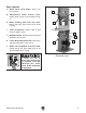
SECTION 1: SAFETY For Your Own Safety, Read Instruction Manual Before Operating This Machine The purpose of safety symbols is to attract your attention to possible hazardous conditions. This manual uses a series of symbols and signal words intended to convey the level of importance of the safety messages. The progression of symbols is described below. Remember that safety messages by themselves do not eliminate danger and are not a substitute for proper accident prevention measures.
WEARING PROPER APPAREL. Do not wear clothing, apparel or jewelry that can become entangled in moving parts. Always tie back or cover long hair. Wear non-slip footwear to avoid accidentalslips,whichcouldcauselossofworkpiececontrol. hAzARdOus dusT. Dust created while using machinery may cause cancer, birth defects, or long-term respiratory damage.
Additional Safety for Bandsaws BLADE CONDITION. Do not operate with dull, cracked or badly worn blade. Dull blades require more effort to perform the cut and increase the risk of kickback. Inspect blades for cracks and missing teeth before each use. BLADE REPLACEMENT. To avoid mishaps that could result in operator injury, make sure the blade teeth face down toward the table and the blade is properly tensioned and tracked before operating. SMALL WORKPIECE HANDLING.
SECTION 2: POWER SUPPLY Availability Before installing the machine, consider the availability and proximity of the required power supply circuit. If an existing circuit does not meet the requirements for this machine, a new circuit must be installed. To minimize the risk of electrocution, fire, or equipment damage, installation work and electrical wiring must be done by an electrican or qualified service personnel in accordance with all applicable codes and standards.
Circuit Requirements These machines are prewired to operate on a 220V power supply circuit that has a verified ground and meet the 220V operation requirements listed below. Models G0513, G0513P, G0513ANV, G0513X2, and G0513X2F can be converted to operate on a 110V power supply (refer to Voltage Conversion instructions beginning on Page 69) that has a verified ground and meet the 220V operation requirements listed below.
Improper connection of the equipment-grounding wire can result in a risk of electric shock. The wire with green insulation (with or without yellow stripes) is the equipment-grounding wire. If repair or replacement of the power cord or plug is necessary, do not connect the equipment-grounding wire to a live (current carrying) terminal. No adapter should be used with the required plug.
Extension Cords Voltage Conversion We do not recommend using an extension cord with this machine. If you must use an extension cord, only use it if absolutely necessary and only on a temporary basis. The voltage conversion MUST be performed by an electrician or a qualified service personnel. Extension cords cause voltage drop, which may damage electrical components and shorten motor life.
SECTION 3: SETUP Needed for Setup This machine presents serious injury hazards to untrained users. Read through this entire manual to become familiar with the controls and operations before starting the machine! Introduction The bandsaw is an efficient and flexible woodworking machine. However, the bandsaw functions are inter-dependent and each one must be properly set up and adjusted so that the entire machine operates correctly.
Inventory C The following is a description of the main components shipped with your machine. Lay the components out to inventory them. B If any non-proprietary parts are missing (e.g. a nut or a washer), we will gladly replace them; or for the sake of expediency, replacements can be obtained at your local hardware store. G0513, G0513P, & G0513ANV Shipping Inventory (Figures 7 & 8): Qty A. Bandsaw (not shown).................................. 1 B. Table...................................................
G0513X2, G0513X2B, G0513X2BF, & G0513X2F Shipping Inventory (Figures 9 & 10): Qty A. Bandsaw (not shown).................................. 1 B. Table............................................................ 1 C. Miter Gauge................................................. 1 D. Rear Rail..................................................... 1 E. Resaw Fence ............................................. 1 F. Front Rail..................................................... 1 G. Fence Assembly.................
Cleanup The unpainted surfaces of your machine are coated with a heavy-duty rust preventative that prevents corrosion during shipment and storage. This rust preventative works extremely well, but it will take a little time to clean. Be patient and do a thorough job cleaning your machine. The time you spend doing this now will give you a better appreciation for the proper care of your machine's unpainted surfaces.
Moving & Placing Bandsaw Using Wood Blocks 1. Move the crate to the prepared location, then remove the crate from the shipping pallet. 2. Unbolt the bandsaw from the pallet. 3. This bandsaw is a heavy machine. Serious personal injury may occur if safe moving methods are not used. Get assistance and use power equipment to move the shipping crate and remove the machine from the shipping pallet.
Mounting Assembly We recommend mounting your new machine to the floor. Because floor materials may vary, floor mounting hardware is not included. You may also mount your machine to a mobile base that has wheel locking or wheel retracting capabilities that keeps the mobile base from rolling when not in use.
4. Loosen blade tension by rotating the quickrelease tension lever clockwise, as shown in Figure 18. The table is heavy and requires two people to lift it onto the trunnions. Remove the saw blade to make table installation easier. 8. Loosen Tighten Models G0513, G0513P and G0513ANV: Secure the table to the trunnions, as shown in Figure 19 with the (4) M8-1.25 x 16 hex bolts, 8mm lock washers, and 8mm flat washers. Trunnions Figure 18. Quick-release tension lever. 5.
Installing Fence (G0513, G0513P, G0513ANV, G0513X2, & G0513X2F) 1. 4. Attach the rear rail to the table with the (2) M6-1 x 16 cap screws, as shown in Figure 20. Thread the M6-1 hex nut onto the rail pad, then thread the rail pad into the rear of the fence (see Figure 22). Rail Pad 2. Attach the front rail with the (2) M6-1 x 20 hex bolts, 6mm lock washers, and 6mm flat washers, as shown in Figure 20. Rear Rail Hex Nut x2 Figure 22. Installed rail pad. 5.
Installing Fence G0513X2BF) 1. (G0513X2B & Attach the rail plates to the front rail with the (3) M6-1 x 20 cap screws, 6mm lock washers, and 6mm flat washers (see Figure 24). 5. Install the fence on the left-hand side of the blade. 6. Place the fence flush against the bandsaw blade (see Figure 26). Front Rail Rail Plate Flat Washer 6mm Lock Washer 6mm Cap Screw M6-1 x 20 Cap Screw M8-1.25 x 20 Flat Washer 8mm Knob Lock Washer 8mm Figure 26. Fence flush with blade. Figure 24.
Installing Foot Brake (G0513X2BF & G0513X2F) Pedal Secure the foot brake pedal to the brake lever using the (2) M6-1 x 16 cap screws and 6mm lock washers, as shown in Figure 28. Brake Pedal Figure 28. Foot brake installed. Installing Resaw Fence (G0513X2, G0513X2B, G0513X2BF, & G0513X2F) To Install the resaw fence: 1. Place the 8mm flat washer on the lock handle (see Figure 29), slide it through the hole in the fence, then thread the moving plate onto the end of the lock handle threads.
Initial Blade Tracking Serious personal injury can occur if the machine starts while your hand is touching the bandsaw wheel during tracking adjustments. Disconnect power from the bandsaw before performing blade tracking adjustments. Blade tracking is primarily affected by the tilt of the upper wheel, known as “center tracking.” However, the alignment of both wheels plays an important part as well (see the Aligning Wheels instructions on Page 65 for more details).
Adjusting Positive Stop 6. Loosen the lock lever on the back of the bandsaw (see Figure 32) so that the blade tracking knob can rotate. Blade Tracking Knob The positive stop allows the table to be quickly and accurately returned to the horizontal (0˚) position after being adjusted to a different angle. To position the positive stop: 1. Lock Lever Figure 32. Blade tracking controls. 7.
Dust Collection DO NOT operate this bandsaw without an adequate dust collection system. This saw creates substantial amounts of wood dust while operating. Failure to use a dust collection system can result in short and longterm respiratory illness. Recommended CFM at Dust Port: 400 CFM Do not confuse this CFM recommendation with the rating of the dust collector.
3. Loosen the right strain relief on the junction box, then feed the cord into the box with enough slack in the wires to make the connections. 4. Re-tighten the strain relief around the cord. Tug on it to make sure the wires inside the box will not move. 5. Connect the incoming ground wire to the ground post, as shown in Figure 36. Power Supply Junction Box Ground Ground E R S Test Run Once the assembly is complete, test run your machine to make sure it runs properly and is ready for regular operation.
G0513X2B, G0513X2F, & G0513X2BF Only a. Insert the key into the power switch (see Figure 37), then turn it to the "1". e. Push the OFF button in, then twist it clockwise so it pops out. When the OFF button pops out, the switch is reset and ready for operation (see Figure 38). Power Switch ON Button OFF Button OFF Button Figure 38. Resetting the OFF button. f. Turn the key in the power switch to "0". Figure 37. G0513X2B and G0513X2BF control panel. b.
Tensioning Blade 4. Engage the blade tension quick-release lever to apply tension to the blade (see Figure 39). A properly tensioned blade is essential for making accurate cuts, maximizing the life of the blade, and making other bandsaw adjustments. However, it will not compensate for cutting problems caused by too rapid of a feed rate, hardness variations between workpieces, and improper blade selection.
Deflection Method The deflection method is more subjective than the flutter method. Each blade deflects differently and every user must determine what "moderate pressure" means. The following are general guidelines for tensioning the blade with the deflection method. To tension the bandsaw blade: 1. DISCONNECT BANDSAW FROM POWER! 2. Make sure the blade is properly tracking as instructed in the Initial Blade Tracking section on Page 25. 3.
Adjusting Blade Support Bearings Support bearings stop excessive backward deflection of the blade from the advancing workpiece. The proper adjustment of the support bearings is an important part of making accurate cuts and prevents damage to the blade teeth from contact with the blade guides. It is important that the distance of the support bearing behind the blade is the same as the distance of the blade guides behind the teeth gullets, which is typically about 0.016" (see Figure 41).
A. Support Bearing. Stops excessive backward blade deflection from the pressure of the advancing workpiece. Note: The flat surface of the upper support bearing faces the blade. The round edge of the lower support bearing faces the blade. B. Upper Support Bearing Shaft. Mounts the support bearing behind the blade. When the support bearing shaft cap screw is loose, move this shaft by hand to adjust the upper support bearing approximately 0.
Adjusting Blade Guides (G0513, G0513P, & G0513ANV) 3. Tools Needed Qty Hex Wrench 5mm............................................... 1 Feeler Gauge 0.004"................................. 1 Each 0.016" Crisp Dollar Bill (Optional).................................. 1 Gap Blade Fine Ruler........................................................... 1 By hand, adjust the distance of the guides approximately 0.
5. By hand, slide the guide block to position the blade guides approximately 0.016" behind the teeth gullets (see Figure 47), then retighten the guide block cap screw to secure the setting. Blade Guide 0.016" Gap Adjusting Blade Guide Bearings (G0513X2, G0513X2B, G0513X2BF, & G0513X2F) Tools Needed Qty Hex Wrench 5mm............................................... 1 Feeler Gauge 0.004", 0.016"..................... 1 Each Crisp Dollar Bill (Optional)..................................
3. Loosen the lateral rod cap screw and slide the guide block to position the blade guides approximately 0.016" behind the blade gullets, as illustrated in Figure 50. Note: The 0.016" spacing is ideal, although with larger blades it may not be possible. In such cases, adjust the guide bearings as far forward as possible to the blade gullets, and still maintain the proper support bearing spacing adjustment.
— If the distance is not the same at the front and back of the table, adjust the table until it is. 6. Place a square on the table and against the back of the blade, as shown in Figure 52. The table should be perpendicular to the back of the blade. 4. Loosen the four cap screws located on the top face of the fence (see Figures 53–54).
1. DISCONNECT BANDSAW FROM POWER! Calibrating Miter Gauge 2. Make sure the table is aligned with the blade (see Aligning Table on Page 36 for detailed instructions). The miter gauge needs to be calibrated to the blade when it is first mounted in the miter slot. Aligning Fence G0513X2BF) (G0513X2B & 3. Install the fence and lock it in place next to the miter slot. Qty Tool Needed Phillips Screwdriver #2....................................... 1 4.
SECTION 4: OPERATIONS Damage to your eyes and lungs could result from using this machine without proper protective gear. Always wear safety glasses and a respirator when operating this machine. Disabling & Locking Switch (G0513, G0513P, G0513ANV, G0513X2) The switch can be disabled and locked by inserting a padlock through the power button, as shown in Figure 58.
Disabling & Locking Switch (G0513X2B, G0513X2BF, G0513X2F) General Overview The bandsaw is one of the most versatile wood cutting tools in the shop. It is capable of performing many different cutting functions including: Straight Cuts The power switch can be disabled and locked by removing the key, as shown. Locking the switch in this manner can prevent unauthorized operation of the machine, which is especially important if the machine is not stored inside an accessrestricted building.
Operation Overview The purpose of this overview is to provide the novice machine operator with a basic understanding of how the machine is used during operation. Due to the generic nature of this overview, it is not intended to be an instructional guide. To learn more about specific operations, read this entire manual and seek additional training from experienced machine operators, and do additional research outside of this manual by reading "howto" books, trade magazines, or websites.
Table Tilt Models G0513X2, G0513X2B, G0513X2BF, & G0513X2F Model Tilt Specifications G0513, G0513P, G0513ANV...... 10° left, 45° right G0513X2...................................... 5° left, 45° right G0513X2B................................... 5° left, 45° right G0513X2BF................................. 5° left, 45° right G0513X2F....................................
Guide Post Fine Tune Tracking The guide post connects the upper blade guide assembly to the bandsaw. The guide post allows the blade guide assembly to move up or down so that it is as close to the workpiece as possible for safety and blade support. During setup, the blade was tracked without the machine connected to power. In this procedure, the bandsaw is turned ON to perform fine tuning of the tracking. Make small changes with the blade tracking knob as you monitor the effect on the blade tracking.
Blade Selection Selecting the right blade for the cutting task requires knowledge about blade characteristics and cutting priorities (i.e. speed, finish, etc.). Blade Terminology D G Blade Width A C Blade Material H F Measured by the blade circumference, blade lengths are specific to each bandsaw. They are determined by the wheel diameter and distance between the wheels.
Bimetal Blade: A strip of high-speed tool steel is precision welded to a flexible carbon blade, then teeth are ground into the blade to provide good edge-holding qualities for blades taking a lot of abuse (see Figure 65). Carbon Steel Blade Alternate: An all-purpose arrangement where the teeth are bent evenly left and right of the blade. Raker: Three teeth in a recurring group—one bent left, one bent right, and then one that is not bent. The raker set is ideal for most contour cuts.
Blade Selection Chart Use the blade selection chart below as a general guide when selecting a blade for your operation.
Blade Breakage Many conditions may cause a bandsaw blade to break. Blade breakage is unavoidable in some cases, since it is the natural result of the peculiar stresses that bandsaw blades must endure. Blade breakage is also due to avoidable circumstances. Avoidable blade breakage is most often the result of poor care or judgement on the part of the operator when mounting or adjusting the blade or support guides.
Blade Changes Blade changes entail removing the existing blade from the wheel and table, installing the new blade, then properly adjusting the blade tension and tracking. Installing Blade 1. DISCONNECT BANDSAW FROM POWER! 2. Slide the blade through the table slot, ensuring that the teeth are pointing down toward the table. Note: If the teeth will not point downward in any orientation, the blade is inside-out. Remove the blade, and twist it right side-out. Removing Blade 1.
Blade Speed 3. Refer to Figure 71 to locate the correct V-belt position for the desired blade speed and move the V-belt to the indicated pulleys. The blade speed can be adjusted to 1700 or 3500 FPM. Speed adjustments are made by moving the V-belt position on the motor and wheel pulleys. BANDSAW WHEEL Most woodcutting can be performed successfully at the higher blade speeds.
Crosscutting Resawing Crosscutting is the process of cutting across the grain of wood. For plywood and other processed wood, crosscutting simply means cutting across the width of the material. Resawing (see Figure 74 for an example) is the process of cutting a board into two or more thinner boards. The maximum board width that can be resawn is limited by the maximum cutting height of the bandsaw. To make a 90˚ crosscut: 1. Mark the workpiece on the edge where you want to begin the cut. 2.
To resaw a workpiece: 1. Verify that the bandsaw is setup properly and that the table is perpendicular to the blade. 2. Use the widest blade your bandsaw will accept. Note: The blade must also be sharp and clean. 3. Install the resaw fence, set it to the desired width of cut, and lock it in place. Note: When resawing thin workpieces, set up the resaw fence in the alternate position, as shown in Figure 75, and make sure to use a push stick.
Stacked Cuts One of the benefits of a bandsaw is its ability to cut multiple copies of a particular shape by stacking a number of workpieces together. Before making stacked cuts, ensure that both the table and the blade are properly adjusted to 90°. Otherwise, any error will be compounded. 4. Make relief cuts perpendicular to the outline of your intended shape in areas where changes in blade direction could strain the woodgrain or cause the blade kerf to bind. 5.
ACCESSORIES SECTION 5: ACCESSORIES Some aftermarket accessories can be installed on this machine that could cause it to function improperly, increasing the risk of serious personal injury. To minimize this risk, only install accessories recommended for this machine by Grizzly. D2057A—Heavy-Duty SHOP FOX® Mobile Base This patented base is the most stable on the market with outrigger type supports. Adjusts from 20" x 201⁄2" to 291⁄2" x 291⁄2". 700 lb. capacity. Weighs 47 lbs.
T20388—Success with Bandsaws Book Explore the many creative possibilities of floorstanding and portable bench-top bandsaws. With these practical instructions and color photographs, woodworkers can quickly master basic skills and then practice advanced procedures like making dovetail, mortise and tenon joints and cutting variable-curve edges— even make their own moneysaving jigs and templates. 176 pages.
SECTION 6: MAINTENANCE Always disconnect power to the machine before performing maintenance. Failure to do this may result in serious personal injury. Schedule For optimum performance from your machine, follow this maintenance schedule and refer to any specific instructions given in this section. Daily Check: • Loose mounting bolts. • Worn or damaged saw blade. • Worn or damaged wires. Check/clean wheel brush. • Clean/protect table surface. • • Check lubrication points. • Any other unsafe condition.
3. Using a rag and mineral spirits, wipe off any existing grease and sawdust build-up on the rack (see Figure 83). 4. Apply a thin coat of lubricant to the tension adjustment assembly and tension lever cam (see Figure 84). Cam Adjustment Assembly Rack Exposed for Lubrication Figure 83. Example of rack lubrication location. 4. Apply a thin coat of lubricant to the rack. 5.
SECTION 7: SERVICE Review the troubleshooting and procedures in this section if a problem develops with your machine. If you need replacement parts or additional help with a procedure, call our Technical Support at (570) 546-9663. Note: Please gather the serial number and manufacture date of your machine before calling. Troubleshooting Symptom Possible Cause Possible Solution Machine does not start or a breaker trips. 1. Stop button engaged/at fault. 2. Switch disabling key removed. 3.
Symptom Possible Cause Possible Solution Machine stalls or slows when operating. 1. Too much pressure against workpiece. 2. Workpiece too moist or unsuitable. 3. Workpiece is warped. 4. Fence incorrectly adjusted. 5. V-belt slipping. 1. Decrease the feed rate or workpiece pressure. 2. Only cut wood and ensure moisture is below 20%. 3. Straighten workpiece or use a different one. 4. Adjust/calibrate fence (Page 37). 5. Tension/replace V-belt (Page 60); ensure pulleys are aligned. 6. Test/repair/replace.
Symptom Possible Cause Blade wears on one 1. Blade contacting table insert. side, slows, smokes or shows signs of overheating. 2. Blade guides are mis-adjusted or worn. 3. Blade has insufficient support near cutting area. 4. Blade installed backwards. 5. Too much side pressure when feeding workpiece. 6. Wheels are out of alignment. 7. Dull or incorrect blade for workpiece. 8. Blade is bell-mouthed. 9. Fence not parallel with blade (pressure at blade backside). 10. Table top is not square with blade.
V-Belt Service Checking V-Belt To ensure optimum power transmission from the motor to the blade, the V-belt must be in good condition and properly tensioned. The belt should be free of cracks, fraying, and wear. Belt tension and condition should be checked at least every 3 months—more often if the bandsaw is used daily. To replace the V-belt: 1. DISCONNECT BANDSAW FROM POWER! 2. Open both wheel covers, and remove the blade (refer to Blade Changes on Page 48). 3.
Blade Lead "Blade Lead" means that the blade does not cut straight when using the fence or miter gauge (see Figure 89). This is a common condition with all bandsaws. Worn or damaged blades may cause lead and replacing them will fix the problem. Still, if your bandsaw is setup correctly and lead occurs, compensate for it by skewing the fence. 2. Slide the fence out of the way and cut freehand along the line. Stop at the halfway point. Turn the bandsaw OFF and wait for the blade to come to a complete stop.
Adjusting Wheel Brush Adjusting Tension Lever The lower wheel has a brush, as shown in Figure 90, that is designed to sweep sawdust off the wheel tire as the wheel rotates. In order to work properly, the brush must make firm contact with the wheel. The quick-release tension lever was setup at the factory for use with the pre-installed 131 1⁄ 2" blade.
Adjusting Guide Post Travel The guide post assembly should remain parallel with the blade front-to-back and side-to-side along its length of travel. If it does not, follow these instructions to adjust it. Important: Make sure the table is aligned with the blade from side-to-side and front-to-back before beginning these procedures (refer to Aligning Table on Page 36 for detailed instructions). —If there is no gap between the square and the guide post along its full length, no adjustments need to be made.
1. DISCONNECT BANDSAW FROM POWER! 2. Loosen the guide post lock knob, lower the blade guide assembly to within 1" of the table top, then tighten the lock knob. 3. Remove the screws that secure the guide post guard and move it up and out of the way. Measure the distance "A" between the upper front face of the guide post rack and the back of the blade (see Figure 94).
Aligning Wheels 3-1⁄2" Components and Hardware Needed: Qty 56" Long 2x4...................................................... 1 Tools Needed: Hex Wrenches 4 & 6 mm..............................1 Ea Wrench 13mm.................................................... 1 Tape Measure..................................................... 1 Coplanarity Gauge (see Figure 96)................... 1 Straightedge......................................................... Fine Ruler...........................................
—If the wheels are coplanar (Figure 99, A), the straightedge will evenly touch the top and bottom of both wheels. — If the straightedge does not touch both wheels evenly, the upper wheel needs to be shimmed (Figure 99, D) or the lower wheel needs to be adjusted (Figure 99, C).
8. Magnetic Brake Adjustment (G0513X2B, G0513X2BF) When the wheels are coplanar, place a mark on each wheel where you held the straightedge. This assures repeated accuracy every time you adjust your wheels. Note: When wheels are properly coplanar, the blade may not be centered on the crown of the wheel, but it will be balanced. Adjusting Lower Wheel Only do this procedure if you cannot make the wheels coplanar with the tracking knob or by shimming the upper wheel.
machine SECTION 8: WIRING These pages are current at the time of printing. However, in the spirit of improvement, we may make changes to the electrical systems of future machines. Compare the manufacture date of your machine to the one stated in this manual, and study this section carefully. If there are differences between your machine and what is shown in this section, call Technical Support at (570) 546-9663 for assistance BEFORE making any changes to the wiring on your machine.
G0513, G0513P, G0513ANV, & G0513X2 Wiring Diagram Ground Neutral Power Switch (viewed from behind) POTS Ground G 110 VAC Rewired to 110V TRATS Hot R. Cap 40M 250V S. Cap 300M 250V L5-30 Plug (As Recommended) Ground G Hot 220 VAC 220 VAC Hot 6-15 Plug (As Recommended) 1 4 Ground W 3 2 Motor @220V Rewired to 110V R. Cap 40M 250V S.
G0513X2B Wiring Diagram Ground Hot L2 G 220 VAC 6-15 PLUG Hot L1 Ground R CONTROL PANEL (viewed from behind) S L1/1 L2/3 NO13 L3/5 SDE MA-18 NC15 SDE NC16 Ground A U T2/4 AMP SDE RA-20 8-12 1/2 3/4 5/6 12 96 U 14 RWP 21 13 NO14 T3/6 RESET Rectifier PU-23-2 T1/2 22 22 8 14 10 NO 21 13 98 V 95 22 14 MAGNETIC SWITCH FFO 21 13 Ground U V Magnetic Brake YZG 220V MOTOR Run Capacitor 45MFD 450VAC -70- READ ELECTRICAL SAFETY ON PAGE 68! G0513 Series Bandsaws
G0513X2BF Wiring Diagram Ground Power Supply Junction Box Ground Ground E G Hot R S 220 VAC Hot 220V 6-15 Plug (As Recommended) Magnetic Switch Assembly A Control Panel (Viewed from Behind) S R 22 E Power 13 14 L1/1 L2/3 L3/5 NO13 Ground Contactor SDE MA-18 Rectifier PU-23-2 21 Foot Brake Switch NC15 NC16 22 T2/4 T3/6 OL Relay SDE RA-20 1/2 3/4 ON E NO14 U 13 Lb 8 22 95 10 96 21 Set at 10A 5/6 12 14 RESET T1/2 98 14 21 OFF 13 V E Motor E U V Ground Magneti
G0513X2F 220V Wiring Diagram Ground Power Supply Junction Box Ground Ground E G Hot R S 220 VAC Hot 220V 6-15 Plug (As Recommended) Magnetic Switch Assembly A Control Panel (Viewed from Behind) 1 S R L1/1 L2/3 L3/5 22 E 2 Power 1 Ground Conctactor SDE MA-09 NC15 NC16 22 T1/2 T2/4 T3/6 Foot Brake Switch 13 14 NO13 21 21 ON E NO14 13 14 3 3 1/2 3/4 5/6 RESET 2 OL Relay SDE RA-20 Set at 10A 8 12 U 22 95 10 96 98 14 2 V 3 1 3 E 21 OFF 13 2 1 E U V 2
G0513X2F 110V Wiring Diagram Power Supply Junction Box Ground Ground Ground E Neutral R S W G 110 VAC Magnetic Switch Assembly A Control Panel (Viewed from Behind) L5-30 Plug (As Recommended) 1 S R L1/1 L2/3 L3/5 22 E 2 Power Foot Brake Switch 13 14 NO13 21 1 Ground Conctactor SDE MA-18 NC15 NC16 22 T1/2 T2/4 T3/6 21 ON E NO14 13 14 3 3 1/2 3/4 5/6 RESET 2 OL Relay SDE RA-30 18 26 Set at 20A U 22 95 22 98 96 14 2 V 3 3 1 21 OFF 13 2 1 E E U V Lb
-74- 23 22 21 22 48 24 21 26 17 17 18 24 20 19 16 15 14 13 50 25 18 27 20 18 44 28 29 11 8 31 43 41 39 40 30 36 42 37 38 176 39 45 46 9 12 11-1 49 47 10 61 32 33 34 35 175 17 55 55A 61 5 58 4 57 56 61 64 88 61 65 66 152 60 87 39 62 48 50 67 60 152 63 68 69 72 70 59 71 95 94 93 82-8 82-3V2 82-9 91 92 86 78 85 90 84 83 82V2 82-7V2 82-9A 82-10 82-11 82-2V2 83 61 89 84 80 79 39 75 119 97 81 76 74 73 82-5V2 82-1V2 8
G0513/G0513P/G0513ANV Main Parts List REF PART # DESCRIPTION REF PART # DESCRIPTION 4 5 5 5 8 9 10 11 12 13 14 15 16 17 18 19 20 21 22 23 24 25 26 27 28 29 30 31 32 33 34 35 36 37 38 39 40 41 42 43 44 45 46 47 48 49 50 55 55 55 55A 55A 55A 56 57 LIFTING EYE BOLT M10-1.5 MACHINE BODY (G0513) MACHINE BODY (G0513P) MACHINE BODY G0513ANV) FLAT WASHER 6MM POWER CORD 14G 3W 72" HEX NUT M6-1 POINTER STEP SCREW M4-.
G0513/G0513P/G0513ANV Table, Trunnion, & Lower Blade Guides 127 124 115 117 112 119 118 113 113 120 116 128 126 129 114 115 148 130 121 122 123 135 99 100 96 133 103 139 163 116 131 109 110 111 101 77 132 107 108 103 104 102 105 106 134 98 REF PART # DESCRIPTION REF PART # DESCRIPTION 77 96 98 99 100 101 102 103 104 105 106 107 108 109 110 111 112 113 114 115 116 117 LOCK WASHER 8MM FLAT WASHER 8MM CAP SCREW M10-1.5 X 35 HEX NUT M10-1.
G0513/G0513P/G0513ANV Fence 216 211 202 218 220 212 204 207 208 222 213 215 209 225 222 210 205 203 226 227 223 220 217 125 206 221 214 219 201 REF PART # DESCRIPTION REF PART # DESCRIPTION 125 201 202 203 204 205 206 207 208 209 210 211 212 213 FENCE ASSEMBLY W/RAILS FRONT FENCE RAIL FENCE BASE ALIGNMENT SHAFT LOCK BLOCK SHAFT SPRING PLATE SPACER PLATE FENCE SLEEVE FENCE LOCK HANDLE RAIL PAD CONVEX WINDOW CAP SCREW M6-1 X 55 LOCK CAM 214 215 216 217 218 219 220 221 222 223 225 226 227
G0513/G0513P/G0513ANV Upper Blade Guides & Miter Gauge 163 164V2 165 162 174 166 157A 161V2 160 167 142 168 159 140 169 158 6 170 141 157 163 171 136 137 151 172 149 155 154 156 153 138 144 149 150 138-1 192 149 143 145 146 134 193 147 194 173-5 173-4 173-6 173 173-2 173-9 173-3 173-1 173-8 173-7 -78- G0513 Series Bandsaws
G0513/G0513P/G0513ANV Upper Blade Guides & Miter Gauge Parts List REF PART # DESCRIPTION REF PART # DESCRIPTION 6 134 136 137 138 138 138-1 140 141 142 142 143 144 145 146 147 149 150 151 153 154 155 156 157A 157 158 159 PSS07M P0513134 PCAP148M PW01M P0513138 P0513ANV138 P0513138-1 P0513012 P0513141 P0513142 P0513ANV142 PR05M P6202ZZ P0513145 P0513133 PTS001M PCAP28M P0513150 P0513151 P0513153 PS38M PN04M P0513156 P0513157A P0513157 P0513158 PB08M SET SCREW M5-.
G0513 Labels 186 185 184 177 182 179 189 181 180 190 178 178 188 183 187 182 REF PART # DESCRIPTION REF PART # DESCRIPTION 177 178 179 180 181 182 183 MACHINE ID LABEL ELECTRICITY LABEL SAFETY GLASSES LABEL READ MANUAL LABEL HANDS/BS BLADE LABEL DONT OPEN LABEL UNPLUG BANDSAW LABEL 184 185 186 187 188 189 190 G8589 P0513185 P0513186 PPAINT-1 PPAINT-10 P0513189 P0513190 GRIZZLY NAMEPLATE- LARGE SAW TENSION LABEL MODEL NUMBER LABEL GRIZZLY GREEN TOUCH-UP PAINT LIGHT GRAY REF PAINT GUIDE POST
G0513P Labels 186 182 184 189 177 179 181 180 178 188 183 191 182 192 187 REF PART # DESCRIPTION REF PART # DESCRIPTION 177 178 179 180 181 182 183 MACHINE ID LABEL ELECTRICITY LABEL SAFETY GLASSES LABEL READ MANUAL LABEL HANDS/BS BLADE LABEL DONT OPEN LABEL UNPLUG BANDSAW LABEL 184 186 187 188 189 191 192 G8589 P0513P186 PPAINT-01 PPAINT-24 P0513189 PLABEL-75 P0513P192 GRIZZLY NAMEPLATE- LARGE MODEL NUMBER LABEL GRIZZLY GREEN TOUCH-UP PAINT PB WHITE TOUCH-UP PAINT GUIDE POST ADJUST LABEL P
G0513ANV Labels 192 189 191 182 185 179 181 188 180 178 183 177 182 193 194 187 186 REF PART # DESCRIPTION REF PART # DESCRIPTION 177 178 179 180 181 182 183 185 MACHINE ID LABEL ELECTRICITY LABEL SAFETY GLASSES LABEL READ MANUAL LABEL HANDS/BS BLADE LABEL DONT OPEN LABEL UNPLUG BANDSAW LABEL SAW TENSION LABEL 186 187 188 189 191 192 193 194 P0513ANV186 P0513ANV187 P0513ANV188 P0513189 P0513ANV191 P0513ANV192 P0513ANV193 P0513ANV194 MODEL NUMBER LABEL BLACK TOUCH-UP PAINT ORANGE TOUCH-UP PAIN
G0513 Series Bandsaws 23 22 17-1 17 48 17-2 21 55 22 24 21 17-5 17-4 17-2 18-5 24 17-3 7 14 13 49 18-1 2 47 61 18 11 29 25 30 40 43 8 31 39 39 44 9 36 42 37 38 3 45 46 10 12 50 18-2 18-3 18-3 18-4 34 35 28 32 33 18-2 16 15 55A 41 5 61 58 4 57 61 56 64 88 65 48 67 87 39 63 50 68 111 60 61 62 111 60 66 59 70 76 75 74 73 72 81 82-8 83 93 97 91 92 90 84 83 82V2 82-11 82-5V2 85 82-10 86 78 95A 94 61 89 119 84
G0513X2 Main Parts List REF PART # DESCRIPTION REF PART # DESCRIPTION 2 3 4 5 7 8 9 10 11 12 13 14 15 16 17 17-1 17-2 17-3 17-4 17-5 18 18-1 18-2 18-3 18-4 18-5 21 22 23 24 25 28 29 30 31 32 33 34 35 36 37 38 39 40 41 42 43 44 45 46 47 48 49 50 55A SET SCREW M6-1 X 10 BUSHING LIFTING EYE BOLT M10-1.5 MACHINE BODY BUSHING FLAT WASHER 6MM POWER CORD 14G 3W 72" HEX NUT M6-1 POINTER STEP SCREW M4-.
G0513X2 Labels 201 216 205 214 202 215 203 204 206 208 209 207 210 211 209 212 213 REF PART # DESCRIPTION REF PART # DESCRIPTION 201 202 203 204 205 206 207 208 MODEL NUMBER LABEL GRIZZLY LOGO PLATE OPEN DOOR LABEL GUARD ADJ LABEL SCALE DIRECTIONS LABEL SAFETY GLASSES LABEL HANDS/BLADE LABEL READ MANUAL LABEL 209 210 211 212 213 214 215 216 ELECTRICITY LABEL EXTREME SERIES PLATE DISCONNECT POWER LABEL OPEN DOOR LABEL PUTTY TOUCH-UP PAINT TENSION ADJ LABEL GRIZZLY GREEN TOUCH-UP PAINT MACHIN
-86- 55A 23 48 55 22 17-2 21 17-1 17 177 19-7 19-8 19-8 19-5V2 22 176 24 21 17-5 17-4 17-2 18-5 24 17-3 16 15 14 13 19-6V2 19 18-2 18-1 19-1 8 19-2 19-3 18 30 19-9 25 29 28 38 40 37 41 46 45 44 31 36 51 3 11 18-2 18-3 18-3 18-4 12 47 10 32 33 34 35 2 7 49 61 50 5 61 82-10 82-11 82-3 82-9 59 69 70 82-13 82-14 111 60 62 87 61 111 60 48 50 67 66 63 39 68 82-4 82-5V2 82-12 65 64 88 57 56 82-2 58 61 4 76 81 82-15 82-6 95 94 61 93 85
G0513X2B Main Parts List REF PART # DESCRIPTION REF PART # DESCRIPTION 2 3 4 5 7 8 10 11 12 13 14 15 16 17 17-1 17-2 17-3 17-4 17-5 18 18-1 18-2 18-3 18-4 18-5 19 19-1 19-2 19-3 19-5V2 19-6V2 19-7 19-8 19-9 21 22 23 24 25 28 29 30 31 32 33 34 35 36 37 38 39 40 PSS01M P0513X003 P0513004 P0513005 P0513X007 PW03M PN01M P0513011 P0513012 P0513013 PRP91M P0513015 P0513016 P0513X2B017 P0513017 P6204-2RS PR25M P0513X019 T23071 P0513X2B018 P0513017 P6204-2RS PR25M P0513X027 T23071 P0513X2B019 P0513X2B019-1 P
G0513X2B Main Parts List REF PART # DESCRIPTION REF PART # 86 87 88 89 90 91 92 93 BUTTON HD CAP SCR M8-1.25 X 20 STRAIN RELIEF PLATE 1-HOLE FLANGE SCREW M5-.8 X 10 PILLOW BLOCK KEY 5 X 5 X 35 KEY 5 X 5 X 35 MOTOR PULLEY TYPE-A 3.
G0513X2B Labels 201 216V2 205 214 202 203 215 204 206 208 207 209 210 211 212 213 REF PART # DESCRIPTION REF PART # DESCRIPTION 201 202 203 204 205 206 207 208 MODEL NUMBER LABEL GRIZZLY LOGO PLATE OPEN DOOR LABEL GUARD ADJ LABEL SCALE DIRECTIONS LABEL SAFETY GLASSES LABEL HANDS/BLADE LABEL READ MANUAL LABEL 209 210 211 212 213 214 215 216V2 PLABEL-14 P0513X210 PLABEL-18 PLABEL-20 PPAINT-11 P0513X214 PPAINT-1 P0513X2B216V2 ELECTRICITY LABEL EXTREME SERIES PLATE DISCONNECT POWER LABEL OPEN
48 55 -90- 95 23 22 94 61 17-2 21 17-1 24 17-3 61 49 50 17 22 24 18-5 21 17-5 17-4 17-2 55A 35 18-2 18-1 11 45 44 12 18 18-2 18-3 37 25 29 36 30 46 51 3 41 38 40 2 10 28 18-3 18-4 7 32 33 34 14 15 16 13 47 8 31 5 58 61 4 67 66 76 57 56 93 119 111 61 60 97 91 92 90 19-4 82-10 82-5 82-9 89 84 82-3 82-15 86 85 78 39 83 19 19-6 74 73 75 72 82-2 50 80 79 48 81 60 111 61 65 63 62 39 88 64 87 68 69 70 59 71 174 82-4 82 19-2 19-1
G0513X2BF Main Parts List REF PART # DESCRIPTION REF PART # DESCRIPTION 2 3 4 5 7 8 10 11 12 13 14 15 16 17 17-1 17-2 17-3 17-4 17-5 18 18-1 18-2 18-3 18-4 18-5 19 19-1 19-2 19-3 19-4 19-5 19-6 21 22 23 24 25 28 29 30 31 32 33 34 35 36 37 38 39 40 41 44 45 SET SCREW M6-1 X 10 BUSHING LIFTING EYE BOLT M10-1.5 MACHINE BODY BUSHING FLAT WASHER 6MM HEX NUT M6-1 POINTER STEP SCREW M4-.
G0513X2BF Main Parts List REF PART # DESCRIPTION REF PART # DESCRIPTION 93 94 95 97 111 119 171 V-BELT A42 CAP SCREW M6-1 X 10 LOWER WHEEL COVER FENDER WASHER 8MM CAP SCREW M6-1 X 20 LOCK WASHER 8MM FLANGE SCREW M5-.8 X 10 172 173 174 175 177 178 CORD CLIP 5/16" FLANGE SCREW M5-.8 X 50 PHLP HD SCR M4-.
G0513X2BF Labels 201 214 202 203 204 216 205 206 208 207 209 209 211 215 207 213 REF PART # DESCRIPTION REF PART # DESCRIPTION 201 202 203 204 205 206 207 MODEL NUMBER LABEL NAMEPLATE-LARGE DON'T OPEN DOOR LABEL GUARD ADJUSTMENT LABEL SCALE DIRECTIONS LABEL SAFETY GLASSES LABEL HANDS/BLADE HAZARD LABEL 208 209 211 213 214 215 216 READ MANUAL LABEL ELECTRICITY LABEL UNPLUG/DOOR HAZARD LABEL PUTTY TOUCH-UP PAINT TENSION ADJ LABEL GRIZZLY GREEN TOUCH-UP PAINT MACHINE ID LABEL P0513X2BF201 G8
-94- 23 22 17-1 17-2 21 48 55 24 17-3 22 24 18-5 17-5 17-4 17-2 49 61 50 55A 21 17 35 2 18-2 18-1 47 8 18 18-2 18-3 37 25 29 28 30 45 43 44 190 46 193 3 38 194 195 11 94 61 10 12 18-3 18-4 33 34 7 32 15 16 13 14 95 5 61 58 57 61 4 56 65 64 69 66 48 67 76 75 74 72 73 93 61 87 91 111 60 119 50 60 111 63 62 39 88 68 70 59 71 97 90 81 244 (110V) 82 82-6 82-4 82-3 83 189 188 244-2 244-1 82-9 82-10 82-8A 85 84 242-2 242-1 82-7 8
G0513X2F Main Parts List REF PART # DESCRIPTION REF PART # DESCRIPTION 2 3 4 5 7 8 10 11 12 13 14 15 16 17 17-1 17-2 17-3 17-4 17-5 18 18-1 18-2 18-3 18-4 18-5 21 22 23 24 25 28 29 30 32 33 34 35 37 38 39 43 44 45 46 47 48 49 50 55A 55 56 57 58 SET SCREW M6-1 X 10 BUSHING LIFTING EYE BOLT M10-1.5 MACHINE BODY BUSHING FLAT WASHER 6MM HEX NUT M6-1 POINTER STEP SCREW M4-.
G0513X2F Main Parts List REF PART # DESCRIPTION REF PART # DESCRIPTION 193 194 195 196 197 198 199 200 242 242-1 KEY SWITCH START BUTTON STOP BUTTON FLANGE SCREW M5-.8 X 50 JUNCTION BOX WIRE NUT 14-22G EXT TOOTH WASHER 5MM PHLP HD SCR M4-.7 X 10 MAG SWITCH ASSY 220V MPE-09 CONTACTOR SDE MA-09 220-240V 242-2 242-3 242-4 242-5 243 244 244-1 244-2 244-3 OL RELAY SDE RA-20 8-12A MAG SWITCH COVER ASSEMBLY CONTROL CORD 16G 3W MOTOR CORD 14G 3W PHLP HD SCR M5-.
G0513X2F Labels 201 214 202 203 204 216 205 206 208 207 209 209 211 215 213 203 REF PART # DESCRIPTION REF PART # DESCRIPTION 201 202 203 204 205 206 207 MODEL NUMBER LABEL GRIZZLY NAMEPLATE- LARGE DON'T OPEN DOOR LABEL GUARD ADJUSTMENT LABEL SCALE DIRECTIONS LABEL SAFETY GLASSES LABEL HANDS/BLADE HAZARD LABEL 208 209 211 213 214 215 216 READ MANUAL LABEL ELECTRICITY LABEL UNPLUG/DOOR HAZARD LABEL PUTTY TOUCH-UP PAINT TENSION ADJUSTMENT LABEL GRIZZLY GREEN TOUCH-UP PAINT MACHINE ID LABEL
G0513X2, G0513X2B, G0513X2BF, & G0513X2F Guides & Trunnions 151 353 352 354 145-18 145-11 151-7 145-10 145-12 145-13 145-14 151-5 151-6 145 145-8 145-7 151-10 151-8 151-9 151-11 145-1 356 357 140 145-2 145-4 145-5 141 146 145-6 145-9 145-16 145-17 355 147 145-15 145-3 142 136 137 138 150-3 150-8 150-7 150-11 150-2 150-5 150-1 150-4 150-6 155-8 155-7 155-1 155-9 155-16 155-1 155-2 150-9 150-10 150-8 150 155 155-10 155-3 155-11 155-4 155-31 155-5 155-6 155-23 155-12 1
G0513X2, G0513X2B, G0513X2BF, & G0513X2F Guides & Trunnions Parts List REF PART # DESCRIPTION REF PART # DESCRIPTION 98 103 104 136 137 138 139V2 140 141 142 145 145-1 145-2 145-3 145-4 145-5 145-6 145-7 145-8 145-9 145-10 145-11 145-12 145-13 145-14 145-15 145-16 145-17 145-18 146 147 150 150-1 150-2 150-3 150-4 150-5 150-6 150-7 150-8 150-9 150-10 150-11 151 151-5 151-6 PCAP84M PLW06M PW04M PCAP50M PW02M P0513138 PCAP84M P0513012 P0513141 P0513142 P0513157A PSS07M PCAP01M PS38M PN04M P0513156 P0513
G0513X2 & G0513X2F Fence Assembly & Table 350-3 350-4 350-2 152 121-24 127 126 350 350-1 128 121-18 121-14 121 121-19 121-11 121-12 121-16 121-4 121-2 121-13 121-15 121-9 121-22 121-10 121-7 121-6 121-8 121-29 121-3 121-27 121-23 121-25 121-26 121-5 121-21 121-1 121-17 121-20 REF PART # DESCRIPTION REF PART # DESCRIPTION 121 121-1 121-2 121-3 121-4 121-5 121-6 121-7 121-8 121-9 121-10 121-11 121-12 121-13 121-14 121-15 121-16 121-17 121-18 H7588 PH7588001 PH7587002 PH7587003 PH
G0513X2B & G0513X2BF Fence Assembly & Table 157 157-14V2 157-15 157-17V2 157-16 127 157-11 157-12 157-1 157-18 157-13 157-3V2 157-10 157-6 157-7 157-8 157-2 157-16 157-4 157-5 161-1 157-9 157-13 156-4 128 161 162 156-3 156 154 163 164 156-2 152 126 165V2 156-1 158 153 160 159 158 REF PART # DESCRIPTION REF PART # DESCRIPTION 126 127 128 152 153 154 156 156-1 156-2 156-3 156-4 157 157-1 157-2 157-3V2 157-4 157-5 157-6 157-7 157-8 P0513X2B126 T24384 P0513X128 P0513173 P0513X2
G0513X2BF & G0513X2F Foot Brake 326 325 324 304 305 309 303 306 307 302 308 310 311 312 313 314 301 317 323 322 321 320 316 315 317 318 317 319 REF PART # DESCRIPTION REF PART # DESCRIPTION 301 302 303 304 305 306 307 308 309 310 311 312 313 CONDUIT GROMMET FLEXIBLE CONDUIT 1/2" X 42" SWITCH CORD 16G 2W HEX NUT 4MM BRAKE SWITCH SHINOZAKI AZ7141 PHLP HD SCR M4-.7 X 30 CORD CLIP 5/8" TAP SCREW M4 X 8 BUSHING FLAT WASHER 8MM LOCK WASHER 8MM CAP SCREW M8-1.
WARRANTY CARD Name _____________________________________________________________________________ Street _____________________________________________________________________________ City _______________________ State _________________________ Zip _____________________ Phone # ____________________ Email _________________________________________________ Model # ____________________ Order # _______________________ Serial # __________________ The following information is given on a voluntary basis.
FOLD ALONG DOTTED LINE Place Stamp Here GRIZZLY INDUSTRIAL, INC. P.O.
WARRANTY & RETURNS Grizzly Industrial, Inc. warrants every product it sells for a period of 1 year to the original purchaser from the date of purchase. This warranty does not apply to defects due directly or indirectly to misuse, abuse, negligence, accidents, repairs or alterations or lack of maintenance.
Buy Direct and Save with Grizzly ® – Trusted, Proven and a Great Value! ~Since 1983~ Visit Our Website Today For Current Specials! ORDER 24 HOURS A DAY! 1-800-523-4777