
Manual


-4-
G0513 Series Bandsaws
Basic Controls
Refer to Figures 1–4 and the following descrip-
tions to become familiar with the basic controls
and components of your bandsaw. Knowledge of
these controls and terminology will help you better
understand this manual.
Control Panel
The 2-button power switch on Models G0513,
G0513P, and G0513X2 is located on the column
for easy access (see Figure 1). The power button
can be disabled with a padlock to prevent unau-
thorized startup of the bandsaw (refer to Page 39
for additional details).
Figure 1. 2-Button power switch.
Figure 2. Control panel with a switch disabling
lock.
Power Switch
Key
On Button
Off Button
The Models G0513X2B, G0513X2BF, and
G0513X2F feature a power switch that can be
disabled with a key to prevent unauthorized start-
ing of the machine (see Figure 2). To disable the
switch, turn the key to "0" and remove it. To enable
the switch, insert the key and turn it to "1."
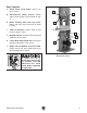
Front Controls
A. Blade Tension Scale: Allows for easy moni-
toring of blade tension in arbitrary numbers
1–8.
B. Blade Tension Handwheel: Tensions blade
in gradual increments.
C. Blade Tracking Window: Allows you to
monitor blade tracking on the wheel without
opening the wheel cover.
D. Fence and Miter Gauge: Supports workpiece
for controlled straight or angled cuts.
Figure 3. Front controls
(G0513X2BF shown).
A
C
B
D
E
E. Foot Brake (Models G0513X2BF &
G0513X2F): Quickly stops bandsaw blade
and motor.
Motor Brake
The Models G0513X2B and G0513X2BF have a
motor brake that activates and quickly stops the
blade when the OFF button is used, or the foot
pedal is pressed on the Model G0513X2BF.