MODEL G0733 18" X 47" WOOD LATHE OWNER'S Manual (For models manufactured since 10/11) Copyright © NovemBER, 2011 By Grizzly Industrial, Inc., REVISED APRIL, 2013 (ST) Warning: No portion of this manual may be reproduced in any shape Or form without the written approval of Grizzly Industrial, inc.
This manual provides critical safety instructions on the proper setup, operation, maintenance, and service of this machine/tool. Save this document, refer to it often, and use it to instruct other operators. Failure to read, understand and follow the instructions in this manual may result in fire or serious personal injury—including amputation, electrocution, or death. The owner of this machine/tool is solely responsible for its safe use.
Table of Contents INTRODUCTION................................................ 2 Manual Accuracy............................................ 2 Contact Info.................................................... 2 Machine Description....................................... 2 Identification.................................................... 3 Glossary Of Terms.......................................... 4 Machine Data Sheet....................................... 5 SECTION 1: SAFETY.................................
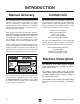
INTRODUCTION Manual Accuracy Contact Info We are proud to offer this manual with your new machine! We've made every effort to be exact with the instructions, specifications, drawings, and photographs of the machine we used when writing this manual. However, sometimes we still make an occasional mistake. We stand behind our machines. If you have any questions or need help, use the information below to contact us. Before contacting, please get the serial number and manufacture date of your machine.
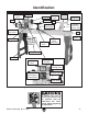
Identification Belt Tension Lever Headstock Faceplate Quill Lock Lever Tool Rest Motor Tailstock Casting Handwheel Quill Tool Rest Lock Handle Belt Tension Lock Lever Tailstock Lock Lever (reverse side) Bed Control Panel Tool Rest Base Tool Rest Base Lock Lever Stand Leg Storage Basket Stand Leg Belt Access Cover Spindle RPM Readout Spindle Indexing Holes ON/OFF Switch w/Emergency STOP Button Spindle Direction Switch Speed Control Knob Figure 1.
Glossary Of Terms The following is a list of common definitions, terms and phrases used throughout this manual as they relate to this wood lathe and turning in general. Become familiar with these terms for assembling, adjusting or operating this machine. Your safety is VERY important to us at Grizzly! Bed: The long, rail-like metal base to which the tailstock, tool base, and headstock are attached. Chuck: A mechanical device that attaches to the spindle and holds the workpiece.
Machine Data Sheet Machine Data Sheet MACHINE DATA SHEET Customer Service #: (570) 546-9663 · To Order Call: (800) 523-4777 · Fax #: (800) 438-5901 MODEL G0733 HEAVY DUTY WOOD LATHE 18" X 47" Product Dimensions: Weight.............................................................................................................................................................. 419 lbs. Width (side-to-side) x Depth (front-to-back) x Height....................................................
Spindle Information Spindle Taper............................................................................................................................................ MT#2 Spindle Thread Size.............................................................................................................................. 1-1/4 in. Spindle TPI................................................................................................................................................
SECTION 1: SAFETY For Your Own Safety, Read Instruction Manual Before Operating This Machine The purpose of safety symbols is to attract your attention to possible hazardous conditions. This manual uses a series of symbols and signal words intended to convey the level of importance of the safety messages. The progression of symbols is described below. Remember that safety messages by themselves do not eliminate danger and are not a substitute for proper accident prevention measures.
WEARING PROPER APPAREL. Do not wear clothing, apparel or jewelry that can become entangled in moving parts. Always tie back or cover long hair. Wear non-slip footwear to avoid accidentalslips,whichcouldcauselossofworkpiececontrol. hAzARdOus dusT. Dust created while using machinery may cause cancer, birth defects, or long-term respiratory damage.
Additional Safety for Wood Lathes KEEPING GUARDS IN PLACE. Make sure all guards are in place and that the lathe sits on a flat, stable surface. EYE/FACE PROTECTION. Airborne wood dust and debris can be hazardous to the eyes/face and may cause allergies or long-term respiratory health problems. Always wear eye protection or a face shield when operating the lathe. RESPIRATORY PROTECTION. Always wear a respirator when using this machine. Wood dust may cause allergies or long-term respiratory health problems.
SECTION 2: POWER SUPPLY Availability Circuit Information Before installing the machine, consider the availability and proximity of the required power supply circuit. If an existing circuit does not meet the requirements for this machine, a new circuit must be installed. To minimize the risk of electrocution, fire, or equipment damage, installation work and electrical wiring must be done by an electrican or qualified service personnel in accordance with all applicable codes and standards.
Grounding Requirements This machine MUST be grounded. In the event of certain malfunctions or breakdowns, grounding reduces the risk of electric shock by providing a path of least resistance for electric current. For 220V operation: This machine is equipped with a power cord that has an equipment-grounding wire and a grounding plug (see following figure).
SECTION 3: SETUP Needed for Setup This machine presents serious injury hazards to untrained users. Read through this entire manual to become familiar with the controls and operations before starting the machine! Wear safety glasses during the entire setup process! The G0733 and its components are very heavy. Get lifting help or use power lifting equipment such as a fork lift to move heavy items. The following are needed to complete the setup process, but are not included with your machine.
Inventory Inventory After all the parts have been removed from the shipping containers, you should have the following items: Inventory: (Figures 3–6) Qty A. Lathe Assembly —Headstock (mounted).............................. 1 —Tool Rest Base (mounted)....................... 1 —Tailstock (mounted).................................. 1 —Faceplate 6" (installed)............................ 1 B. Stand Legs.................................................. 2 C. Machine Feet.........................................
Site Considerations Weight Load Physical Environment Refer to the Machine Data Sheet for the weight of your machine. Make sure that the surface upon which the machine is placed will bear the weight of the machine, additional equipment that may be installed on the machine, and the heaviest workpiece that will be used. Additionally, consider the weight of the operator and any dynamic loading that may occur when operating the machine.
Cleanup Mounting The unpainted surfaces of your machine are coated with a heavy-duty rust preventative that prevents corrosion during shipment and storage. This rust preventative works extremely well, but it will take a little time to clean. Although not required, we recommend that you mount your new machine to the floor. Because this is an optional step and floor materials may vary, floor mounting hardware is not included.
Assembly The G0733 and its components are very heavy. Get lifting help or use power lifting equipment such as a forklift to move heavy items. 4. If bolting the lathe to the floor, skip to Step 7. Otherwise, move the tailstock, tool rest assembly, and headstock to one end of the lathe bed (refer to OPERATIONS section, beginning on Page 19, for instructions for moving these components). 5.
Power Connection 7. Place the level on the lathe bed and make necessary adjustments so that the bed is level from side-to-side and front-to-back. —If you are using the machine feet, adjust the top and bottom hex nuts on each leg to level the bed; then tighten the hex nuts to secure these adjustments. —If you are bolting your lathe to the floor, use shims under the legs to level the bed; then tighten the mounting fasteners. 8.
Test Run Once the assembly is complete, test run your machine to make sure it runs properly and is ready for regular operation. The test run consists of verifying the following: 1) The motor powers up and runs correctly and 2) the STOP button safety feature works correctly. If, during the test run, you cannot easily locate the source of an unusual noise or vibration, stop using the machine immediately, then review Troubleshooting on Page 37.
Operations SECTION 4: OPERATIONS Operation Overview To reduce the risk of serious injury when using this machine, read and understand this entire manual before beginning any operations. Damage to your eyes and lungs could result from using this machine without proper protective gear. Always wear a face shield and respirator when operating this machine.
7. Verifies the pulley ratio is set for the appropriate speed range for the operation, type of wood, and size of workpiece installed. Basic Controls 8. Verifies the spindle direction switch is in the "O" position and the spindle speed dial is turned all the way counterclockwise so the spindle does not start turning at high speed. Refer to Figure 17 and the list below to familiarize yourself with the lathe controls.
Stock Inspection & Requirements Some workpieces are not safe to turn or may require modification before they are safe to turn. Before turning a workpiece, inspect all workpieces for the following: • Workpiece Type: This machine is intended for turning natural wood products. Never attempt to turn any composite wood materials, plastics, metal, stone, or rubber workpieces; turning these materials can lead to machine damage or severe injury.
Tool Rest Adjusting Tailstock Adjusting Tool Rest The tailstock adjusts in the same manner as the headstock. The tool rest assembly on the Model G0733 has two adjustable components, to provide the safest and most stable position when operating the lathe. The tool rest base adjusts in the same manner as the headstock and tailstock. The tool rest pivots and may be adjusted vertically in the tool rest base. To position the tailstock along the length of the bed: 1.
Headstock Center Always operate the lathe with the tool rest assembly firmly locked in position. Otherwise, serious personal injury may occur by the tool being pulled from the operator's hands. 2. Make sure the mating surfaces of the center and spindle are free of debris and oily substances before inserting the center to ensure a good fit and reduce runout. 3. Insert the tapered end of the center into the spindle, and push it in with a quick, firm motion, as shown in Figure 22.
Tailstock Center Installing/Removing Tailstock Center 5. Make sure the center of the quill lock handle is aligned with the quill keyway to ensure that the tailstock center and quill will not freely rotate under load (see Figure 25). The included live center installs into the tailstock quill with an MT#2 tapered fit. Installing the Tailstock Center 1. On the tailstock, loosen the quill lock handle and rotate the handwheel until the quill extends out about 1", as shown in Figure 24.
Headstock Faceplate Installing Faceplate To install the faceplate: 1. DISCONNECT LATHE FROM POWER! 2. Insert the indexing pin into one of the indexing holes and rotate the spindle until the pin engages to prevent the spindle from turning while you tighten the faceplate, as shown in Figure 26. Changing Speed Ranges Changing Speed Ranges The Model G0733 has pulley belt configuration provided two speed ranges (see Figure 27).
Always choose the correct spindle speed for an operation. Using the wrong speed may lead to the workpiece being thrown at high speed, causing fatal or severe impact injuries. 2. Open the front belt access panel, as shown in Figure 29. 5. Reach into the belt access cavity and roll the belt onto the desired set of pulleys, as shown in Figure 31. Spindle A = High Range 330-3200 RPM B = Low Range 100-1200 RPM A B Motor Figure 31. Speed range belt positions. 6.
Spindle Turning Indexing Spindle Turning Indexing on a lathe is typically used for workpiece layout and other auxiliary operations that require equal distances around the workpiece circumference, such as clock faces or inlays. Spindle turning is the operation performed when a workpiece is mounted between the headstock and the tailstock, as shown in Figure 35.
2. Make a center mark by using a wood mallet and tapping the point of the spur center into the center of the workpiece on both ends. 3. Using a 1⁄4" drill bit, drill a 1⁄4" deep hole at the center mark on the end of the workpiece to be mounted on the headstock spur center. 4. To help embed the spur center into the workpiece, cut 1⁄8" deep saw kerfs in the headstock end of the workpiece along the diagonal lines marked in Step 1. 5.
Spindle Turning Tips: • When turning the lathe ON, stand away from the path of the spinning workpiece until the spindle reaches full speed and you can verify that the workpiece will not come loose. • Use the slowest speed when starting or stopping the lathe. Faceplate Turning Faceplate Turning Faceplate turning is when a workpiece is mounted to the faceplate, which is then mounted to the headstock spindle, as shown in Figure 39.
Mounting Workpiece to Backing Block 1. Make the backing block from a suitable size piece of scrap wood. Note: The faces of the backing block must be flat and parallel to each other, or the uneven surfaces will cause the workpiece to spin eccentricly, causing unnecessary vibration and runout. It is best to mount the backing block to the faceplate and turn the other surface flat prior to mounting. Figure 40. Typical attachment of faceplate to workpiece.
To outboard turn on the Model G0733: 1. Sanding/Finishing DISCONNECT LATHE FROM POWER! 2. Remove the tailstock and tool base from the machine by removing the hex nuts and clamp washers located underneath the assemblies, then lifting them from the lathe bed. After the turning operations are complete, the workpiece can be sanded and finished before removing it from the lathe, as shown in Figure 43. 3. Loosen the headstock, then move it all the way to the tail end of the lathe bed, as shown in Figure 42.
Selecting Turning Tools • Lathe tools come in a variety of shapes and sizes, and usually fall into five major categories. • Scrapers—Typically used where access for other tools is limited, such as hollowing operations. This is a flat, double-ground tool that comes in a variety of profiles (round nose, spear point, square nose, etc.) to match many different contours. Gouges—Mainly used for rough cutting, detail cutting, and cove profiles.
ACCESSORIES SECTION 5: ACCESSORIES Some aftermarket accessories can be installed on this machine that could cause it to function improperly, increasing the risk of serious personal injury. To minimize this risk, only install accessories recommended for this machine by Grizzly. T23311—Shop Fox 5-pc. Lathe Chisel Set With massive high speed steel blades and long ash handles, this set includes a 1" roughing gouge, 3 ⁄ 8" straight chisel, a hollowing tool, 3 ⁄ 8" spindle gouge, and a 1 ⁄ 8" parting tool.
G9274—6" Stainless Steel Outside Calipers G9275—8" Stainless Steel Outside Calipers G9276—10" Stainless Steel Outside Calipers G9277—12" Stainless Steel Outside Calipers G9278—16" Stainless Steel Outside Calipers Spring Calipers with quick adjustment nut provide fast determination of external measurements. Ideal for physically transferring dimensions from originals. Five different sizes allow you to match the best caliper for your shop needs. Figure 51. Model G9278 16" Stainless Steel Calipers.
Swan Neck G5683—Magnetic Base Light Light up your work just where you need it. This flexible neck lamp attaches with the twist of a switch so that you can use on any machine. Recommended Metal Protectants G5562—SLIPIT® 1 Qt. Gel G5563—SLIPIT® 12 oz Spray G2871—Boeshield® T-9 12 oz Spray G2870—Boeshield® T-9 4 oz Spray H3788—G96 ® Gun Treatment 12 oz Spray H3789—G96 ® Gun Treatment 4.5 oz Spray Figure 55. Magnetic base light.
SECTION 6: MAINTENANCE Lathe Bed Always disconnect power to the machine before performing maintenance. Failure to do this may result in serious personal injury. Schedule For optimum performance from your machine, follow this maintenance schedule and refer to any specific instructions given in this section. Protect the unpainted cast iron lathe bed by using a lightly oiled rag and wiping it clean after every use—this ensures moisture from wood dust does not remain on the bare metal surfaces.
SECTION 7: SERVICE Troubleshooting Review the troubleshooting and procedures in this section if a problem develops with your machine. If you need replacement parts or additional help with a procedure, call our Technical Support at (570) 546-9663. Note: Please gather the serial number and manufacture date of your machine before calling. Troubleshooting Motor & Electrical Symptom Possible Cause Machine does not 1. Emergency stop push-button is engaged/ start or a breaker faulty. trips. 2.
Wood Lathe Operation Symptom Possible Cause Corrective Action Vibration noise while machine is running; noise changes when speed is changed. 1. Belt cover loose. 1. Tighten the screws that secure the belt cover; if necessary install a soft, vibration dampening material between the belt cover and the headstock casting. Excessive vibration (with workpiece installed). 1. Workpiece mounted incorrectly. 1. Re-mount workpiece, making sure that centers are embedded in true center of workpiece. 2.
Changing V-Belt Changing Belt To change the belt: 1. DISCONNECT LATHE FROM POWER! 2. Open the front belt access panel, as shown in Figure 60. 4. Use the belt tensioning handle (Figure 61) to lift the motor assembly all the way up, then re-tighten the motor tension lock handle—this will hold the motor in place while you change the belt position. 5. Reach into the belt access cavity and roll the belt off the motor (lower) pulleys, then pull the belt off the spindle pulleys and out the side of the headstock.
SECTION 8: WIRING These pages are current at the time of printing. However, in the spirit of improvement, we may make changes to the electrical systems of future machines. Study this section carefully. If there are differences between your machine and what is shown in this section, call Technical Support at (570) 546-9663 for assistance BEFORE making any changes to the wiring on your machine. Wiring Safety Instructions SHOCK HAZARD.
wiring diagram Wiring Diagram Ground G Hot R S T L1 L2 L3 POWER INVERTER DELTA VFD-M 1.5 Kw 220V, 1/3 Phase M0 M1 M2 M3 Hot 220 VAC Single Phase 6-15 Plug (As Recommended) RPM Sensor M5 AFM +10V GND M01 M4 GND AC1 AVI MCM RPM Readout Board RB RC 080307 W2 Spindle Direction Switch KEDU ZH-A EN61058 (Both sides shown) 9 11 12 10 U2 W1 V1 U1 U1 W1 V1 GND W2 U V W Brake T1 T2 T3 B1 B2 V2 U2 RA 5 7 8 6 1 3 4 2 Speed Control Potentiometer GND Motor 2 HP 220V Model G0733 (Mfg.
Wiring Components Figure 63. Inverter box and motor box locations. Figure 60. RPM readout display board and control panel wiring. -42- READ ELECTRICAL SAFETY ON PAGE 40! Model G0733 (Mfg.
SECTION 9: PARTS Stand & Bed Parts Breakdown 9 10 11 15 12 18 17 16 19 20 21 22 24 23 13 8 25 14 7 6 3 2 26 26 32 30 31 31 27 29 29 1 4 5 Stand & Bed Parts List REF PART # DESCRIPTION REF PART # DESCRIPTION 1 2 3 4 5 6 7 8 9 10 11 12 13 14 15 16 STAND BED BED STOP HEX NUT M10-1.25 FOOT FLAT WASHER 10MM CAP SCREW M10-1.5 X 35 EXT RETAINING RING 19MM CAP SCREW M5-.
Headstock Parts Breakdown 110 112 45 113 54 111 56 58 53 57-9 57-10 57-1 42 35 34 33 93 47 99 48 92 90 60 67 62 87 89 88 68 63 64 65 57-8 41 40 36 37 39 38 43 44 97 49 61 57 100 59 55 46 66 95 70 69 57-4 57-7 57-5 71 94 86 75 74 73 81 76 57-2 83 84 85 80 103 57-6 57-3 96 104 105 101 107 106 108 -44- Model G0733 (Mfg.
Headstock Parts List REF PART # DESCRIPTION REF PART # DESCRIPTION 33 34 35 36 37 38 39 40 41 42 43 44 45 46 47 48 49 53 54 55 56 57 57-1 57-2 57-3 57-4 57-5 57-6 57-7 57-8 57-9 57-10 58 59 60 61 62 63 64 65 SPUR CENTER FACEPLATE SET SCREW M6-1 X 12 SPINDLE KEY 8 X 7 X 45 EXT RETAINING RING 30MM BALL BEARING 6206ZZ INT RETAINING RING 62MM BALL BEARING 6206ZZ HEADSTOCK CASTING RIBBED V-BELT 530J6 SPINDLE PULLEY INVERTER DELTA VFD015M21A PHLP HD SCR M5-.8 X 45 SPINDLE COVER SET SCREW M5-.
Label Placement 201 202 204 203 210 208 209 207 205 206 REF PART # DESCRIPTION REF PART # DESCRIPTION 201 202 203 204 205 BELT COVER LABEL READOUT LABEL ELECRICITY WARNING MACHINE ID LABEL GRIZZLY GREEN PAINT 206 207 208 209 210 MODEL NUMBER LABEL EYE/FACE/LUNG HAZARD LABEL READ MANUAL LABEL GRIZZLY PUTTY PAINT NOTICE LABEL P0698201 P0698202 PLABEL-14B P0733204 PPAINT-1 P0733206 PLABEL-56C PLABEL-12D PPAINT-11 P0733210 Safety labels help reduce the risk of serious injury caused by machine
WARRANTY CARD Name _____________________________________________________________________________ Street _____________________________________________________________________________ City _______________________ State _________________________ Zip _____________________ Phone # ____________________ Email _________________________________________________ Model # ____________________ Order # _______________________ Serial # __________________ The following information is given on a voluntary basis.
FOLD ALONG DOTTED LINE Place Stamp Here GRIZZLY INDUSTRIAL, INC. P.O.
WARRANTY AND RETURNS WARRANTY AND RETURNS Grizzly Industrial, Inc. warrants every product it sells for a period of 1 year to the original purchaser from the date of purchase. This warranty does not apply to defects due directly or indirectly to misuse, abuse, negligence, accidents, repairs or alterations or lack of maintenance.