
User guide

Model G0733 (Mfg. Since 10/11)
-17-
7. Place the level on the lathe bed and make
necessary adjustments so that the bed is
level from side-to-side and front-to-back.
—If you are using the machine feet, adjust
the top and bottom hex nuts on each leg to
level the bed; then tighten the hex nuts to
secure these adjustments.
—If you are bolting your lathe to the floor, use
shims under the legs to level the bed; then
tighten the mounting fasteners.
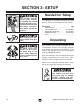
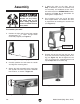
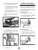
8. Insert the tool rest into the tool rest base and
tighten the tool rest lock handle, as shown in
Figure 13.
9. Attach the storage basket to the leg using
the remaining (2) M8-1.25 x 35 cap screws,
(2) 8mm lock washers, and (2) M8-1.25 hex
nuts, as shown in Figure 14.
Figure 14. Attaching basket to leg.
Leg
Basket
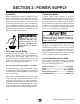
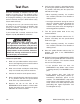
Power Connection
After you have completed all previous setup
instructions and circuit requirements, the machine
is ready to be connected to the power supply.
To avoid unexpected startups or property dam-
age, use the following steps whenever connecting
or disconnecting the machine.
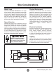
Connecting Power
Figure 15. Connecting power.
1. TurnthemachinepowerswitchOFF.
2.
Insert the power cord plug into a
matching
power supply receptacle. The machine
is
nowconnectedtothepowersource.
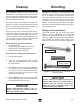
Disconnecting Power
Figure 16. Disconnecting power.
1. TurnthemachinepowerswitchOFF.
2.
Graspthemoldedplugandpullit
completely
outofthereceptacle.Donotpullbythe
cord
asthismaydamagethewiresinside.
Figure 13. Tool rest installed on the tool rest
base.
Tool Rest
Tool Rest Base
Tool Rest
Lock Handle