3 WHEEL 12" BANDSAW MODEL G8976 INSTRUCTION MANUAL COPYRIGHT © APRIL, 2003 BY GRIZZLY INDUSTRIAL, INC. WARNING: NO PORTION OF THIS MANUAL MAY BE REPRODUCED IN ANY SHAPE OR FORM WITHOUT THE WRITTEN APPROVAL OF GRIZZLY INDUSTRIAL, INC. #505203624, PRINTED IN CHINA ONLINE MANUAL DISCLAIMER THE INFORMATION IN THIS MANUAL REPRESENTS THE CONFIGURATION OF THE MACHINE AS IT IS CURRENTLY BEING SHIPPED. THE MACHINE CONFIGURATION CAN CHANGE AS PRODUCT IMPROVEMENTS ARE INCORPORATED.
WARNING Some dust created by power sanding, sawing, grinding, drilling, and other construction activities contains chemicals known to the State of California to cause cancer, birth defects or other reproductive harm. Some examples of these chemicals are: • Lead from lead-based paints. • Crystalline silica from bricks, cement, and other masonry products. • Arsenic and chromium from chemically treated lumber. Your risk from these exposures varies, depending on how often you do this type of work.
TABLE OF CONTENTS 1. 2. 3. 4. 5. 6. 7. 8. PAGE SAFETY ..............................................................................................................................................2 Safety Instructions For Power Tools ..........................................................................................2-3 Additional Safety Instructions For Bandsaws ................................................................................4 INTRODUCTION........................................
SECTION 1: SAFETY For Your Own Safety Read Instruction Manual Before Operating This Equipment The purpose of safety symbols is to attract your attention to possible hazardous conditions. This manual uses a series of symbols and signal words which are intended to convey the level of importance of the safety messages. The progression of symbols is described below. Remember that safety messages by themselves do not eliminate danger and are not a substitute for proper accident prevention measures.
Safety Instructions For Power Tools 9. USE PROPER EXTENSION CORD. Make sure your extension cord is in good condition. Conductor size should be in accordance with the chart below. The amperage rating should be listed on the motor or tool nameplate. An undersized cord will cause a drop in line voltage resulting in loss of power and overheating. Your extension cord must also contain a ground wire and plug pin. Always repair or replace extension cords if they become damaged.
Additional Safety Instructions For Bandsaws 1. DO NOT OPERATE WITH DULL OR BADLY WORN BLADES. Dull blades require more effort to use and are difficult to control. Inspect blades before each use. 2. NEVER POSITION FINGERS OR THUMBS IN LINE WITH THE CUT. Serious personal injury could occur. 3. DO NOT OPERATE THIS BANDSAW WITHOUT WHEEL, PULLEY, AND BLADE GUARDS IN PLACE. 4. WHEN REPLACING BLADES, make sure teeth face down toward the table. The force of the cut is always down.
SECTION 2: INTRODUCTION If you have any comments regarding this manual, please write to us at the address below: Lack of familiarity with this manual could cause serious personal injury. Become familiar with the contents of this manual, including all the safety warnings. Grizzly Industrial, Inc. /O Technical Documentation P.O. Box 2069 Bellingham, WA 98227-2069 C Most importantly, we stand behind our machines.
SECTION 3: CIRCUIT REQUIREMENTS 110 Volt Amperage Draw The Model G8976 motor is wired to operate at 110V and will draw the following load: Motor Load ..........................................4.5 Amps Plug Type The Model G8976 is supplied with a NEMA 5-15 plug. DO NOT modify the plug or power cord in any way. See Figure 1 for a NEMA 5-15 plug and grounded outlet. Circuit Breaker Requirements We recommend that the circuit you use your machine on should be dedicated.
Grounding Extension Cords In the event of an electrical short, grounding reduces the risk of electric shock by providing a path of least resistance to disperse electric current. This tool is equipped with a power cord that has an equipment-grounding prong. The outlet must be properly installed and grounded in accordance with all local codes and ordinances.
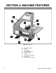
SECTION 4: MACHINE FEATURES 1 8 2 9 7 3 5 6 4 Figure 2. Front view. 1. 2. 3. 4. 5. 6. 7. 8. 9.
13 18 17 12 14 10 11 15 16 Figure 3. Internal view and back view. 10. 11. 12. 13. 14. 15. 16. 17. 18.
SECTION 5: SET UP Unpacking The machine is shipped from the manufacturer in a carefully packed cardboard box. If you discover the machine is damaged after you’ve signed for delivery, and the truck and driver are gone, you will need to file a freight claim with the carrier. Save the containers and all packing materials for possible inspection by the carrier or its agent. Without the packing materials, filing a freight claim can be difficult.
⁄ '' 58 10 # WASH Button Head Screw Flange Bolt ⁄ '' 7 16 21⁄2'' 23⁄4'' 3 WASH S WA H ASH DIA ER 8mm ASH W ASHE 6mm DI ER ASH ASHE R DIA ⁄ '' 14 D ER I ASH 21⁄4'' ⁄ '' 5 16 ET AM LINES ARE 1⁄16'' INCH APART LINES ARE 1MM APART 2 10mm R DIA ET AM 13⁄4'' 4mm MET G8976 3 Wheel 12" Bandsaw 11⁄2'' D ER IA TE ME R 16mm ⁄ '' ⁄ '' ⁄ '' ⁄ '' ⁄ '' 1'' 11⁄4'' 5 16 7 16 9 16 34 78 MET 12mm '' '' '' '' ⁄ '' 38 METE 10mm ⁄ ⁄ ⁄ ⁄ 14 38 12 58 ETER M 8mm 5mm 10mm 15mm 2
Clean Up Site Considerations The unpainted surfaces are coated with a waxy oil to protect them from corrosion during shipment. Remove this protective coating with a solvent cleaner or citrus-based degreaser such as Grizzly’s G7895 Degreaser. To clean thoroughly, some parts may need to be removed. For optimum performance from your machine, make sure you clean all moving parts or sliding contact surfaces that are coated.
Beginning Assembly This section will cover the basic assembly and adjustment instructions needed to begin operation. Complete the assembly in the order provided in this manual and then read the remaining portion of the manual before attempting any type of operation. Base Feet To attach the base feet to the bandsaw: 1. Remove the four knob bolts from the side cover (Figure 5).
Table To attach the table to the bandsaw: 1. Loosen the screw that secures the miter bar to the table (Figure 7). DO NOT remove the screw. Figure 9. Loosening the mounting screws. Keyhole Notch 5. Remove the knob bolts that secure the trunnion to the saw and set the trunnion aside (Figure 10). Figure 7. Loosening the screw that secures the miter bar to the table. 2. Slide the miter bar keyhole notch (Figure 7) off of the screw loosened in step 1. 3.
7. Slide the blade slot in the table around the blade (Figure 12) and position the table trunnion against the back of the bandsaw. ! Blade Slot Miter Gauge To assemble the miter gauge: 1. Slide the “peg” on the bottom of the miter body into the hole centered on the miter bar. 2. Secure the miter body to the miter bar with the M6-1.0 x 15 knob bolt, (Figure 14). Knob Bolt Figure 12. Attaching the table to the bandsaw. 8.
Dust Collection Bench Mounting To attach a dust collection hose: To mount the bandsaw to a workbench: Hook up a Shop Vac® or dust collection system to the 15⁄8" port located on the lower corner of the bandsaw (Figure 15). Secure the bandsaw to a workbench with 1⁄4"-20 lag bolts (Figure 16). Figure 16. Base feet mounting holes (2 of 4). Figure 15. Dust collection port.
Blade Tracking Blade Centered on Peak of Crown The blade tracking is primarily affected by the adjustment of the top wheel. To ensure operator safety, the blade tracking should be checked before the machine is operated. Blade Centered on Wheel To check and adjust the blade tracking: 1. 2. Disconnect the machine from the power source! CENTER TRACKING Adjust the upper and lower guide bearings and support bearings away from the blade.
! Start Up Serious personal injury could result if the machine is connected to the power source during assembly or adjustment. Wait until the machine is turned off, unplugged and all working parts have come to a complete stop before you attempt to assemble or adjust the machine! Figure 19. Adjusting the blade tracking. 7. Loose hair and clothing could get caught in machinery and cause serious personal injury. Keep loose clothing rolled up and long hair tied up and away from machinery.
Starting the machine: 1. Wear safety glasses at all times when running the machine! 2. Plug the machine into the power source. 3. Flip the power switch shown in Figure 20 to the ON position. Make sure your finger is poised to flip the switch to the OFF position, just in case of an emergency. The machine should run smoothly, with little or no vibration or rubbing noises. Strange or unnatural noises should be investigated and corrected before operating the machine further. Figure 20. Power switch.
6. Now, slowly increase the tension until the blade stops fluttering, then tighten the tension one more quarter of a turn. 7. Tighten the wheel lock knob bolt loosened in step 3. NOTICE All bandsaw blades will stretch. To reduce this stretching, remove the tension from the blade when not in use. NOTICE After blade tension and tracking are set correctly, properly adjust the upper and lower support bearings and guide-block assemblies into position before cutting operations.
4. Position the support bearings approximately .016" away from the back of the blade as illustrated in Figure 23. Adjusting Blade Guides 0.016" The blade guides support the sides of the blade while a cutting operation is being performed. The blade guides are designed to be adjusted in two ways—forward/backward and side-to-side. Proper adjustment of the blade guides ensures accurate cuts by eliminating back-and-forth blade flex. There is a set of blade guides both above and below the table.
3. Position the blade guides so that the edges of the bearings are just behind the blade gullets as illustrated in Figure 25. Blade Guide Bearing Trunnion Scale Pointer The table needs to be positioned 90˚ to the blade so the trunnion scale pointer can be correctly set. To adjust the trunnion scale pointer: Blade Gullet Figure 25. Correct blade guide position. 4. 5. Tighten the hex nut that was loosened in step 2 to secure the position of the blade guides. 1.
4. Raise the upper blade guide assembly and place a 6" machinist’s square or try-square on the table next to the side of the blade as illustrated in Figure 27. Figure 27. Squaring table to blade. 5. Adjust the table until it is 90˚ to the blade. 6. Tighten the knob bolts loosened in step 3. 7. Adjust the trunnion scale pointer to the 0˚ mark as shown in Figure 26.
SECTION 6: OPERATIONS Operation Safety Guide Post Your safety is important! Please follow the warnings below during this entire section: The guide post moves the upper blade guide assembly up and down. The guide post/upper blade guide assembly is set correctly when the bottom edge of the guide bearings are approximately 1⁄4" above the top surface of the workpiece being cut. To avoid serious personal injury, read and become familiar with the entire instruction manual before using the Model G8976.
Table Tilt Ripping To adjust the table tilt: 1. Disconnect the machine from the power source! 2. Loosen the two knob bolts that secure the table trunnion to the side of the bandsaw. 3. Use the trunnion scale to adjust the table to the desired angle (Figure 29). 4. Tighten the knob bolts loosened in step 2. Trunnion Scale Ripping is cutting with the grain direction of the workpiece. Ripping man-made wood products (like plywood) is cutting parallel to the longest side. To perform a rip cut: 1.
Crosscutting Resawing Crosscutting is cutting against the grain direction of the workpiece. Crosscutting man-made wood products (like plywood) is cutting parallel to the shortest side. Resawing (Figure 32) is cutting a board into thinner pieces. The maximum cutting height is 37⁄8". To perform a resaw cut: To perform a 90˚ crosscut: 1. Install the widest blade available for your bandsaw when performing resaw operations. The cut will be straighter and more accurate.
Blade Lead Knob Bolt It is common for a bandsaw blade to wander off the cut line when sawing (Figure 33). This is called “blade lead.” To correct blade lead: 1. Verify that the miter slot and fence are parallel to the side of the blade. 2. Make sure the blade is tracking properly and that it is correctly tensioned. 3. If the blade tension and tracking are correctly adjusted, and it is not convenient to replace the blade, compensate for lead by skewing the fence. Figure 33.
Cutting Curves Stacked Cuts NOTICE Before making stacked cuts, make sure both the table and the blade are square to one another. If the table and blade are not square to one another, the cut-out workpieces will not be the same size. Refer to Figure 36 on page 29 to determine the best blade for cutting various curves. When cutting curves, simultaneously feed and turn the stock carefully so that the blade follows the layout line without being twisted.
Blade Speed Blade Selection The Model G8976 blade speed is variable and can be adjusted from 50 to 2300 FPM. Blade speed adjustments are made by turning the blade speed knob below the power switch (Figure 35). NOTICE Cutting with the bandsaw without correctly adjusting the tracking and tension may result in the blade falling off the wheels, causing damage to the machine. Read and follow the directions in Section 5: Set Up after changing or adjusting the saw blade.
TOOTH STYLE Tooth shape, gullet size, and cut angle are all factors that determine the tooth style. Figure 37 illustrates the three main categories of tooth style. TOOTH PITCH Usually measured as TPI, tooth pitch refers to the number of teeth-per-inch. More teeth-per-inch (fine pitch) will cut slower, but will produce a smoother cut; while fewer teeth-per-inch (coarse pitch) will cut faster, but will produce a rougher cut.
BLADE BREAKAGE Many factors can cause a blade to break. Breakage is often unavoidable because of the high levels of stress and strain applied to the blade. Avoidable breakage is usually the result of improper care or judgement on the part of the operator when mounting or adjusting the blade or support guides. BLADE CARE When taken care of correctly, bandsaw blades will provide a long usable life.
SECTION 7: MAINTENANCE Maintenance Safety Schedule Your safety is important! Please follow the warnings below during this entire section: Check the following items before you use the bandsaw: • Loose mounting bolts. ! Serious personal injury could occur if you connect your machine to the power source during the maintenance process. DO NOT connect the machine to the power source while performing any maintenance on this machine. • Worn or damaged blade. • Worn or damaged wires.
Maintenance Log Date Approximate Hours Of Use G8976 3 Wheel 12" Bandsaw Maintenance Performed -33-
Blade Changes To change the blade: 1. Unplug the machine from the power source! 2. Remove the front cover. 3. Remove the screw that is located in the table blade slot. 4. Loosen the tension on the blade. 5. Wearing leather gloves, slowly spin the blade while pulling it off of the wheels. 6. Carefully slide the blade through the blade slot in the table. 7. Store the blade in a safe place. 8. Reverse the above steps when installing a blade.
SECTION 8: REFERENCE INFO General This section contains the following subsections for the Model G8976: aftermarket accessories, data sheets, wiring diagrams, parts diagrams and list, troubleshooting, and warranty/return information. If you need parts or help in assembling your machine, or if you need operational information, call the service department at (570) 546-9663. Trained service technicians will be glad to help you.
MACHINE DATA SHEET Customer Service #: (570) 546-9663 • To Order Call: (800) 523-4777 • Fax #: (800) 438-5901 MODEL G8976 3 WHEEL 12" BANDSAW design Type .................................................................................................... Bench Model Overall Dimensions: Table ..........................................................................................................131⁄2" x 31⁄2" Overall Height ..................................................................................
Parts Diagrams & Lists G8976 3 Wheel 12" Bandsaw -37-
REF 2 2A 3 7 11 12 13 15 16 17 18 21 22 23 24 25 28 31 33 34 35 36 38 39 40 41 43 44 45 46 47 48 50 51 53 54 56 57 58 59 60 61 62 63 67 68 69 70 71 -38- PART # P8976002 P8976002 PN03M P8976007 P8976011 P8976012 PS14M P8976015 P8976016 P8976017 PSB29M P8976021 P8976022 P8976023 P8976024 P8976025 P8976028 P8976031 P8976033 P8976034 P8976035 PW03M PFH17M PW05M PS17M P8976041 P8976043 P8976044 PFH12M PHTEK1M P8976047 PS08M P8976050 PN03M PB07M P8976054 P8976056 P8976057 PS02M P8976059 P8976060 PS05M P8976062
Troubleshooting Motor will not start. 1. Low voltage. 2. Open circuit in motor or loose connections. 1. Check power line for proper voltage. 2. Inspect all lead connections on motor for loose or open connections. Motor will not start; fuses or circuit breakers blow. 1. Short circuit in line cord or plug. 1. Inspect cord or plug for damaged insulation and shorted wires. 2. Inspect all connections on motor for loose or shorted terminals or worn insulation. 3. Reduce load on circuit. 2.
Warranty & Returns Grizzly Industrial, Inc. warrants every product it sells for a period of 1 year to the original purchaser from the date of purchase. This warranty does not apply to defects due directly or indirectly to misuse, abuse, negligence, accidents, repairs or alterations or lack of maintenance.
WARRANTY CARD Name ____________________________________________________________________________________ Street ____________________________________________________________________________________ City ______________________________________________________________State________Zip_________ Phone Number_______________________E-Mail_______________________FAX________________________ MODEL #_____________________Serial # __________________________ Order #______________________ The following information is given on
FOLD ALONG DOTTED LINE Place Stamp Here GRIZZLY INDUSTRIAL, INC. P.O.
Buy Direct and Save with Grizzly ® – Trusted, Proven and a Great Value! ~Since 1983~ Visit Our Website Today For Current Specials! ORDER 24 HOURS A DAY! 1-800-523-4777