MODEL G0755 HEAVY-DUTY MILL/DRILL w/STAND & POWER FEED OWNER'S Manual (For models manufactured since 1/13) Copyright © APRIL, 2013 By Grizzly Industrial, Inc., REVISED JANUARY, 2014 (TS) Warning: No portion of this manual may be reproduced in any shape Or form without the written approval of Grizzly Industrial, inc. #TS15627 printed IN CHINA V1.01.
This manual provides critical safety instructions on the proper setup, operation, maintenance, and service of this machine/tool. Save this document, refer to it often, and use it to instruct other operators. Failure to read, understand and follow the instructions in this manual may result in fire or serious personal injury—including amputation, electrocution, or death. The owner of this machine/tool is solely responsible for its safe use.
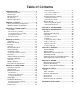
Table of Contents INTRODUCTION................................................ 2 Machine Description....................................... 2 Contact Info.................................................... 2 Manual Accuracy............................................ 2 Identification.................................................... 3 Machine Data Sheet....................................... 4 SECTION 1: SAFETY........................................ 6 Safety Instructions for Machinery...................
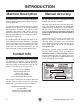
INTRODUCTION Machine Description Manual Accuracy The Model G0755 is a free-standing mill/drill that strikes a great balance between being heavy-duty and high-precision. We are proud to provide a high-quality owner’s manual with your new machine! The spindle is equipped with precision P5 spindle bearings and is driven by an oil-bath-lubricated and gear-driven headstock. The spindle is fully reversible and features both coarse and fine downfeed controls.
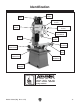
Identification Z-Axis Motor Spindle Motor Spindle Speed Levers Control Panel Z-Axis Crank Coarse Downfeed Levers Fine Downfeed Handwheel Quill & Spindle X-Axis Handwheel X-Axis Power Feed Work Table Stand w/Splash Pan Y-Axis Handwheel Mounting Location To reduce your risk of serious injury, read this entire manual bEFORE using machine. Model G0755 (Mfg.
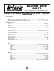
Machine Data Sheet MACHINE DATA SHEET Customer Service #: (570) 546-9663 · To Order Call: (800) 523-4777 · Fax #: (800) 438-5901 MODEL G0755 HEAVY-DUTY MILL/DRILL WITH STAND AND POWER FEED Product Dimensions: Weight.............................................................................................................................................................. 992 lbs. Width (side-to-side) x Depth (front-to-back) x Height........................................................
Main Specifications: Operation Info Spindle Travel.............................................................................................................................................. 5 in. Max Distance Spindle to Column............................................................................................................... 10 in. Max Distance Spindle to Table.................................................................................................................. 18 in.
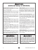
SECTION 1: SAFETY For Your Own Safety, Read Instruction Manual before Operating This Machine The purpose of safety symbols is to attract your attention to possible hazardous conditions. This manual uses a series of symbols and signal words intended to convey the level of importance of the safety messages. The progression of symbols is described below. Remember that safety messages by themselves do not eliminate danger and are not a substitute for proper accident prevention measures.
WEARING PROPER APPAREL. do not wear clothing, apparel or jewelry that can become entangled in moving parts. Always tie back or cover long hair. Wear non-slip footwear to avoid accidental slips, which could cause loss of workpiece control. HAzARDOUS DUST. dust created while using machinery may cause cancer, birth defects, or long-term respiratory damage. Be aware of dust hazards associated with each workpiece material, and always wear a niosh-approved respirator to reduce your risk. HEARING PROTEcTION.
Additional Safety for Mill/Drills UNDERSTANDING CONTROLS. Make sure you understand the use and operation of all controls before starting the mill/drill. SAFETY ACCESSORIES. To reduce the risk of injury from flying chips, always use a face shield in addition to safety glasses when using the mill/drill. CLEAN-UP. Metal chips can cut your hands. DO NOT clear chips by hand or compressed air that can force the chips farther into the machine.
SECTION 2: POWER SUPPLY Availability Circuit Requirements for 220V Before installing the machine, consider the availability and proximity of the required power supply circuit. If an existing circuit does not meet the requirements for this machine, a new circuit must be installed. To minimize the risk of electrocution, fire, or equipment damage, installation work and electrical wiring must be done by an electrican or qualified service personnel in accordance with all applicable codes and standards.
Grounding Instructions This machine MUST be grounded. In the event of certain malfunctions or breakdowns, grounding reduces the risk of electric shock by providing a path of least resistance for electric current. The power cord and plug specified under “Circuit Requirements for 220V” on the previous page has an equipment-grounding wire and a grounding prong.
SECTION 3: SETUP Unpacking Inventory Your machine was carefully packaged for safe transportation. Remove the packaging materials from around your machine and inspect it. If you discover any damage, please call us immediately at (570) 546-9663 for advice. The following is a list of items shipped with your machine. Before beginning setup, lay these items out and inventory them. Save the containers and all packing materials for possible inspection by the carrier or its agent.
Cleanup the unpainted surfaces of your machine are coated with a heavy-duty rust preventative that prevents corrosion during shipment and storage. this rust preventative works extremely well, but it will take a little time to clean. Be patient and do a thorough job cleaning your machine. the time you spend doing this now will give you a better appreciation for the proper care of your machine's unpainted surfaces.
Site Considerations Weight Load Physical Environment refer to the Machine Data Sheet for the weight of your machine. Make sure that the surface upon which the machine is placed will bear the weight of the machine, additional equipment that may be installed on the machine, and the heaviest workpiece that will be used. Additionally, consider the weight of the operator and any dynamic loading that may occur when operating the machine.
Lifting & Placing 4. Insert steel rods into holes in stand, as shown in Figure 5. HEAVY LIFT! Straining or crushing injury may occur from improperly lifting machine or some of its parts. To reduce this risk, get help from other people and use a fork lift (or other lifting equipment) rated for weight of this machine. Power lifting equipment, steel rods (refer to Page 11), and at least two other people are required to lift and place the mill. Steel Rods Figure 5. LIfting setup.
Anchoring to Floor Assembly Anchoring machinery to the floor prevents tipping or shifting and reduces vibration that may occur during operation, resulting in a machine that runs slightly quieter and feels more solid. Except for the handwheel handles, the mill/drill was fully assembled at the factory. if the machine will be installed in a commercial or workplace setting, or if it is permanently connected (hardwired) to the power supply, local codes may require that it be anchored to the floor.
Joining Drill Chuck & Arbor Lubricating Mill/Drill An arbor is included for the drill chuck that comes with this machine. The following procedure describes how to install the arbor in the chuck. GEARBOX MUST BE FILLED WITH OIL! After the arbor is installed in the drill chuck, it is very difficult to separate the assembly. If you would like to use a different chuck in the future, we recommend obtaining a new arbor.
Test Run 4. Twist Emergency Stop button clockwise until it pops out—this resets the switch so the machine can be started (see Figure 10). The purpose of the test run is to verify that the machine functions properly and is ready for regular operation. Before beginning this procedure, make sure: (1) you understand the safety instructions at the beginning of this manual, (2) the machine is set up properly, and (3) all tools and objects used during setup are cleared away from the machine.
Spindle Break-In Before placing operationql loads on the spindle, complete this break-in procedure to fully distribute lubrication throughout the bearings and ensure trouble-free performance. Failure to complete the spindle break-in process may lead to premature failure of the bearings—this will not be covered under warranty. To perform the spindle break-in procedure: 1. Make sure the spindle is completely stopped, then set spindle speed to 90 RPM (refer to Page 26 for detailed instructions).
SECTION 4: OPERATIONS Operation Overview The purpose of this overview is to provide the novice machine operator with a basic understanding of how the machine is used during operation, so the machine controls/components discussed later in this manual are easier to understand. Due to the generic nature of this overview, it is not intended to be an instructional guide.
Control Panel Downfeed Controls Refer to Figure 11 and the following descriptions to become familiar with the control panel functions. Identification F A A B B F C E C D E Figure 12. Downfeed controls. D A. Fine Downfeed Handwheel Figure 11. Control panel components. B. Depth Pointer and Scale A. Power/ON Lamp Button: Lights when machine is connected to power. Push this button to enable power to the motor. C. Quill Lock Lever B.
Depth Stop The depth stop limits the downward movement of the cutting tool. With the use of the depth pointer adjustment knob (see D in Figure 12), it can be adjusted anywhere within 0"–5". This is useful when performing repeat operations. The Z-axis crank will rotate rapidly and may cause impact injuries if left attached during powered Z-axis operation. Always remove Z-axis crank before using the switch on the control panel.
Tilting Headstock 1. Use a 22mm wrench to loosen the three locking hex nuts (see Figures 17–18), then tilt headstock to desired angle on tilt scale. Tilt Scale Table Travel The table travels in two directions, as illustrated in Figure 19. These movements are controlled by handwheels and the X-axis power feed. When using the power feed, travel is limited by the position of the limit stops along the front of the table.
X- & Y-Axis Handwheels X-Axis Power Feed Use Figure 21 and the following descriptions to become familiar with the X- and Y-axis manual table movement. Use Figures 22–23 and the following descriptions to become familiar with the power feed controls. A B B D F A C C E D Figure 22. X-axis power feed controls. Figure 21. Table locks and limit stops. G A. Y-Axis Handwheel: Moves table back and forth. B.
Installing/Removing Tooling Installing Tool Holder Tool Needed Qty Wrench 19mm.................................................... 1 To install tool holder: The Model G0755 includes the following spindle tools (see Figure 24): A. B16 Drill Chuck w/R-8 Arbor: Use with drill bits. 1. DISCONNECT MACHINE FROM POWER! 2. Remove drawbar cap as shown in Figure 25. B. R-8–MT#3 Spindle Sleeve: Use with MT#3 tooling with or without a tang. Has a drift key slot for tool removal. Drawbar C.
Removing Tool Holder Tools Needed Qty Wrench 19mm.................................................... 1 Brass or Dead Blow Hammer............................. 1 To remove tool holder: 1. DISCONNECT MACHINE FROM POWER! 2. Remove drawbar cap, and only unthread drawbar from tool holder one full rotation. Note: Do not fully unthread tool holder from drawbar, or drawbar and tool holder threads could be damaged during the next step. 3. Tap top of drawbar with hammer to unseat taper. 4.
Setting Spindle Speed The chart below explains how to position the spindle range and speed levers to set the desired spindle speed. Spindle Speed Range Lever Speed Lever 90 RPM L 1 210 RPM L 2 345 RPM L 3 670 RPM H 1 1180 RPM H 2 1970 RPM H 3 Change spindle speed ONLY when the spindle is completely stopped. Otherwise, machine damage could occur. With the spindle completely stopped, position the spindle range and speed levers (see Figure 27) to set the spindle speed.
ACCESSORIES SECTION 5: ACCESSORIES Installing unapproved accessories may cause machine to malfunction, resulting in serious personal injury or machine damage. To reduce this risk, only install accessories recommended for this machine by Grizzly. NOTICE Refer to our website or latest catalog for additional recommended accessories. T23962—ISO 68 Moly-D Way Oil, 5 gal. T23963—ISO 32 Moly-D Machine Oil, 5 gal.
H7527—6" Rotary Table Set Use this 6" Rotary Table in either the horizontal or vertical position for a variety of milling applications and with the set of dividing plates and adjustable tailstock, your milling applications are nearly unlimited. With 4° table movement per handle rotation and 20 second vernier scale, control is very accurate and precise. Also includes a 3 ⁄ 8" clamping set for the 4-slot table. Everything you need in one great set! Figure 32. H7527 6" Rotary Table Set.
G9760—20-PC. 2 & 4 Flute TiN End Mill Set. Includes these sizes and styles in two and four flute styles: 3/16", 1/4", 5/16", 3/8", 7/16", 1/2", 9/16", 5/8", 3/8", 11 /16", and 3/4". Figure 36. G9760 20-PC End Mill Set. G5774—R-8 End Mill Holder Set Hold various sized end mills in your R-8 spindle with this End Mill Holder Set. Includes holders for 3 ⁄ 16", 3 ⁄ 8", 1⁄ 2", 5 ⁄ 8" and 3 ⁄4" end mills. G5641—1-2-3 Blocks G9815—Parallel Set Blocks are square to within .0003". Measure 1" x 2" x 3".
SECTION 6: MAINTENANCE To reduce risk of shock or accidental startup, always disconnect machine from power before adjustments, maintenance, or service. Schedule For optimum performance from your machine, follow this maintenance schedule and refer to any specific instructions given in this section. Daily Check: Loose mounting bolts. • • Damaged tooling. • Worn or damaged wires. • Clean debris and built up grime off of machine. • Any other unsafe condition.
Headstock Reservoir Oil Type.......Model T23962 or ISO 68 Equivalent Oil Amount................................................. 3 1⁄4 Qt. Check/Add Frequency............8 Hrs. of Operation Change Frequency................................. Annually 4. Place a 1-gallon or larger drain pan on the table under the headstock. 5. Remove the drain plug (see Figure 44) from underneath the headstock. Allow the oil to completely drain into the pan.
Ball Oilers Table/Column Ways & Quill Oil Type.......Model T23963 or ISO 32 Equivalent Oil Amount.......................................... 1–2 Pumps Lubrication Frequency............8 Hrs. of Operation Oil Type.......Model T23962 or ISO 68 Equivalent Oil Amount.............................................Thin Coat Lubrication Frequency............8 Hrs.
Table Leadscrews Quill Rack & Pinion Oil Type.......Model T23962 or ISO 68 Equivalent Oil Amount.............................................Thin Coat Lubrication Frequency..........40 Hrs. of Operation Oil Type................. NLGI#2 Grease or Equivalent Oil Amount.............................................Thin Coat Lubrication Frequency........
Z-Axis Leadscrew Oil Type................. NLGI#2 Grease or Equivalent Oil Amount.............................................Thin Coat Lubrication Frequency........ 90 Days of Operation Using a 5mm hex wrench, remove the rear column cover to access the Z-axis leadscrew and worm gear (see Figure 52). Use mineral spirits, shop rags, and a brush to clean away the old grease from the leadscrew threads and the worm gear teeth.
SECTION 7: SERVICE Review the troubleshooting and procedures in this section if a problem develops with your machine. If you need replacement parts or additional help with a procedure, call our Technical Support at (570) 546-9663. Note: Please gather the serial number and manufacture date of your machine before calling. Troubleshooting Symptom Possible Cause Possible Solution Machine does not start. 1. Emergency stop button depressed. 1.
Symptom Possible Cause Possible Solution Tool loose in spindle. 1. Tool is not fully drawn up into spindle taper. 2. Debris on tool or in spindle taper. 3. Taking too big of a cut. 1. Tighten draw bar. 1. Spindle speed/feed rate is too fast. 1. Set spindle speed correctly (Page 25) or use slower feed rate. 2. Use larger cutting tool and slower feed rate. 3. Use coolant fluid or oil for appropriate application. 4. Decrease depth of cut. 5. Fully retract spindle and lower headstock.
Adjusting Gibs Gibs are tapered lengths of metal that are sandwiched between two moving surfaces. Gibs control the gap between these surfaces and how they slide past one another. Correctly adjusting the gibs is critical to producing good results. Correctly positioning gibs is a matter of trial and error and patience. Tight gibs make table movement more accurate but stiff. Loose gibs make table movement sloppy but easier to do.
Tramming Spindle When your operation requires that the spindle axis be precisely perpendicular to the table, you must tram the spindle with the table. Simply adjusting the headstock tilt to the 90° mark on the tilt scale will not be precise enough for highly accurate results. This procedure involves mounting a dial indicator to the quill or spindle, rotating it around the table, and adjusting the head position so that the spindle axis is 90° to the table X-axis, as illustrated in Figure 55.
5. Place the parallel block directly under spindle and indicator across length of table, as illustrated in Figure 57. Note: If you must re-position quill to accommodate the above step, then review tasks in Step 2 to make sure mill is properly prepared for tramming. Table (Top View) Parallel Block Replacing Power Feed Carbon Brushes The X-axis power feed motor has a carbon brushes that will wear with normal use. There is one on the top of the power feed (see Figure 58) and one on the bottom.
Tightening Return Spring Tension The return spring moves the spindle back up when the coarse downfeed handles are released. The tension of this spring was adjusted at the factory, but it may need to be tightened during the life of the mill/drill. Important: Do not perform this procedure unless it is absolutely necessary.
machine SECTION 8: WIRING These pages are current at the time of printing. However, in the spirit of improvement, we may make changes to the electrical systems of future machines. Compare the manufacture date of your machine to the one stated in this manual, and study this section carefully. If there are differences between your machine and what is shown in this section, call Technical Support at (570) 546-9663 for assistance BEFORE making any changes to the wiring on your machine.
Con Pan Electrical Box Wiring Control Panel Ground 12 Component Legend: Power Lamp * 3 X2 Spindle Forward § 11 4 4 11 5 2 1 NC 2 4 NO 3 3 NO 4 Z-Axis Switch § 3 NO 4 Spindle Stop ‡ 4 11 4 1 NC 2 4 PE 0 X1 3 NO 4 * = PNC EB2 § = Minger LA125H-BE101C ‡ = Minger LA125H-BE102C Spindle Reverse § Emegency Stop ‡ Electrical Box 3 8 3 N L 1L1 3L2 5L 13NO 21NC 14 15 L A1 3L2 1L1 5L3 A1 7 5L3 1L1 L L 3L2 13 A1 5L3 11 43NC 10 13NO 21NC 31NC 43NC 13NO 21NC
Motors & Other Electrical Wiring 220V Spindle Motor To Electrical Box (Page 42) 220V NEMA 6-15 (As Recommended) Ground PE V2 V1 U1 U2 Ground G Hot Run Capacitor 20MFD 450VAC Hot U1 W2 Start Capacitor 150MFD 250VAC V1 U2 W1 V2 To Electrical Box (Page 42) Upper Z-Axis Limit Switch 5 220V Z-Axis Motor 6 Lower Z-Axis Limit Switch 6 5 8 9 To Electrical Box (Page 42) Model G0755 (Mfg.
Electrical Photos Electrical Box Transformer Contactors Capacitor Z-Axis Motor -44- READ ELECTRICAL SAFETY ON PAGE 41! Z-Axis Limit Switch Model G0755 (Mfg.
Electrical Photos Control Panel (Rear View) Z-Axis Switch Power Lamp Spindle Forward Spindle Reverse Spindle Stop Emergency Stop Spindle Motor Model G0755 (Mfg.
SECTION 9: PARTS Head 7 24 8 122 11 124 12 36 24 59 123 73 49 48 29 47 46 58 45 121 57 108 105 98 97 86 100 87 24 107 106 111 112 113 114 109 115 113 21 110 20 114 117 118 10 20 112 116 65 115 21 66 70 13 4 38 33 32 43 36 68 40 7-9 30 27 28 35 83 77 79 53 28 90 82 101 28 103 92 91 78 80 81 119 84 88 93 55 71 64 7-6 26 39 1 22 96 94 7-5 7-7 29 99 56 69 7-3 7-4 7-8 25 67 7-2 2 42 34 101 85 7-1 18 41 31 37 50 36 23 5 3 4 3 39 36 44 6 19
Head Parts List REF PART # DESCRIPTION REF PART # DESCRIPTION 1 2 3 4 5 6 7 7-1 7-2 7-3 7-4 7-5 7-6 7-7 7-8 7-9 8 9 10 11 12 13 14 18 19 20 21 22 23 24 25 26 27 28 29 30 31 32 33 34 35 36 37 38 39 40 41 42 43 44 45 46 47 HEADSTOCK HOUSING HEADSTOCK TOP COVER INT RETAINING RING 62MM INT RETAINING RING 35MM FLANGED END CAP QUILL SEAL MOTOR 2HP 220V 1-PH MOTOR FAN COVER MOTOR FAN MOTOR JUNCTION BOX S CAPACITOR 150M 250V 1-5/8 X 3 R CAPACITOR 20M 450V 1-1/2 X 3-1/4 CENTRIFUGAL SWITCH 25-1725 CONTACT PLATE
Head Parts List REF PART # DESCRIPTION REF PART # DESCRIPTION 106 107 108 109 110 111 112 113 114 INNER LOCK PLUNGER OUTER LOCK PLUNGER ADJUSTABLE HANDLE SPEED RANGE SHIFT SHAFT SPEED RANGE SHIFT ROCKER ARM SPEED RANGE SHIFT FORK EXT RETAINING RING 12MM CAP SCREW M6-1 X 14 SHIFT ROD 115 116 117 118 119 121 122 123 124 SHAFT SEAL SPEED SHIFT SHAFT SPEED SHIFT FORK SPEED SHIFT ROCKER ARM COMPRESSION SPRING DRAWBAR ASSEMBLY 7/16-20 X 17-3/4 ELECTRICAL CABINET ELECTRICAL CABINET FRONT COVER ELECTRICAL CA
Table & Column 315-1 315-3 315-2 285 262 269 219 231 265 257 228 230 254 206 261 204 205 263 214 264 320322 215 321 221 242 249 240 327 330 329 326 325 218 328 225 227 223 226 241 221 237 324 245 222 252 238 220 219 209 293 294 207 210 212 Model G0755 (Mfg.
Table & Column Parts List REF PART # DESCRIPTION REF PART # DESCRIPTION 201 202 203 204 205 206 207 208 209 210 211 212 213 214 215 218 219 220 221 222 223 224 225 226 227 228 230 231 235 236 237 238 239 240 241 242 244 245 246 248 249 252 254 255 256 257 258 259 BASE COLUMN Y-AXIS LEADSCREW BRACKET HEAD MOUNT Z-AXIS GIB GIB ADJUSTMENT SCREW THRUST BEARING 51103 Y-AXIS LEADSCREW DIAL CLUTCH TABLE GRADUATED DIAL TABLE HANDWHEEL HANDWHEEL HANDLE SHOULDER SCREW M8-1.
Electrical Components 401 406 402 405 403 404 415 407 407 407 410 409 414 411 408 407 412 413 REF PART # DESCRIPTION REF PART # DESCRIPTION 401 402 403 404 405 406 407 408 CAPACITOR 7M 500V 20 X 32 X 48MM GROUNDING PLATE FUSE HOLDER FUSE 2A 250V 5 X 25MM TERMINAL BAR 1-PC TRANSFORMER AOHENGDA ELEC JBK63VA 24-400V CONTACTOR SIEMENS 3TB41 29V SPINDLE STOP BUTTON MINGER LA125HBE101C 409 410 411 412 413 414 415 SPINDLE REV BUTTON MINGER LA125HBE102C Z-AXIS SWITCH MINGER LA125HBE102C E-STO
Power Feed 501-1 501 501-2 501-4 501-3 501-5 501-6 REF PART # DESCRIPTION REF PART # DESCRIPTION 501 501-1 501-2 501-3 POWER FEED ASSY ALIGN AS-235 MOUNTING BRACKET 2-PC CONTROL HANDLE SPEED CONTROL KNOB 501-4 PT24824004 501-5 PT24824008 501-6 P0755501-6 ON/OFF SWITCH ZYTEL GEAR ASSEMBLY POWER FEED MOTOR CARBON BRUSH -52- T24824 PT24824001A PT24824002 PT24824003 Model G0755 (Mfg.
Accessories 504 505 506 512 507 511 519 510 518 509 514 513 508 515 516 520 517 REF PART # DESCRIPTION REF PART # DESCRIPTION 504 505 506 507 508 509 510 511 512 TOOLBOX T-BOLT M12-1.75 X 55 FLAT WASHER 12MM HEX NUT M12-1.
Machine Labels & Cosmetics 606 601 605 602 604 603 REF PART # DESCRIPTION REF PART # DESCRIPTION 601 602 603 HEADSTOCK LABEL MODEL NUMBER LABEL MACHINE ID LABEL 604 605 606 GRIZZLY GREEN TOUCH-UP PAINT CONTROL PANEL LABEL ELECTRICITY LABEL P0755601 P0755602 P0755603 PPAINT-01 P0755605 PLABEL-14A Safety labels help reduce the risk of serious injury caused by machine hazards.
WARRANTY CARD Name _____________________________________________________________________________ Street _____________________________________________________________________________ City _______________________ State _________________________ Zip _____________________ Phone # ____________________ Email _________________________________________________ Model # ____________________ Order # _______________________ Serial # __________________ The following information is given on a voluntary basis.
FOLD ALONG DOTTED LINE Place Stamp Here GRIZZLY INDUSTRIAL, INC. P.O.
WARRANTY & RETURNS Grizzly Industrial, Inc. warrants every product it sells for a period of 1 year to the original purchaser from the date of purchase. This warranty does not apply to defects due directly or indirectly to misuse, abuse, negligence, accidents, repairs or alterations or lack of maintenance.