DRILL PRESS MODEL G4008/G4009 INSTRUCTION MANUAL COPYRIGHT © 1996 BY GRIZZLY IMPORTS, INC. WARNING: NO PORTION OF THIS MANUAL MAY BE REPRODUCED IN ANY SHAPE OR FORM WITHOUT THE WRITTEN APPROVAL OF GRIZZLY IMPORTS, INC. APRIL, 1997 PRINTED IN USA DISCONTINUED MACHINE MANUAL DISCLAIMER THE INFORMATION IN THIS MANUAL REPRESENTS THE LAST CONFIGURATION OF THE MACHINE BEFORE IT WAS DISCONTINUED. MACHINE CONFIGURATIONS MAY HAVE CHANGED AS PRODUCT IMPROVEMENTS WERE INCORPORATED.
WARNING Some dust created by power sanding, sawing, grinding, drilling, and other construction activities contains chemicals known to the State of California to cause cancer, birth defects or other reproductive harm. Some examples of these chemicals are: • Lead from lead-based paints. • Crystalline silica from bricks, cement, and other masonry products. • Arsenic and chromium from chemically treated lumber. Your risk from these exposures varies, depending on how often you do this type of work.
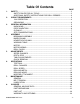
Table Of Contents 1. 2. 3. 4. 5. 6. 7. 8. PAGE SAFETY ....................................................................................................................2 SAFETY RULES FOR ALL TOOLS ....................................................................2 ADDITIONAL SAFETY INSTRUCTIONS FOR DRILL PRESSES ......................3 CIRCUIT REQUIREMENTS...................................................................................... 4 110V OPERATION ......................................
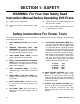
SECTION 1: SAFETY WARNING: For Your Own Safety Read Instruction Manual Before Operating Drill Press a) Always wear eye protection. c) Clamp workpiece or brace against the column to prevent rotation. b) Do not wear gloves, necktie or loose clothing. d) Use recommended speed for drill accessory and workpiece material. Safety Instructions For Power Tools These safety rules cannot cover every situation in a work shop. Consider your conditions when setting up or operating your drill press 1.
12. SECURE WORK. Use clamps or a vise to hold work when practical. It’s safer than using your hand and frees both hands to operate tool. 17. USE RECOMMENDED ACCESSORIES. Consult the owner’s manual for recommended accessories. The use of improper accessories may cause risk of injury to persons. 13. DON’T OVERREACH. Keep proper footing and balance at all times. 18. CHECK DAMAGED PARTS.
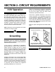
SECTION 2: CIRCUIT REQUIREMENTS 110V Operation The G4008/G4009 Drill Press is supplied with a U.S made 110V/220V motor. Under normal use, the motor draws approximately 9 amps @ 110V. We recommend using a 15 amp circuit breaker or a 15 amp slow blow fuse for 110V operation. This should be satisfactory for normal use, while preventing motor damage from high heat caused by overload.
SECTION 3: GENERAL INFORMATION Grizzly Imports, Inc. is proud to offer the Model G4008/G4009 Drill Press. This drill press is a part of Grizzly’s growing family of fine woodworking and metalworking machinery. When used according to the guidelines stated in this manual, you can expect years of trouble-free, enjoyable operation. The Model G4008/G4009 is intended for home and medium-duty professional use. This drill press features a 1,725 R.P.M., 1⁄2 H.P.
Unpacking Piece Inventory The Model G4008/G4009 Drill press is shipped from the manufacturer in a carefully packed carton. If you discover the machine is damaged after you’ve signed for delivery, please call Customer Service immediately for advice.
Clean up The column and other unpainted parts of the Model G4008/G4009 are coated with a waxy oil that protects them from corrosion during shipment. Remove the protective coating with mineral spirits and paper towels. Do not use gasoline or other petroleum based solvents because of their extremely low flash points. Do not use chlorinebased solvents – if you happen to splash some onto a painted surface, you’ll ruin the finish. Site Considerations 1.
SECTION 2: ASSEMBLY Beginning Assembly Base/Column Most of the Drill Press has been pre-assembled at the factory. The few remaining pieces should go together quickly and easily. This manual is written for both the G4008 and G4009. The only difference between the two regarding assembly is the length of the column. 1. Place the base on the floor (if G4009) or on a suitable bench (if G4008). In either case, be sure the surface is flat and stable.
Headstock/Column 4. Screw the three handle bars into the tapped holes in the handle body. Figure 9. 1. Place the Headstock assembly onto the top of the column and lower it until it is seated on the column as far as it will go. CAUTION: The head assembly is quite heavy; get assistance when lifting. 2. Rotate the headstock until it lines up with the base. 3. Secure the headstock to the column by tightening the setscrews located on the side. Figure 4. Figure 5. Figure 4.
Working Table 4. Place the table into the hole in the table bracket and secure with the table lock handle. Figure 8. 1. Place the crank handle onto the raise/lower shaft and tighten down. Figure 6. Figure 8. Figure 6. 2. Insert the M16-2.0 x 40 cap screw through the hole located on the bottom/rear of the table bracket. 5. Thread the column lock handle into the column bracket. Leave the lock handle loose for now. Figure 9. 3. Thread the cap screw into the column bracket and tighten down. Figure 7.
Motor Motor Wiring 1. Remove the motor mount bolts from the motor mount. 1. Remove the wire box cover located at the end of the motor. 2. You will need help for this step: Attach the motor to the motor mount using the hardware removed in Step 1. Lightly tighten down the bolts. 2. Wire the motor per the diagram in Figure 11. 3. 4. Slide the motor pulley onto the motor shaft lining up the setscrew with the flat spot on the motor shaft. Tighten the setscrew.
Drill Chuck Tang To mount the drill chuck on the drill press: 1. Thoroughly clean all of the oil from both ends of the arbor, inside the drill chuck and the drill press spindle. 2. The short taper on the end of the drill chuck arbor is called a ‘Jacobs Taper’. In this case, a ‘Jacobs Taper #3’. Slide the short taper into the drill chuck and tap lightly with a soft hammer or block of wood. Figure 12. 3. The long taper of the drill chuck arbor is called a ‘Morse Taper’. In this case, a ‘Morse Taper #3’.
SECTION 5: ADJUSTMENTS Speed Change Depth Stop Remember to disconnect the drill press from the power source before attempting any adjustments. To stop the vertical travel of the drill bit at a desired depth, loosen the scale set knob located on the feed shaft assembly, rotate the collar to the desired depth and tighten the scale set knob. Figure 14. 1. Loosen the two lock knobs, one on either side of the head. Figure 13. 2. Turn the cam lever so the motor pulley moves toward the center pulley.
Table Adjustments 1. To adjust the table up or down, loosen the column lock handle and turn the crank handle to the desired height. Tighten the column lock handle. Figure 15. Lock Handle Figure 16. 4. To tilt the table, loosen the pivot bolt with the 12mm Allen wrench supplied. Figure 17. Tilt the table to the desired angle (up to 45°). Tighten the pivot bolt. Lock Handle Figure 15. 2. To swing the table, loosen the column lock handle and swing the table to the desired position.
Chuck Removal 1. Adjust the stationary depth to three inches (see depth setting instructions). 2. Rotate the spindle manually and line up the internal spindle slot with the slot on the side of the quill. The end of the drill chuck (the tang) should be visible through the slot at this point. 3. Insert the wedge shifter through the slot in the spindle with the tapered edge facing down. Figure 18. Figure 18. 4.
SECTION 6: OPERATIONS Test Run Drill Changes Once the assembly is complete and the adjustments are done to your satisfaction, you are ready to test the machine. To insert or change a bit, care must be taken to secure the bit firmly in place. When changing bits, proceed as follows: Turn on the power supply at the main panel. Press the START button. Make sure that your finger is poised on the STOP button, just in case there’s a problem.
Drill Speed Drilling Metal The best speed to use in any drill press operation is determined by; material, size of drill bit, type of drill bit or cutter and quality of cut desired. The smaller the drill bit, the greater the speed. In soft materials, the speed should be higher than for hard materials. Refer to the chart below. When drilling metal, use clamps to hold the workpiece securely in place. The workpiece should never be held in place by bare hands.
Drilling Wood Mortise Attachment Twist bits, which are intended for metal, may also be used for boring holes in wood. Machine spur bits are generally preferred, they cut a square bottomed hole and are designed for removal of wood chips. Do not use hand bits which have a screw tip; at drill press speeds they turn into the wood too fast and tend to lift the workpiece off the table and spin it. The optional Grizzly G1083 Mortise Attachment was specifically designed to fit the G4008/G4009 Drill Press.
SECTION 7: MAINTENANCE General Lubrication Make a habit of inspecting your drill press each time you use it. Check for the following conditions and repair or replace when necessary. Shielded and pre-lubricated ball bearings require no lubrication for the life of the bearings. In a continuous-use environment, expect the bearings to last for several years. With intermittent use, bearings can be expected to last much longer. All bearings are standard sizes and can be easily replaced. 1.
SECTION 8: CLOSURE The following pages contain parts diagram, parts list, general machine data, troubleshooting guide and Warranty/Return information for your Model G4008/G4009 Drill Press. If you need parts or help in assembling your machine, or if you need operational information, we encourage you to call our Service Department. Our trained service technicians will be glad to help you.
GENERAL MACHINE DATA Design Type ....................................................................................................Bench Model/Floor Model Overall Dimensions: Table Size ........................................................................................................................................12 1⁄2'' Overall Height ................................................................................................................................40"/64" Overall Width ..............
99 93 92 91 69 70 99 90 81 79 65 68 66 67 66 68 95 96 98 85 74 75 35 34 32A 86 89 87 36 33 31 30 26 53 78 77 100 29 49 52 51 55 54 26 25 82 47 18 38 42 23 48 17 44 41 24 19 6 43 7 8 45 9 10 11 37 39 48 16 46 21 22 12 59 76 32B 88 64 63 62 61 57 56 80 14 20 13 15 4 5 3 2 58 71 1 72 73 -22- G4008/G4009 Drill Press
REF 1 2 3 4 5 6 7 8 9 10 11 12 13 16 17 18 19 20 21 22 23 24 25 26 28 29 30 31 32 33 34 35 36 37 38 39 40 41 42 43 44 45 46 47 48 49 51 52 53 54 PART # P4008001 P4008002 P4008003 P4008004 PB31M P4008006 P4008007 P4008008 P4008009 P4008010 P4008011 P4008012 P4008013 P4008016 P4008017 P4008018 P4008019 P4008020 P4008021 P4008022 P4008023 P4008024 P4008025 P4008026 P4008028 P4008029 P4008030 P4008031 P4008032 P4008033 P4008034 P4008035 P4008036 P4008037 P4008038 P4008039 P4008040 P4008041 P4008042 P4008043
WARRANTY AND RETURNS Grizzly Imports, Inc. warrants every product it sells for a period of 1 year to the original purchaser from the date of purchase. This warranty does not apply to defects due directly or indirectly to misuse, abuse, negligence, accidents, repairs or alterations or lack of maintenance.