MODEL G0562Z/G0562ZP/ G1030Z2/G1030Z2P DUST COLLECTOR OWNER'S Manual (For models manufactured since 11/11) 247570 G0562Z G1030Z2 Copyright © DECEMBER, 2011 By Grizzly Industrial, Inc. Warning: No portion of this manual may be reproduced in any shape Or form without the written approval of Grizzly Industrial, inc.
This manual provides critical safety instructions on the proper setup, operation, maintenance, and service of this machine/tool. Save this document, refer to it often, and use it to instruct other operators. Failure to read, understand and follow the instructions in this manual may result in fire or serious personal injury—including amputation, electrocution, or death. The owner of this machine/tool is solely responsible for its safe use.
Table of Contents INTRODUCTION................................................ 2 Manual Accuracy............................................ 2 Contact Info.................................................... 2 Machine Description....................................... 2 Identification.................................................... 3 Machine Data Sheet....................................... 4 SECTION 1: SAFETY........................................ 6 Safety Instructions for Machinery...................
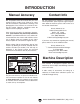
INTRODUCTION Manual Accuracy Contact Info We are proud to offer this manual with your new machine! We've made every effort to be exact with the instructions, specifications, drawings, and photographs of the machine we used when writing this manual. However, sometimes errors do happen and we apologize for them. We stand behind our machines. If you have any service questions, parts requests or general questions about the machine, please call or write us at the location listed below.
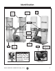
Identification Canister Filter Filter Cleaning Handle Filter Bag Collector Outlet Connector Collection Bag Caster Inlet Connector 3-Port Inlet Connector Motor To reduce the risk of serious injury when using this machine, read and understand this entire manual before beginning any operations. ON/OFF Paddle Switch Figure 1. Rear view identification. Figure 2. Model G0562Z/G1030Z2 identification. Model G0562Z/ZP, G1030Z2/Z2P (Mfg.
Machine Data Sheet MODEL G0562Z/G0562ZP, G1030Z2/1030Z2P DUST COLLECTORS Model Number G0562Z/G0562ZP G1030Z2/G1030Z2P 187 lbs. 156 lbs. 57-7/8 x 32 x 71 in. 49-1/2 x 21-1/2 x 78 in. Product Dimensions Weight Width (side-to-side)/Depth (frontto-back)/Height Foot Print (Width/Depth) 49-1/2 x 21-1/2 in. Shipping Dimensions Carton 1 Type Cardboard Content Weight Width (side-to-side)/Depth (frontto-back)/Height Machine 165 lbs. 170 lbs. 52 x 23 x 24 in. 51 x 22 x 23 in.
Model Number G0562Z/G0562ZP G1030Z2/G1030Z2P Operation Information Type Air Suction Capacity Canister Bag 2320 CFM 2300 CFM 16.9 in. 16.7 in. Maximum Static Pressure Main Inlet Size 7 in. Manifold Included Yes Manifold Inlets 3 Manifold Inlet Size 4 in. Maximum Material Collection Capacity 11.4 cu. ft. Canister or Upper Bag Filtration 1 Micron 2.5 Micron Bag Information Number of Upper Bags NA 2 Upper Bag Capacity NA 5.7 cu. ft. Upper Bags Total Area NA 5.7 cu. ft.
SECTION 1: SAFETY For Your Own Safety, Read Instruction Manual Before Operating this Machine The purpose of safety symbols is to attract your attention to possible hazardous conditions. This manual uses a series of symbols and signal words intended to convey the level of importance of the safety messages. The progression of symbols is described below. Remember that safety messages by themselves do not eliminate danger and are not a substitute for proper accident prevention measures.
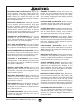
DISCONNECTING POWER SUPPLY. 6alVnh Y^h" XdccZXi bVX]^cZ [gdb edlZg hjeean WZ[dgZ hZg" k^X^c\! VY_jhi^c\! dg X]Vc\^c\ Xjii^c\ iddah W^ih! WaVYZh! XjiiZgh! ZiX# # BV`Z hjgZ hl^iX] ^h ^c D;; edh^i^dc WZ[dgZ gZXdccZXi^c\ id Vkd^Y Vc jcZmeZXi" ZY dg jc^ciZci^dcVa hiVgi# APPROVED OPERATION.
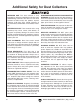
Additional Safety for Dust Collectors INTENDED USE. I]^h Yjhi XdaaZXidg ^h dcan ^ciZcYZY [dg XdaaZXi^c\ lddY Yjhi VcY X]^eh [gdb lddYldg`^c\ bVX]^cZh# 9D CDI jhZ i]^h Yjhi XdaaZXidg id XdaaZXi bZiVa! Y^gi! eZWWaZh! YgnlVaa! VhWZhidh! aZVY eV^ci! h^a^XV! a^fj^Yh! VZgdhdah! dg Vcn [aVbbVWaZ! XdbWjhi^WaZ! dg ]VoVgYdjh bViZg^" Vah# HAZARDOUS DUST.
SECTION 2: POWER SUPPLY Availability 7Z[dgZ ^chiVaa^c\ i]Z bVX]^cZ! Xdch^YZg i]Z VkV^a" VW^a^in VcY egdm^b^in d[ i]Z gZfj^gZY edlZg hjeean X^gXj^i# >[ Vc Zm^hi^c\ X^gXj^i YdZh cdi bZZi i]Z gZfj^gZbZcih [dg i]^h bVX]^cZ! V cZl X^gXj^i bjhi WZ ^chiVaaZY# Id b^c^b^oZ i]Z g^h` d[ ZaZXigdXj" i^dc! [^gZ! dg Zfj^ebZci YVbV\Z! ^chiVaaVi^dc ldg` VcY ZaZXig^XVa l^g^c\ bjhi WZ YdcZ Wn V fjVa^[^ZY ZaZXig^X^Vc ^c VXXdgYVcXZ l^i] Vaa Veea^XVWaZ XdYZh VcY hiVcYVgYh# Electrocution, fire, or equipment
Grounding Requirements I]^h bVX]^cZ BJHI WZ \gdjcYZY# >c i]Z ZkZci d[ XZgiV^c bVa[jcXi^dch dg WgZV`Ydlch! \gdjcY^c\ gZYjXZh i]Z g^h` d[ ZaZXig^X h]dX` Wn egdk^Y^c\ V eVi] d[ aZVhi gZh^hiVcXZ [dg ZaZXig^X XjggZci# I]^h bVX]^cZ ^h Zfj^eeZY l^i] V edlZg XdgY i]Vi ]Vh Vc Zfj^ebZci"\gdjcY^c\ l^gZ VcY V \gdjcY" ^c\ eaj\ h^b^aVg id i]Z [^\jgZ WZadl # I]Z eaj\ bjhi dcan WZ ^chZgiZY ^cid V bViX]^c\ gZXZeiVXaZ djiaZi i]Vi ^h egdeZgan ^chiVaaZY VcY \gdjcYZY ^c VXXdgYVcXZ l^i] Vaa adXVa
SECTION 3: SETUP Needed for Setup This machine presents serious injury hazards to untrained users. Read through this entire manual to become familiar with the controls and operations before starting the machine! Wear safety glasses during the entire setup process! This machine and its components are very heavy. Get lifting help or use power lifting equipment such as a forklift to move heavy items.
Inventory I]Z [daadl^c\ ^h V YZhXg^ei^dc d[ i]Z bV^c Xdbed" cZcih h]^eeZY l^i] ndjg bVX]^cZ# AVn i]Z Xdbed" cZcih dji id ^ckZcidgn i]Zb# >[ Vcn cdc"egdeg^ZiVgn eVgih VgZ b^hh^c\ Z#\# V cji dg V lVh]Zg ! lZ l^aa \aVYan gZeaVXZ i]Zb0 dg [dg i]Z hV`Z d[ ZmeZY^ZcXn! gZeaVXZbZcih XVc WZ dWiV^cZY Vi ndjg adXVa ]VgYlVgZ hidgZ# Inventory Item Qty A. Upper Collection Bags (G1030Z2/Z2P)....... 2 Canister Filter (G0562Z/ZP)........................ 2 B. Canister Filter Handle (G0562Z/ZP)............
Site Considerations Weight Load Physical Environment GZ[Zg id i]Z Machine Data Sheet [dg i]Z lZ^\]i d[ ndjg bVX]^cZ# BV`Z hjgZ i]Vi i]Z hjg[VXZ jedc l]^X] i]Z bVX]^cZ ^h eaVXZY l^aa WZVg i]Z lZ^\]i d[ i]Z bVX]^cZ! VYY^i^dcVa Zfj^ebZci i]Vi bVn WZ ^chiVaaZY dc i]Z bVX]^cZ! VcY i]Z ]ZVk^Zhi ldg`" e^ZXZ i]Vi l^aa WZ jhZY# 6YY^i^dcVaan! Xdch^YZg i]Z lZ^\]i d[ i]Z deZgVidg VcY Vcn YncVb^X adVY^c\ i]Vi bVn dXXjg l]Zc deZgVi^c\ i]Z bVX]^cZ# I]Z e]nh^XVa Zck^gdcbZci l]ZgZ i]Z bVX]^cZ ^h deZgV
Assembly 4. Place a rubber gasket around the impeller outlet rim, as shown in Figure 11. To assemble your dust collector: 1. Place the base upside down on a clean, flat surface (to avoid scratching the paint). 2. Gasket Attach the casters to the base with (16) 5⁄16"18 x 1⁄2" flange bolts, as shown in Figure 9. x 16 Figure 11. Positioning impeller outlet gasket. 5. Secure the metal "Y" outlet to the impeller outlet with (8) 5⁄16"-18 x 1⁄2" flange bolts, as shown in Figure 12. Figure 9.
6. Align each of the collector supports with the mounting holes on the base, as shown in Figure 13, then secure them in place with (4) 5 ⁄16"-18 x 1⁄2" flange bolts. 8. Attach the top of the canister support to the collector with (2) 5⁄16"-18 x 1⁄2" flange screws, as shown in Figure 14. G1030Z2/G1030Z2P only: Place the upper bag support over the canister support and secure it with (2) 5⁄16"-18 x 1⁄2" flange bolts, as shown in Figure 15. Collector Support Upper Bag Support Canister Support x4 Figure 13.
10. Affix the wide foam strip around the outside top rim of the collector, as shown in Figure 17. 13. G0562Z/G0562ZP only: a. Install the canister handle onto the top of the canister filter by tightening the bolt against the flat of the shaft (see Figure 20). Flat Figure 17. Installing wide foam strip. 11. Trim the excess foam strip so the ends come together evenly, as shown in Figure 18. Figure 20. Installing canister handle. b. Place the canister filter on top of the collectors. c.
G1030Z2/G1030Z2P only: a. Hook the top loop of the upper filter bags (fabric) over the upper bag supports, as shown in Figure 22. 14. Hook the clear collection bag on the hooks around the bottom of the collector to hold the bag in place for the next step. 15. Tighten the belt clamp around the narrow foam strip to seal and secure the lower collection bag (Figure 24). Note: DO NOT force the clamp. If it will not close, choose the next notch over, then clamp in place. Figure 22. Attaching upper filter bag.
Power Connection After you have completed all previous setup instructions and circuit requirements, the machine is ready to be connected to the power supply. Connecting Power 1. Turn the machine power switch OFF. 2. Insert the power cord plug into a matching power supply receptacle. The machine is now connected to the power source. To prevent accidental damage to the power cord, make sure it is kept away from potential damage sources at all times—whether connected or not.
Test Run Once the assembly is complete, test run your machine to make sure it runs properly and is ready for regular operation. 4. Turn the machine OFF. 5. Remove the switch disabling key, as shown in Figure 28. The test run consists of verifying the following: 1) The motor powers up and runs correctly, and 2) the safety disabling mechanism on the switch works correctly.
SECTION 4: DESIGNING THE SYSTEM General Always guard against static electrical build up by grounding all dust collection lines. The Model G0562Z/G0562ZP and G1030Z2/ G1030Z2P can be operated as either a stationary or a mobile unit. There are advantages and disadvantages to both set-ups. The advantage of the mobile system is eliminating the cost of many ducts and fittings. On the other hand, the stationary system is more versatile and convenient.
There are a number of options when it comes to metal duct, but metal duct that is specially manufactured for dust collection is the best choice. When selecting your metal duct, choose high quality metal duct with smooth welded internal seams that will minimize airflow resistance. This type of duct usually connects to other ducts or elbows with a simple, self-sealing clamp, is very quick and easy to assemble, and can be readily dismantled and re-installed.
System Design Step 1. Decide Who Will Design For most small-to-medium sized shops, you can design and build the dust collection system yourself without hiring engineers or consultants. We have included some basic information here to get you started on a basic design. If you have a large shop or end up designing a complicated system, then we recommend additional research beyond this manual, or that you seek the help of an expert. Step 3.
3. Directional changes should be kept to a minimum. The more directional change fittings you use directly increases the overall resistance to airflow. 4. Gradual directional changes are more efficient than sudden directional changes (i.e. use the largest corner radius possible when changing hose or pipe direction). 5. Each individual branch line should have a blast gate immediately after the branch to control suction from one machine to another. 6.
Determining Main Line Duct Size The general rule of thumb for a main line duct is that the velocity of the airflow must not fall below 3500 FPM. For small/medium sized shops, using the inlet size of the dust collector as the main line duct size will usually keep the air velocity above 3500 FPM and, depending on your system, will allow you to keep multiple branches open at one time.
Calculating Duct Resistance Adding duct work, elbows, branches and any other components to a duct line increases airflow resistance (static pressure loss). This resistance can be minimized by using rigid (smooth) pipe and gradual curves, as opposed to flexible pipe and 90˚ elbows. To help you think about this resistance, imagine riding a bicycle in a tunnel that is an exact replica of your duct work.
Note: When calculating static pressure loss to determine if multiple lines can be left open at the same time, only include the main line numbers once. 5. Compare the total static pressure loss for that line to the maximum static pressure loss found on the data sheet for your machine (located toward the front of this manual). —If the CFM for your static pressure loss is above the requirement of the machine, then the line will most likely be successful.
Be sure that you extend the bare copper wire down all branches of the system. Do not forget to connect the wires to each other with wire nuts when two branches meet at a “Y” or “T” connection. Ensure that the entire system is grounded. If using plastic blast gates to direct air flow, the grounding wire must be jumped (Figure 44) around the blast gate without interruption to the grounding system. External Ground Wire Internal Ground Wire Ground Screw Flex-Hose Figure 45. Flex-hose grounded to machine.
SECTION 5: OPERATIONS General To reduce the risk of serious injury when using this machine, read and understand this entire manual before beginning any operations. Damage to your eyes and lungs could result from using this machine without proper protective gear. Always wear safety glasses and a respirator when operating this machine. Operating the Model G0562Z/G0562ZP/G1030Z2/ G1030Z2P is simple and straightforward. Turn the dust collector ON, then turn the machine ON.
accessories SECTION 6: ACCESSORIES Some aftermarket accessories can be installed on this machine that could cause it to function improperly, increasing the risk of serious personal injury. To minimize this risk, only install accessories recommended for this machine by Grizzly. G1536—Black Flexible Hose 4" x 10' G2974—Wire Hose Clamp 4" G1843—Plastic Blast Gate 4" G4679—Anti-Static Grounding Kit We've hand picked a selection of commonly used dust collection components for machines with 4" dust ports.
H5293—4" Metal Duct Starter Kit H5295—5" Metal Duct Starter Kit H5297—6" Metal Duct Starter Kit Save over 20% with this great starter kit. Includes: (2) machine adapters, (10) pipe clamps, (3) 5' straight pipes, (1) branch, (3) pipe hangers, (1) end cap, (3) adjustable nipples, (1) 90˚ elbow, and (1) 60˚ elbow. Figure 49. Metal Duct Starter Kit.
Metal Branches We carry many different branches, all designed to minimize airflow resistance. H2499—Small Half-Mask Respirator H3631—Medium Half-Mask Respirator H3632—Large Half-Mask Respirator H3635—Cartridge Filter Pair P100 Wood dust has been linked to nasal cancer and severe respiratory illnesses. If you work aroundwood dust everyday, a half-mask respirator can be a lifesaver. Also compatible with safety glasses! Figure 53. Metal Branches.
SECTION 7: MAINTENANCE Always disconnect power to the machine before performing maintenance. Failure to do this may result in serious personal injury. Schedule For optimum performance from your machine, follow this maintenance schedule and refer to any specific instructions given in this section. Daily Check: • Loose mounting bolts. • Worn switch. • Worn or damaged wires. • Almost full collection bag. • Any other unsafe condition.
Emptying/Replacing Bags Cleaning Canister Filter Replacement plastic lower collection bags are available through Grizzly as Model T20543. Replacement upper collection bags are available for the Model G1030Z2/G1030Z2P as Model G5556. To clean the canister filter on the Model G0562Z/ G0562ZP, move the canister cleaning handle back and forth to free the trapped dust particles from the filter pleats (see Figure 58). The particles will fall into the collection bag.
SECTION 8: SERVICE Review the troubleshooting and procedures in this section if a problem develops with your machine. If you need replacement parts or additional help with a procedure, call our Technical Support at (570) 546-9663. Note: Please gather the serial number and manufacture date of your machine before calling.
Dust Collector Operation Symptom Possible Cause Possible Solution Dust collector does not adequately collect dust or chips; poor performance. 1. Dust collection bags are full. 2. Filter is dirty. 3. Restriction in duct line. 1. Empty collection bags. 2. Clean filter. 3. Remove restriction in the duct line. A plumbing snake may be necessary. 4. Relocate the dust collector closer to the point of suction, and rework ducting without sharp bends. Refer to System Design, beginning on Page 22. 5.
machine SECTION 9: WIRING I]ZhZ eV\Zh VgZ XjggZci Vi i]Z i^bZ d[ eg^ci^c\# =dlZkZg! ^c i]Z he^g^i d[ ^begdkZbZci! lZ bVn bV`Z X]Vc\" Zh id i]Z ZaZXig^XVa hnhiZbh d[ [jijgZ bVX]^cZh# 8dbeVgZ i]Z bVcj[VXijgZ YViZ d[ ndjg bVX]^cZ id i]Z dcZ hiViZY ^c i]^h bVcjVa! VcY hijYn i]^h hZXi^dc XVgZ[jaan# >[ i]ZgZ VgZ Y^[[ZgZcXZh WZilZZc ndjg bVX]^cZ VcY l]Vi ^h h]dlc ^c i]^h hZXi^dc! XVaa IZX]c^XVa Hjeedgi Vi *,% *)+".
Wiring Diagram HiVgi 8VeVX^idg *%%B;9 &'*K68 MOTOR I8= k^ZlZY [gdb WZ]^cY Ground < Hot 220 VAC Hot Figure 59. Switch. 6-20 Plug FIgure 60. Junction box and start capacitor. Model G0562Z/ZP, G1030Z2/Z2P (Mfg. 11/11+) Figure 61. Run capacitor.
SECTION 10: PARTS G0562Z/G1030Z2 Main Breakdown See H5783 Parts Breakdown on Page 39 '* ') '* &( (' (* G1030Z2 '* ') G0562Z &( '* '' (' (* '( G1030Z2 ' &- &+K' &*K' &( (' '% ' '.K' &+K'"( '% '( '- '& '+ &% ' (. &) && '& &+K'"& (&( ' ()K' (' )' &. G0562Z )% ' '( (, (+ .K' )( - ' && &, * + ) (( &+K'"* (% &+K'"' &+K'") &+K'"+ ', ', "& (& & ( ' -38- Model G0562Z/ZP, G1030Z2/Z2P (Mfg.
G0562Z/G1030Z2 Main Parts List REF PART # DESCRIPTION REF PART # DESCRIPTION 1 2 3 4 5 6 8 9V2 10 11 13 14 15V2 16V2 16V2-1 16V2-2 16V2-3 16V2-4 16V2-5 16V2-6 17 18 19 20 21 P1028Z2001 PFB01 P1030Z2003 PS06 P1030Z2005 PCAP121M P1028Z2009 P1029Z2010V2 P1028Z2011 PW07 PFB01 PB03 P1030Z2015V2 P1030Z2016V2 P1030016-1 P1030016-2 P1030Z2016V2-3 P1030Z2016V2-4 P1030Z2016V2-5 P1030Z2016V2-6 PN02 P1030018 P1030019 T20543 P1028Z2023 CASTER FLANGE BOLT 5/16-18 X 1/2 BASE PLATE PHLP HD SCREW 10-24 X 3/8" INLET C
G0562ZP/G1030Z2P Main Breakdown '* See H5783 Parts Breakdown on Page 39 ') '* &( (' (* G1030Z2P '* ') G0562ZP &( '* '' (' (* '( G1030Z2P &- )% ' (' ' '( &. G0562ZP &+ '- '& '+ &% ' (' (. &) && '% '& ' '% '( &* &( )' )& (&( ' () (, (+ . )( - ' && &, * + ) (( '. &+"& &+"( &+"* &+"' &+") -40- (% ', ',"& (& &+"+ & ' ( Model G0562Z/ZP, G1030Z2/Z2P (Mfg.
G0562ZP/G1030Z2P Main Parts List REF PART # DESCRIPTION REF PART # DESCRIPTION 1 2 3 4 5 6 8 9 10 11 13 14 15 16 16-1 16-2 16-3 16-4 16-5 16-6 17 18 19 20 21 CASTER FLANGE BOLT 5/16-18 X 1/2 BASE PLATE PHLP HD SCREW 10-24 X 3/8" INLET COVER 7" CAP SCREW M6-1 X 20 LH IMPELLER WASHER IMPELLER 12-3/4" ALUMINUM COLLECTOR BODY FLAT WASHER 5/16 FLANGE BOLT 5/16-18 X 1/2 HEX BOLT 5/16-18 X 1 PADDLE SWITCH MOTOR 3HP 220V 1PH MOTOR FAN COVER MOTOR FAN CAPACITOR COVER S CAPACITOR 500M 125V JUNCTION BOX R CAPACIT
-42- Model G0562Z/ZP, G1030Z2/Z2P (Mfg.
WARRANTY CARD CVbZ TTTTTTTTTTTTTTTTTTTTTTTTTTTTTTTTTTTTTTTTTTTTTTTTTTTTTTTTTTTTTTTTTTTTTTTTTTTTT HigZZi TTTTTTTTTTTTTTTTTTTTTTTTTTTTTTTTTTTTTTTTTTTTTTTTTTTTTTTTTTTTTTTTTTTTTTTTTTTTT 8^in TTTTTTTTTTTTTTTTTTTTTTT HiViZ TTTTTTTTTTTTTTTTTTTTTTTTT O^e TTTTTTTTTTTTTTTTTTTTT E]dcZ TTTTTTTTTTTTTTTTTTTT :bV^a TTTTTTTTTTTTTTTTTTTTTTTT >ckd^XZ TTTTTTTTTTTTTTTTT BdYZa TTTTTTTTTTTTTTTTTTTT DgYZg TTTTTTTTTTTTTTTTTTTTTTT HZg^Va TTTTTTTTTTTTTTTTTT The following information is given on a voluntary basis.
;DA9 6ADC< 9DII:9 A>C: EaVXZ HiVbe =ZgZ '2)::,9 ).$5342)!, ).# 0 / "/8 "%,,).
WARRANTY AND RETURNS 7!22!.49 !.$ 2%452.
Buy Direct and Save with Grizzly ® – Trusted, Proven and a Great Value! ~Since 1983~ Visit Our Website Today For Current Specials! ORDER 24 HOURS A DAY! 1-800-523-4777