0" TABLE SAW MODEL G0444/G0444Z INSTRUCTION MANUAL COPYRIGHT © OCTOBER 2003 BY GRIZZLY INDUSTRIAL, INC. WARNING: NO PORTION OF THIS MANUAL MAY BE REPRODUCED IN ANY SHAPE OR FORM WITHOUT THE WRITTEN APPROVAL OF GRIZZLY INDUSTRIAL, INC. #5456 PRINTED IN TAIWAN ONLINE MANUAL DISCLAIMER THE INFORMATION IN THIS MANUAL REPRESENTS THE CONFIGURATION OF THE MACHINE AS IT IS CURRENTLY BEING SHIPPED. THE MACHINE CONFIGURATION CAN CHANGE AS PRODUCT IMPROVEMENTS ARE INCORPORATED.
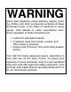
WARNING Some dust created by power sanding, sawing, grinding, drilling, and other construction activities contains chemicals known to the State of California to cause cancer, birth defects or other reproductive harm. Some examples of these chemicals are: • Lead from lead-based paints. • Crystalline silica from bricks, cement, and other masonry products. • Arsenic and chromium from chemically treated lumber. Your risk from these exposures varies, depending on how often you do this type of work.
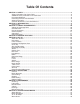
Table Of Contents SECTION 1: SAFETY........................................................................................................................3 Safety Instructions For Power Tools ..........................................................................................3 Additional Safety Instructions For Table Saws ..........................................................................5 Preventing Kickback......................................................................................
SECTION 9: REFERENCE INFO ....................................................................................................46 General ....................................................................................................................................46 Aftermarket Accessories ..........................................................................................................46 G0444 Machine Data Sheet...................................................................................
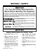
SECTION 1: SAFETY For Your Own Safety Read Instruction Manual Before Operating This Equipment The purpose of safety symbols is to attract your attention to possible hazardous conditions. This manual uses a series of symbols and signal words which are intended to convey the level of importance of the safety messages. The progression of symbols is described below. Remember that safety messages by themselves do not eliminate danger and are not a substitute for proper accident prevention measures.
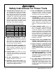
Safety Instructions For Power Tools 9. USE PROPER EXTENSION CORD. Make sure your extension cord is in good condition. Conductor size should be in accordance with the chart below. The amperage rating should be listed on the motor or tool nameplate. An undersized cord will cause a drop in line voltage resulting in loss of power and overheating. Your extension cord must also contain a ground wire and plug pin. Always repair or replace extension cords if they become damaged.
Additional Safety Instructions For Table Saws 1. 2. 3. 4. 5. 6. BLADE GUARD. Always use the blade guard on all ''through-sawing'' operations. Through-sawing operations are those when the blade cuts completely through the workpiece. KICKBACK. Be familiar with kickback. Kickback happens when the workpiece is thrown towards the operator at a high rate of speed. Until you have a clear understanding of kickback and how it occurs, DO NOT operate this table saw! WORKPIECE CONTROL.
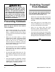
Statistics prove that most common accidents among table saw users can be linked to kickback. Kickback is typically defined as the high-speed expulsion of stock from the table saw toward its operator. In addition to the danger of the operator or others in the area being struck by the flying stock, it is often the case that the operator’s hands are pulled into the blade during the kickback. Preventing Kickback Below are tips to avoid the most common causes of kickback: • Never attempt freehand cuts.
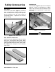
Safety Accessories Push Sticks The use of a push stick (Figure 1), particularly when cutting small or narrow workpieces, provides an added level of safety for the operator. See the template at the end of the manual for construction details, or purchase one from the Grizzly catalog. Featherboards Featherboards (Figure 3) help prevent workpiece kickback. To make a featherboard, cut a 30-40° angle at one end of the board, and make a number of end cuts at approximately 1⁄4" apart and 2" to 3" deep. Figure 3.
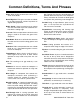
Common Definitions, Terms And Phrases Arbor: Metal shaft that connects the drive mechanism to the blade. Bevel Edge Cut: Tilting the saw arbor and blade to an angle between 0° and 45° to perform an angled cutting operation. Blade Guard: Guard mechanism that mounts over the saw blade to prevent accidental contact with the cutting edge. Crosscut: Table saw operation in which the miter gauge is used to cut across the grain of the workpiece.
SECTION 2: INTRODUCTION Commentary Lack of familiarity with this manual could cause serious personal injury. Become familiar with the contents of this manual, including all the safety warnings. We are proud to offer the Model G0444/G0444Z 10" Table Saw. This machine is part of a growing Grizzly family of fine woodworking machinery.
SECTION 3: CIRCUIT REQUIREMENTS Voltage & Amperage Draw Plug & Receptacle The following list and figures outline the correct plug and receptacle to use: The following list outlines the voltage required to operate the saws, as well as the amperage draw of their motors: G0444 110V (prewired) .................................... 18 Amps 220V ...................................................... 9 Amps G0444 110V (prewired)................................ NEMA 5-15 220V......................................
G0444Z 110V................................................ NEMA 5-30* 220V (prewired) .............................. NEMA 6-15* *Not Included If the circuit breaker trips or the fuse blows regularly, your machine may be operating on a circuit that is close to its amperage draw capacity. However, if an unusual amperage draw does not exist and a power failure still occurs, contact a qualified electrician. Grounding Figure 6. NEMA 5-30 plug and receptacle.
SECTION 4: MACHINE FEATURES D C E B F A G Figure 8. Front view. A. B. C. D. E. F. G.
SECTION 5: SET UP About this Section Parts Inventory The purpose of this section is to guide you through the required steps to get your machine out of its packaging and into operating condition. DESCRIPTION QTY Hand Tool Hardware Bag: • Combo Wrench 12 x 13 ..............................1 • Arbor Wrench 23mm....................................1 • Hex Key 2mm ..............................................1 • Hex Key 3mm ..............................................1 • Hex Key 4mm ........................
C P E F L J D B K I H O M N Figure 9. Parts layout. DESCRIPTION QTY A. Table Saw Unit (Not Shown) ..................1 B. V-Belt Guard............................................1 C. Motor ......................................................1 D. Stand Accessory Hanger Package..........1 E. Motor Plate ..............................................1 F. Motor Bracket ..........................................1 G. Motor Pivot Shaft (Not Shown)................1 H. Blade Guard Mounting Bracket*.....
Q U P Y X O V T T S S W R R Figure 10. Parts layout. DESCRIPTION QTY O. Table Insert - Standard ..........................1 P. Table Insert - Dado ................................1 Q. Cast Iron Extension Wings (G0444Z) ....2 R. Handwheels ............................................2 S. Threaded Handles 3⁄8"-16 x 1⁄2"................2 T. Star Knobs 3⁄8"-16....................................2 U. Stand Legs ..............................................4 V. Top Short Bracket .......................
10 WASH Button Head Screw Flange Bolt ⁄ '' 7 16 23⁄4'' 3 WASH S WA H ASH 8mm ASH W ASHE 6mm DI ER ASH ASHE R DIA ⁄ '' 14 D ER I ASH 21⁄2'' DIA ER ⁄ '' 5 16 ET AM LINES ARE 1⁄16'' INCH APART LINES ARE 1MM APART 21⁄4'' 10mm R DIA ET AM 2 4mm MET 13⁄4'' ⁄ '' 38 METE 11⁄2'' D ER IA TE ME R 16mm ⁄ '' ⁄ '' ⁄ '' ⁄ '' ⁄ '' 1'' 11⁄4'' 5 16 7 16 9 16 34 78 MET 12mm '' '' '' '' ET AM 10mm ⁄ ⁄ ⁄ ⁄ 14 38 12 58 DI ER ETER M 8mm 5mm 10mm 15mm 20mm 25mm 30mm 35mm 40mm 4
Clean Up Site Considerations The unpainted surfaces are coated with a waxy oil to protect them from corrosion during shipment. Remove this protective coating with a solvent cleaner or citrus-based degreaser such as Grizzly’s G7895 Degreaser. To clean thoroughly, some parts may need to be removed. For optimum performance from your machine, make sure you clean all moving parts or sliding contact surfaces that are coated.
Beginning Assembly Stand This section will cover the basic assembly and adjustment instructions needed to begin operation. Complete the assembly in the order provided in this manual and then read the remaining portion of the manual before attempting any type of operation. Components and Hardware Needed: Qty Saw ....................................................................1 Stand Legs ........................................................4 Side Supports • Long Flat ...............................
3. Place the long “L” side supports over the ends of the short “L” side supports. 4. Using a 12mm wrench, secure all four “L” side supports to the saw body with 4 hex bolts, 8 flat washers, 4 lock washers, and 4 hex nuts. 5. Secure each stand leg to the outside of the “L” side supports with 24 carriage bolts, 24 flat washers, 24 lock washers, and 24 hex nuts (Figure 13). Stand Leg Rubber Feet Components and Hardware Needed: Qty Rubber Feet........................................................
Dust Port Handwheels Components and Hardware Needed: Qty Dust Port ............................................................1 Phillips Head Screws #10-24 x 5⁄8" ....................2 Hex Nuts #10-24 ................................................2 Exterior Tooth Washers #10 ..............................2 Toggle Tabs........................................................2 Components and Hardware Needed: Qty Handwheels ........................................................
Motor Components and Hardware Needed: Qty Motor ..................................................................1 Motor Plate ........................................................1 Motor Bracket ....................................................1 Motor Bracket Shaft............................................1 V-Belt Plate ........................................................1 V-Belt Guard ......................................................1 Hex Bolts 5⁄16"-18 x 1 ..............................
6. Tighten the hex nut on the motor bracket to secure the motor bracket shaft into place. 7. Slide the motor assembly onto the two shafts protruding from the back of the saw (Figure 21). 10. Place a straightedge across the arbor pulley and the motor pulley. The straightedge should align across the face of both pulleys (Figure 23). ! Setscrews Shafts Figure 23. V-belt alignment. Figure 21. Installed motor assembly. 8. 9.
— If either extension wing tilts up, loosen it and place a strip of masking tape along the top edge of the table (Figure 26). Extension Wings Components and Hardware Needed: Qty Extension Wings ................................................2 Hex Bolts 7⁄16"-14 x 11⁄4" ......................................6 Lock Washers 7⁄16" ..............................................6 Flat Washers 7⁄16" ................................................6 Tools Needed: 17mm Wrench or Socket ............................
Blade Fence Components and Hardware Needed: Qty Blade (Not Included) ..........................................1 Arbor Nut (Left Hand Threads) ..........................1 Arbor Flange ......................................................1 Install the Shop Fox® fence and rails according to the fence manual. Tools Needed: 23mm Wrench ....................................................1 Switch To install the blade guard: 1. Using a 23mm wrench, loosen the arbor nut.
Miter Gauge Blade Guard Components and Hardware Needed: Qty Miter Gauge Body ..............................................1 Miter Bar ............................................................1 Threaded Handle 5⁄16"-18 x 1" ............................1 Flat Washer 5⁄16"..................................................1 Components and Hardware Needed: Qty Blade Guard ......................................................1 Blade Guard Mounting Bracket Assembly..........1 Blade Guard Mounting Shaft ...
3. 4. Using a 12mm wrench, secure the blade guard mounting bracket to the blade guard mounting shaft by tightening the hex bolts on the bracket. Note—Do not worry about precise placement at this time. 7. Place a straightedge against the face of the saw blade and the blade guard (Figure 33). ! Slide the blade guard fingers onto the blade guard mounting bolts (Figure 31). Blade Guard Mounting Bolts Support Shaft Blade Guard Figure 31. Blade guard components. 5.
Table Insert Components and Hardware Needed: Qty Standard Blade Table Insert ..............................1 Dado Blade Table Insert ....................................1 Tools Needed: 3mm Allen Wrench ............................................1 Proper Alignment Figure 35. Correct blade guard alignment. 8. Repeat steps 6-7. 9. Adjust the saw blade through its complete tilt and height adjustments. The saw blade should not make contact with any part of the blade guard.
Power Cord ! Disconnect power to the machine during the entire assembly process. Failure to do this may result in serious personal injury. G0444 The Model G0444 ia prewired to operate on a 110V power source. Connect the power cord to the motor according to Figure 37. G0444Z The Model G0444Z ia prewired to operate on a 220V power source. Connect the power cord to the motor according to Figure 38.
Start Up Loose hair and clothing could get caught in machinery causing serious personal injury. Keep loose clothing rolled up and long hair tied up and away from machinery. Figure 38b. Locked power switch Projectiles thrown from the machine could cause serious eye injury. Wear safety glasses during assembly. Recommended Adjustments Before starting the machine: 1. Read the entire instruction manual. 2. Make sure the blade guard and splitter are installed and correctly adjusted. 3.
SECTION 6: OPERATIONS General Damage to your eyes, lungs, and ears could result from failure to wear safety glasses, a respirator, and hearing protection while sanding with this machine. Loose hair and clothing could get caught in machinery and cause serious personal injury. Keep loose clothing rolled up and long hair tied up and away from machinery. Keep the blade guard in the down position at all times. Failure to do this could result in serious personal injury or death.
Combination blade features: • Adequate for cutting both with and across the grain. • 40-50 teeth. • Alternate top bevel and flat, or alternate top bevel and raker tooth profile. • Teeth are arranged in groups of five. • Gullets are small and shallow within the groups of five teeth, similar to a cross-cut blade; then large and deep between each group of five, like a ripping blade. Dado Blades: There are two types of dado blades: stacked and wobble.
Crosscutting Crosscutting means cutting across the grain of the workpiece. In workpieces without grain (i.e. MDF, particleboard) crosscutting simply means cutting across the width of the workpiece. 6. Turn on the saw and allow it to reach full speed. 7. Hold the workpiece firmly against the face of the miter gauge and ease it into the blade as shown in Figure 44. Crosscuts are made with the miter gauge. There are two miter gauge slots in the table top.
Ripping 8. Using a push stick, feed the workpiece through the saw blade as shown in Figure 45, until the workpiece is completely past the saw blade. Ripping means cutting with the grain of the workpiece. In other materials such as MDF or plywood, ripping simply means cutting lengthwise. To make a rip cut: 1. Set the fence to the desired width of cut on the scale. 2. Adjust the blade height so the highest saw tooth protrudes approximately 1⁄4" above the workpiece. 3.
Dado Cutting Commonly used in furniture joinery, a dado is a straight channel cut in the face of the workpiece. Dadoes can be cut using either a dedicated dado blade or a standard saw blade. Dado operations present very real hazards requiring proper procedures to avoid serious injury. The chance of kickback is always greater when dado blades are used so extra care must be taken. Any movement of the workpiece away from the fence will cause kickback. Be certain that stock is flat and straight.
7. Reconnect the saw to the power source. 8. With one finger ready to push the STOP button, turn the saw ON. The blade should run smooth with no vibrations or wobbling. 9. When the blade has reached full speed, perform a test cut with a scrap piece of wood. 6. Re-adjust the fence so the blade is aligned with the other edge of the intended dado channel (Figure 48). Note—Be sure to keep the cuts within your marks; otherwise, the dado will be too big. 10.
Rabbet Cutting Commonly used in furniture joinery, a rabbet is a L-shaped groove cut in the edge of the workpiece. Rabbets can be cut with either a dado blade or a standard saw blade. Cutting rabbets with the dado blade: 1. Adjust the saw blade to the maximum height needed for the rabbeting operation. 2. Adjust the fence and align the workpiece to perform the cutting operation as shown in Figure 50.
Cutting rabbets with the standard blade: 4. Turn the saw ON. Note—Cutting rabbets with a standard saw blade DOES NOT require the use of a sacrificial fence. 5. When the blade has reached full speed, perform a test cut with a scrap piece of wood. Clearly mark the width of the rabbet cut on the workpiece. Note—Include marks on the edge of the workpiece to clearly identify the intended cut while it is laying flat on the saw table. 6. If the cut is satisfactory, repeat the cut with the final workpiece.
SECTION 7: MAINTENANCE ! Lubrication Always disconnect power to the machine before performing maintenance. Failure to do this may result in serious personal injury. Lubricate the areas indicated below every 12 months. 1. Blade angling trunnions. These should be lubricated with 6 or 7 drops of light machine oil. 2. Clean the Model G0444/G0444Z according to the schedule below to ensure maximum performance. Note—The following maintenance schedule assumes the saw is being used every day.
V-Belts Bearings To ensure optimum power transmission from the motor to the blade, the V-belt must be in good condition (free from cracks, fraying and wear). Check the V-belt at least every 3 months; more often if the saw is used daily. The bearings are sealed and pre-lubricated and require no lubrication during their usable life. However, your saw components will operate at their best if the bearing surfaces are kept clean.
Maintenance Log Date -40- Approximate Hours Of Use Maintenance Performed G0444/G0444Z 10" Table Saw
SECTION 8: SERVICE ADJUSTMENTS ! ! Always disconnect power to the machine before performing service adjustments. Failure to do this may result in serious personal injury. Front About Service This section is designed to help the operator with adjustments that were made at the factory and that might also need to be made during the life of the machine. A Figure 53. 90° blade parallelism measurement. 4.
Tilt the blade to 45° and repeat Steps 3-5. 6. 11. Refer back to the measurements taken in steps 3-6. — If the difference was less than 0.004" when the blade was positioned at 90˚ and 45˚, then the blade parallelism is set correctly. Skip to the next sub-section. — If the blade was not parallel in the 90˚ position, then proceed to the set of instructions titled “To Shift The Trunnion.
! 45˚ Bevel #1 3. Tighten down one trunnion bolt a small amount and then move on to each of the others, tightening each down the same amount. 4. Continue to rotate through the bolts, tightening them a little each time until they are all secure. 5. Flip the saw rightside up and repeat steps 26 on page 41. 6. Once the miter slot is adjusted parallel to the blade, recheck all measurements and be sure the table mounting bolts are secure. 7. Re-attach the blade guard and the fence. 8.
6. 45˚ & 90˚ Stops If a gap exists at either the top or bottom of the square, loosen the lock nut (A) and adjustment bolt (B) shown in Figure 59. The Model G0444/G0444Z Table Saw is equipped with positive stops at 45° and 90°. When properly adjusted, they provide quick and precise guides for blade bevel adjustment. D Use caution and remain alert when working around the saw blade. Failure to follow this warning could result in serious personal injury or death. To set the 45˚ & 90˚ stops: 1.
Worm Gears The worm gears on the blade tilt and height handwheel shafts can be adjusted to reduce “play” between the worm gear and the trunnion teeth. To adjust the blade height worm gear: 1. Disconnect the machine from the power source! 2. Remove the blade height handwheel. 3. Remove the roll pin that is inserted in the handwheel shaft. 4. Slide the various washers and accessories off the shaft to reveal the “flats” of the threaded bushing. To adjust the blade tilt worm gear: 1.
SECTION 9: REFERENCE INFO General This section contains the following subsections for the Model G0444/G0444Z: aftermarket accessories, data sheets, wiring diagrams, parts diagrams and list, troubleshooting, and warranty/return information. Aftermarket Accessories Heavy-Duty SHOP FOX® Mobile Base - G7314 Make your machine mobile with this popular patented mobile base. If you need parts or help in assembling your machine, or if you need operational information, call the service department at (570) 546-9663.
SHOP FOX® Push Stick - H3308 Measuring 131⁄2" overall, this push stick allows the operator to keep their hands at a safe distance away from the blade or cutter. OxiSolv® Blade & Bit Cleaner - G1955 Used to clean the gummy pitch and residue from saw blades and router bits, this high quality cleaner will make blades and bits last longer while improving cutting action. Figure 62. H3308 SHOP FOX® Push Stick. Figure 64. G1955 OxiSolv®.
MACHINE DATA SHEET Customer Service #: (570) 546-9663 • To Order Call: (800) 523-4777 • Fax #: (800) 438-5901 MODEL G0444 CONTRACTOR STYLE SAW Design Type...................................................................................................... Floor Model Overall Dimensions: Table Height ............................................................................................................35" Table Size ......................................................................................
MACHINE DATA SHEET Customer Service #: (570) 546-9663 • To Order Call: (800) 523-4777 • Fax #: (800) 438-5901 MODEL G0444Z CONTRACTOR STYLE SAW Design Type...................................................................................................... Floor Model Overall Dimensions: Table Height ............................................................................................................35" Table Size .....................................................................................
-50- G0444/G0444Z 10" Table Saw 148 9 11 39 41 45 37 162 149150 42 43 153 10 154 41a 40 33 31 35 32 44 36 42A 34 46 38A 38 113 15 14 155 157 8 112 1A 1 9 152 12 13 3 5 4 151 2 19 18 17 161 6 29 7 16 7 30 6 25 21 22A 18 23 7 22 24 128 15 26 6 29 28 6 27
G0444/G0444Z 10" Table Saw -51- 49 47 48 51 56 128 53 52 59 69 63 64 62 60 57 126 70 68 61 67 58 54 66 72 125 82 48 54 123 124 55 121 73 81 51 47 60 71 74 49 86 75 76 87 77 85 79 88 78 80 115 122 89 121 99 102 104 103 117 90 91 92 87 101 84 94 121 100 116 93 118 119 106 105 104 111 160 127 98 97 96 95 120 107 110 108 114 109
146 143 145 144 132 141 139 147 130 156 138 139 142 131 129 136 137 139 141 134 133 135 -52- G0444/G0444Z 10" Table Saw
REF 1A 1 2 3 4 5 6 7 8 9 9 10 11 12 13 14 15 16 17 18 19 21 22 22A 23 24 25 26 27 28 29 30 31 32 33 34 35 36 37 38 38A 39 40 41 41A 42 43 44 45 46 47 48 PART # P0444001A P0444001 P0444002 PSS04 P0444004 P0444005 PW07 PB32 P0444008 P0444009 P0444Z009 PLW05 PB90 P0444012 PS35 PW07 PN02 P0444016 P0444017 P0444018 P0444019 P0444021 P0444022 P0444022A P0444023 P0444024 P0444025 P0444026 P0444027 PB12 PLW01 P0444030 PW07 P0444032 PN14 PS21 P0444035 PFH09 P0444037 P0444038 PSS34 P0444039 P0444040 PRP14M PSS11 P04
REF 103 104 105 106 107 108 109 110 111 111 112 112 113 114 114 115 116 117 118 119 120 121 122 123 124 125 126 127 128 128B 128A 129 PART # PB03 PW07 PLW01 PN02 P0444107 PSS11 P0444109 PK23M P0444111 P0444Z111 PWRCRD110L PWRCRD220L P0444113 PWRCRD110S PWRCRD220S PCB04 P0444116 P0444117 P0444118 PW06 PWN02 PN09 P0444122 PN08 P0444124 PWR23 PWR1213 PB05 PAW02M PAW04M PAW03M P0444129 -54- DESCRIPTION HEX BOLT 5⁄16-18 X 1 FLAT WASHER 5⁄16" LOCK WASHER 5⁄16" HEX NUT 5⁄16-18 MOTOR PULLEY SETSCREW 1⁄4-20 X 1⁄4
Troubleshooting SYMPTOM POSSIBLE CAUSE Motor will not start. 1. 2. 1. Low voltage. Open circuit in motor or loose con- 2. nections. Check power line for proper voltage. Inspect all lead connections on motor for loose or open connections. Motor will not start; fuses or 1. 2. circuit breakers blow. 1. Short circuit in line cord or plug. Short circuit in motor or loose con- 2. nections. Incorrect fuses or circuit breakers in 3. power line. Inspect cord or plug for damaged insulation and shorted wires.
G0444 & G0444Z Wiring Diagrams NOTE: THE WIRES FROM THE POWER SUPPLY, EXCEPT THE GREEN GROUND WIRE, ARE INTERCHANGABLE, THEREFORE COLORS ARE NOT SPECIFIED. Disconnect power from machine before performing any electrical service. Failure to do this will result in a shock hazard, leading to injury or death.
Warranty & Returns Grizzly Industrial, Inc. warrants every product it sells for a period of 1 year to the original purchaser from the date of purchase. This warranty does not apply to defects due directly or indirectly to misuse, abuse, negligence, accidents, repairs or alterations or lack of maintenance.
WARRANTY CARD Name ____________________________________________________________________________________ Street ____________________________________________________________________________________ City ______________________________________________________________State________Zip_________ Phone Number_______________________E-Mail_______________________FAX________________________ MODEL #_____________________Serial # __________________________ Order #______________________ The following information is given on
FOLD ALONG DOTTED LINE Place Stamp Here GRIZZLY INDUSTRIAL, INC. P.O.
Buy Direct and Save with Grizzly® – Trusted, Proven and a Great Value! Visit Our Website Today And Discover Why Grizzly® Is The Industry Leader! • SECURE ORDERING • ORDERS SHIPPED WITHIN 24 HOURS • E-MAIL RESPONSE WITHIN ONE HOUR -OR- Call Today For A FREE Full Color Catalog