37" DRUM SANDER MODEL G0449/G0450 INSTRUCTION MANUAL COPYRIGHT © JUNE, 2005 BY GRIZZLY INDUSTRIAL, INC. REVISED APRIL, 2007 (BL) WARNING: NO PORTION OF THIS MANUAL MAY BE REPRODUCED IN ANY SHAPE OR FORM WITHOUT THE WRITTEN APPROVAL OF GRIZZLY INDUSTRIAL, INC.
WARNING Some dust created by power sanding, sawing, grinding, drilling, and other construction activities contains chemicals known to the State of California to cause cancer, birth defects or other reproductive harm. Some examples of these chemicals are: • Lead from lead-based paints. • Crystalline silica from bricks, cement, and other masonry products. • Arsenic and chromium from chemically treated lumber. Your risk from these exposures varies, depending on how often you do this type of work.
Table of Contents INTRODUCTION ............................................................................................................................... 3 Foreword .................................................................................................................................... 3 Contact Info ................................................................................................................................ 3 Machine Data .................................................
Lubrication ................................................................................................................................ 26 SECTION 7: SERVICE ................................................................................................................... 28 About Service ........................................................................................................................... 28 Troubleshooting..........................................................................
INTRODUCTION Foreword Contact Info We are proud to offer the Model G0449/G0450 37" Drum Sander. This machine is part of a growing Grizzly family of fine woodworking machinery. When used according to the guidelines set forth in this manual, you can expect years of trouble-free, enjoyable operation and proof of Grizzly’s commitment to customer satisfaction.
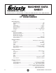
MACHINE DATA SHEET Customer Service #: (570) 546-9663 • To Order Call: (800) 523-4777 • Fax #: (800) 438-5901 MODEL G0449 37" DRUM SANDER Design Type ..................................................................................................... Floor Model Overall Dimensions: Width With Handle ................................................................................................... 68" Height ..................................................................................................
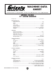
MACHINE DATA SHEET Customer Service #: (570) 546-9663 • To Order Call: (800) 523-4777 • Fax #: (800) 438-5901 MODEL G0450 37" DRUM SANDER Design Type ..................................................................................................... Floor Model Overall Dimensions: Width With Handle ................................................................................................... 68" Height ..................................................................................................
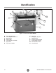
Identification F H G I E D J C K N L B A M Figure 1. Front view, Model G0449. A. B. C. D. E. F. G. -6- Table Height Shaft Table Height Handwheel Depth Scale Lifting Hook Table Height Lock Knob Top Cover Top Cover Handle H. I. J. K. L. M. N.
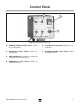
Control Panel B C A D F E Figure 2. Control panel close-up. A. SANDING DRUMS START Button—Starts the sanding drums. E. CONVEYOR STOP Button—Stops the conveyor belt. B. CONVEYOR START Button—Starts the conveyor belt. F. SANDING DRUMS STOP Button—Stops the sanding drums. C. AMP DRAW Meter—Displays the combined amperage draw of both motors. D. EMERGENCY STOP Button—Stops all machine functions.
SECTION 1: SAFETY For Your Own Safety, Read Instruction Manual Before Operating this Machine The purpose of safety symbols is to attract your attention to possible hazardous conditions. This manual uses a series of symbols and signal words which are intended to convey the level of importance of the safety messages. The progression of symbols is described below. Remember that safety messages by themselves do not eliminate danger and are not a substitute for proper accident prevention measures.
Safety Instructions for Machinery 7. ONLY ALLOW TRAINED AND PROPERLY SUPERVISED PERSONNEL TO OPERATE MACHINERY. Make sure operation instructions are safe and clearly understood. 8. KEEP CHILDREN AND VISITORS AWAY. Keep all children and visitors a safe distance from the work area. 9. MAKE WORKSHOP CHILD PROOF. Use padlocks, master switches, and remove start switch keys. 10. NEVER LEAVE WHEN MACHINE IS RUNNING.
Additional Safety for Drum Sanders 1. 2. FEEDING STOCK. DO NOT allow anyone to stand at the outfeed end when feeding your stock. Never sand more than one piece of stock at a time. 6. DUST COLLECTION SYSTEM. Never operate the sander without an adequate dust collection system in place and running. DO NOT jam the workpiece into the machine during operation. Firmly grasp the workpiece in both hands and ease it into the machine using light pressure. 7. BE ATTENTIVE.
SECTION 2: CIRCUIT REQUIREMENTS G0449 G0450 at 220V Serious personal injury could occur if you connect the machine to the power source before you have completed the set up process. DO NOT connect the machine to the power source until instructed to do so. Serious personal injury could occur if you connect your machine to the power source before you have completed the set up process. DO NOT connect the machine to the power source until instructed to do so.
G0450 at 440V Serious personal injury could occur if you connect your machine to the power source before you have completed the set up process. DO NOT connect the machine to the power source until instructed to do so. Power Connection Because of the high amperage draw from this machine, we recommend that you hardwire it directly to your circuit breaker and install a locking shut-off lever (see Figure 3) near the machine as a way to quickly disconnect the power and prevent accidental starting.
Grounding Rewiring to 440V In the event of an electrical short, grounding reduces the risk of electric shock. The grounding wire in the power cord must be properly connected to the grounding prong on the plug; likewise, the outlet must be properly installed and grounded. All electrical connections must be made in accordance with local codes and ordinances. The Model G0450 can be rewired for 440V operation.
SECTION 3: SET UP Set Up Safety This machine presents serious injury hazards to untrained users. Read through this entire manual to become familiar with the controls and operations before starting the machine! Wear safety glasses during the entire set up process! The Model G0449/G0450 has a shipping weight of 1190/1275 lbs. Serious personal injury may occur if safe moving methods are not followed.
Site Considerations Inventory After all the parts have been removed from the box, you should have the following items: Inventory: (Figure 4) Qty A. Drum Sander .............................................. 1 B. Control Panel .............................................. 1 C. Top Cover ................................................... 1 D. Spring Tension Tools .................................. 2 E. Handwheel .................................................
Mounting Control Panel Attaching Top Cover Components and Hardware Needed: Qty Drum Sander ..................................................... 1 Top Cover .......................................................... 1 To attach the top cover to the drum sander: 1. Remove the four button head cap screws and washers shown in the rear view of Figure 6. 2. Remove the two button head cap screws and washers shown in the front view of Figure 6. Components and Hardware Needed: Qty Control Panel ...............
Placing Sander The Model G0449/G0450 has a shipping weight of 1190/1275 lbs. Serious personal injury may occur if safe moving methods are not followed. To be safe, get assistance and use power equipment when moving the crate and removing the machine from the crate. Mounting to Floor Although not required, we recommend that you mount your new machine to the floor. Because this is an optional step and floor materials may vary, floor mounting hardware is not included.
Installing Handwheel Dust Collection Components and Hardware Needed: Qty Handwheel ........................................................ 1 This drum sander requires a minimum of 1600 CFM at the sander. We recommend using a dust collection system that produces a minimum of 2000 CFM. A fine layer of dust will be present on your stock as it comes out of the sander. This is normal. To mount the handwheel: 1.
Power Cord Before installing the power cord, read through SECTION 2: CIRCUIT REQUIREMENTS to check that your setup follows the safety and circuit requirements, and the power cord and power disconnect that you have chosen meet the requirements for this machine. Components and Hardware Needed: Qty Power Cord (Not Included) .................................1 To connect the sander to the power source: 1. Remove the screws securing the control panel and lift off the face plate. Figure 14.
Test Run Now that the machine is connected to the power source, it is important to perform a test run to make sure all the controls are working properly. Before starting the sander, make sure you have performed the preceding assembly and adjustment instructions, and you have read through the rest of the manual and are familiar with the various functions and safety issues associated with this machine.
SECTION 4: OPERATIONS Operation Safety Depth of Cut Damage to your eyes, lungs, and ears could result from using this machine without proper protective gear. Always wear safety glasses, a respirator, and hearing protection when operating this machine. The optimum depth of cut will vary based on the type of wood, feed rate, and sandpaper grit. Under most sanding conditions, the depth should not exceed 1⁄ 64" or 0.4mm (approx. 3 ⁄4 turn of the handwheel).
Variable Speed The variable speed knob allows you to increase the feed rate from 6–18 FPM. The correct speed to use depends on the type of stock you are using (hardwood vs. softwood) and the stage of finish you are at with that workpiece. As a general rule, a slower feed rate will sand the surface smoother, but runs the risk of burning the wood; a faster feed rate will remove material faster, but runs the risk of overloading the motor.
Sanding Tips • Replace the sandpaper with a higher grit to achieve a finer finish. • Raise the table with a maximum of 3 ⁄4 turn of the height handle until the workpiece is the desired thickness. • Reduce snipe when sanding more than one board of the same thickness by feeding them into the sander with the front end of the second board touching the back end of the first board. Choosing Sandpaper There are many types of sanding belts to choose from.
Paper Replacement The Model G0449/G0450 is designed for 6" wide sandpaper rolls. Turn to SECTION 5: ACCESSORIES on Page 25 for grit selection and model numbers. 5. Repeat Steps 2–4 on the opposite end of the sanding drum, then remove the spring clips. Note: Replace the paper on each drum individually. Once the paper is removed the drums can be slippery and hard to rotate. 6. Tools Needed: Qty Phillips Screwdriver #2 ..................................... 1 Spring Tension Tools ...........................
SECTION 5: ACCESSORIES Aluminum Oxide Sanding Rolls, 6" x 50' H4776—36 Grit: Use for rough sawn boards, thickness sanding, and glue removal. G2787—60 Grit: Use for thickness sanding and glue removal. H4777—80 Grit: Use for removing planer marks and initial finish sanding. G2788—100 Grit: Use for removing planer marks and initial finish sanding. H4778—120 Grit: Use for finish sanding. G2789—150 Grit: Use for finish sanding.
SECTION 6: MAINTENANCE Lubrication Always disconnect power to the machine before performing maintenance. Failure to do this may result in serious personal injury. Schedule For optimum performance from your machine, follow this maintenance schedule and refer to any specific instructions given in this section. Moving parts such as chains should be lubricated periodically with a light machine oil. Motor bearings need no lubrication. Use only adequate lubrication.
2. Slide the gearbox out, remove the fill plug (Figure 24), remove the drain plug, drain the oil, and reinstall the drain plug. Worm Gear: Place a dab of lithium grease on the worm gear threads (Figure 26) once a year. Fill Plug Drain Plug Figure 26. Worm gear threads. Figure 24. Lubricating gear box. 3. Add new oil, then reinstall the fill plug. Table Lift Screws: These should be lubricated with lithium grease every six months.
SECTION 7: SERVICE About Service This section is provided for your convenience—it is not a substitute for the Grizzly Service Department. If any adjustments arise that are not described in this manual, you need replacement parts, or you are unsure of how to perform the procedures in this section, then feel free to call our Technical Support line. Troubleshooting Symptom Possible Cause Motor will not start. 1. Check power line for proper voltage. 1. Low voltage. 2.
Symptom Possible Cause Possible Solution 1. Grease the pillow bearings (Page 26). Grinding, screeching, or rubbing noise 1. Drum bearings lack sufficient grease. when sanding drums are powered up. 2. Drum bearings are worn and need 2. Replace the drum bearings. replacement. Short V-belt lifespan. 1. Pulleys not aligned correctly. 2. Improperly tensioned. 1. Align pulleys (Page 31). 2. Properly tension V-belts (Page 30). Machine lacks power; drums stop turning 1. V-belts loose. 1.
Gauge Blocks V-Belt Service Tools Needed: Qty 6' Long 2x4 ........................................................ 1 Miter Saw (or Circular Saw) .............................. 1 Jointer ................................................................ 1 Table Saw ......................................................... 1 Tools Needed: Qty Hex Wrench 5mm.............................................. 1 Wrench 19mm ................................................... 2 Straightedge (at least 24")............
Pulley Alignment To adjust V-belt tension: 1. Disconnect power to the sander! 2. Open the side cover. 3. Turn the motor mount nuts in the direction shown in Figure 30 to loosen or tighten the V-belts. Pulley alignment is another important factor in power transmission and belt life. The pulleys should be parallel to each other and in the same plane (coplaner) for optimum performance.
Conveyor Tensioning & Tracking 3. —If the conveyor starts tracking to one side, immediately turn the drum sander OFF and perform the tracking instructions. Tools Needed: Qty Wrench 19mm ................................................... 1 4. Tensioning The conveyor may slightly stretch with continued use and will eventually need to be tensioned. This is most obvious if the conveyor starts slipping on the rollers.
Drum Adjustments The drums can be adjusted in fine increments at the pillow bearings and in larger increments by using the table lift screws (Page 27). Tools Needed: Qty Hex Wrench 5mm.............................................. 1 Hex Wrench 4mm.............................................. 1 Wrench 19mm ................................................... 1 Wrench 10mm ................................................... 1 Wrenches/Sockets 14mm ................................. 2 Measuring Tape .........
5. Place the gauge blocks on the conveyor table and position them under the drum rollers, as shown in Figure 36. 10. Adjust the height of the drum ends by loosening the locknuts and sliding the pillow bearing up or down along the wedge. —If you need more room behind the drum, adjust the dust scoop as described in Dust Scoop Position on Page 37. —If you need to move the drum up or down more than can be done at the pillow bearing, then you need to adjust the table lift screw in that corner.
13. Tighten all the lock nuts. 14. Check the height of the drum ends to make sure they did not move. —If they did not move, continue to the next step. —If they did move, repeat Steps 11-12. 15. Raise the table up until the gauge blocks just touch the rear drum, as described in Step 7. 16.
Pressure Roller Height Note: An additional trick for eliminating snipe is to reduce pressure on the rear rollers, but not the front rollers. Conditions will vary with wood types, so use trial-and-error to find the best results for your application. Tools Needed: Qty Hex Wrench 4mm.............................................. 1 Wrenches/Sockets 14mm ................................. 2 Gauge Blocks (see Page 30) ............................
Scale Pointer Calibration Tools Needed: Qty Phillips Head Screwdriver ................................. 1 In order for the scale pointer to be accurate, it must be calibrated. Dust Scoop Position Tools Needed: Qty Hex Wrench 4mm.............................................. 1 Setting: Distance From Roller..................... 0.160" (4mm) We recommend calibrating your scale pointer any time you adjust the drum heights or table lift screws.
Table Lift Screws Tools Needed: Qty Hex Wrench 8mm.............................................. 1 Wrench/Socket 14mm ....................................... 1 Flat Head Screwdriver ....................................... 1 Chalk, white-out, or paint .................................. 1 The table lift screws are connected by a chain and driven by the table elevation handwheel.
Conveyor Belt Replacement Tools Needed: Qty Hex Wrench 8mm.............................................. 1 Hex Wrench 5mm.............................................. 1 Hex Wrench 4mm.............................................. 1 Hex Wrench 3mm.............................................. 1 Wrench/Socket 19mm ....................................... 1 Wrenches/Sockets 14mm ................................. 2 Wrench 13mm ................................................... 1 Wrench/Socket 12mm ............
7. Remove the front and rear upper frame angles (4 cap screws, 4 lock washers, and 4 flat washers on each one). 8. Remove the table elevation lock knob. 9. Remove the feed motor cover (4 button head screws and setscrew on knob). 10. Remove the front conveyor guard (4 button head screws) and the cord clamp, and set the front conveyor guard off to the side of the machine. 12. Raise the table up to the 1" mark on the scale. 13. Mark the chain and sprockets. 14.
16. Remove the control panel and set it to the side without disconnecting any wiring. 20. Remove the brackets from the left side of the table and remove the belt (see Figure 51). 17. Loosen the strain relief on the conveyor motor cord, and disconnect wiring inside the conveyor motor junction box. Note: Leave the front pillow bearing connected to the bracket, but disconnect that bracket from the table. 18. Remove the conveyor feed motor. The sander should now be disassembled as shown in Figure 49.
G0449 Electrical Components Amp Meter Conveyor START Drum START E-STOP Button Conveyor STOP Drum STOP Figure 52. G0449 back side of front panel. Main Motor Contactor Feed Motor Contactor Feed Motor Relay Current Transformer Terminal Block Main Motor Relay Ground Figure 53. Model G0449 Electrical panel.
G0449 Wiring Diagram Amp Meter Conveyor START ����������� Drum START Drum STOP Conveyor STOP E-STOP Button Feed Motor Contactor ���� ���� ���� �� Current Transformer ��� ���� ���� ��� ��� ���� ��� � Main Motor Contactor ��� � ���� �� �� � �� � �� Feed Motor Relay ��� �� �� Main Motor Relay �� � � � � � � � ���������� Ground ������ G0449/G0450 37" Drum Sander ����� ���� ����� ������������������ -43-
G0450 220V 3 Phase Electrical Components Amp Meter Conveyor START Drum START � � � � � � � � � � � � ���� E-STOP Button Conveyor STOP Drum STOP Figure 54. G0450 back side of front panel. ���� ���������� � � � � � � � � � � � � � � � � � � ���� ���� ���������� Figure 55. G0450 junction wiring. Note: Always use the wiring diagrams on the inside of the junction box as they reflect machine changes since the time of writing.
G0450 220V 3 Phase Wiring Diagram Amp Meter Conveyor START ����������� Drum START Drum STOP Conveyor STOP E-STOP Button Feed Motor Contactor ���� ���� ���� ���� �� ���� Current Transformer ��� ���� ���� Main Motor Contactor ��� ��� ���� ��� � ��� � ���� � � ��� �� �� �� �� �� �� Feed Motor Relay ��� �� ��� �� �� �� Main Motor Relay �� �� � � � � � � � ���������� Ground ������ G0449/G0450 37" Drum Sander ����� ���� ����� ������������������ -45-
G0450 440V 3 Phase Electrical Components Amp Meter Conveyor START Drum START � � � � � � � � � � � � ���� E-STOP Button Conveyor STOP Drum STOP Figure 57. G0450 440V back side of front panel. ���� ���������� � � � � � � � � � � � � � � � � � � ���� ���� ���������� Figure 58. G0450 440V junction wiring. Note: Always use the wiring diagrams on the inside of the junction box as they reflect machine changes since the time of writing.
G0450 440V 3 Phase Wiring Diagram Amp Meter Conveyor START ����������� Drum START Drum STOP Conveyor STOP E-STOP Button Feed Motor Contactor Amp Meter Transformer ���� ���� ���� ���� �� ���� Current Transformer ��� ���� ���� ��� ��� Feed Motor Relay ���� ��� � Main Motor Contactor ��� � ���� � � ��� �� �� �� �� �� �� ��� �� ��� �� �� �� Main Motor Relay �� �� � � � � � � � ���������� Ground ������ G0449/G0450 37" Drum Sander ����� ���� ����� �����������������
Frame Parts Breakdown ��� �� �� �� �� �� ���������������� ���� �� �� �� �� �� ��� �� �� �� �� �� �� �� �� �� �� �� �� �� �� �� �� �� �� ���� �� �� ���� �� � �� �� -48- ��� �� ��� �� �� ��� ��� ��� ��� ��� ��� ��� ��� ��� ��� �� �� ��� ��� ��� ��� ��� �� �� �� �� �� � �� � � � ��� ��� �� �� �� � � � � �� �� ��� ��� ��� �� �� �� �� �� �� �� �� �� �� �� �� �� ��� ��� ��� ��� � ��� �� ��� ��� ��� �� ��� ��� ��� �� �� �� � ��� ��� � �� �� �
Frame Parts List REF PART # DESCRIPTION REF PART # DESCRIPTION 1 2 3 5 6 7 8 9 10 11 11 11-1 11-1 11-2 11-2 11-3 11-4 11-5 11-5 11-6 12 13 14 15 16 17 18 19 20 21 22 23 27 28 29 30 31 32 33 34 35 36 37 38 39 40 41 42 43 45 P0449001 P0449002 P0449003 P0449005 PB75M PN09M PB143M PW01 PN09M P0449011 P0450011 P0449011-1 P0450011-1 P0449011-2 P0450011-2 P0449011-3 P0449011-4 P0449011-5 P0450011-5 P0449011-6 PK109M PB116M PW02 PN02M P0449016 PSS16M PVB69 P0449019 P0449020 PW06 P0449022 PB20M P0449027 PB02M
-50- ��� �� �� �� �� ��� ��� ��� �� �� �� �� �� ��� ��� ��� ��� ��� ��� ��� ��� ��� �� �� �� �� �� ��� ��� ��� ����� �� �� �� ����� ����� �� ��� �� ����� ����� ��� ��� ��� ��� ��� ��� ��� ��� ��� ��� ��� ��� �� ��� ��� ��� �� ��� ��� �� ��� ��� ��� ��� �� ��� ��� ��� ��� �� ��� ��� ��� ��� ��� ��� ��� ��� ��� ��� ��� ��� ��� ��� ��� ��� ��� ��� ������ ��� ��� ��� ��� ��� ��� ��� ��� ��� ��� ��� ��� ��� ��� ��� ��� ��� ��� ��� ��� ��� ����� ����� Conveyor Parts Breakdown G
Conveyor Parts List REF PART # DESCRIPTION REF PART # DESCRIPTION 100 PSS01M SET SCREW M6-1 X 10 140 PW07 FLAT WASHER 5/16 101 P0449101 ROLLER COVER 141 PW07 FLAT WASHER 5/16 102 P0449102 ROLLER COVER 142 PN03M HEX NUT M8-1.25 103 PSBS09M BUTTON HD CAP SCR M6-1 X 12 143 P0449143 SHAFT 104 PW06 FLAT WASHER 1/4 144 PSS16M SET SCREW M8-1.
-52- ��� ��� ��� ��� ��� ��� ��� ��� ��� ��� ��� ��� ��� ��� ��� ��� ��� ��� ��� ���� ���� ��� ��� ���� ��� ���� ��� ��� ��� ��� ��� ��� ��� ��� ��� ��� ��� ��� ��� ��� ��� ��� Roller and Drum Parts Breakdown G0449/G0450 37" Drum Sander
Roller and Drum Parts List REF PART # DESCRIPTION REF PART # DESCRIPTION 200 201 202 203 204 205 206 207 208 209 210 212 213 214 215 216 217 218 219 220 221 222 223 224 225 226 227 228 229 230 231 232 233 ROLLER BUSHING SUPPORT EXT RETAINING RING 28MM HOLD DOWN ROLLER SPRING HEX NUT M10-1.5 HEX NUT M10-1.5 FLAT WASHER 10MM SWITCH BOX FLAT WASHER 8MM HEX BOLT M8-1.25 X 25 SUPPORT SUPPORT STRAP HEX NUT M8-1.
WARRANTY AND RETURNS Grizzly Industrial, Inc. warrants every product it sells for a period of 1 year to the original purchaser from the date of purchase. This warranty does not apply to defects due directly or indirectly to misuse, abuse, negligence, accidents, repairs or alterations or lack of maintenance.
WARRANTY CARD Name _____________________________________________________________________________ Street _____________________________________________________________________________ City _______________________ State _________________________ Zip _____________________ Phone # ____________________ Email ________________________ Invoice # _________________ Model # ____________________ Order # _______________________ Serial # __________________ The following information is given on a voluntary basis.
FOLD ALONG DOTTED LINE Place Stamp Here GRIZZLY INDUSTRIAL, INC. P.O.
Buy Direct and Save with Grizzly® – Trusted, Proven and a Great Value! Visit Our Website Today And Discover Why Grizzly® Is The Industry Leader! • SECURE ORDERING • ORDERS SHIPPED WITHIN 24 HOURS • E-MAIL RESPONSE WITHIN ONE HOUR -OR- Call Today For A FREE Full Color Catalog