4" SLIDING TABLE SAW MODEL G0451 INSTRUCTION MANUAL COPYRIGHT © APRIL, 2005 BY GRIZZLY INDUSTRIAL, INC. WARNING: NO PORTION OF THIS MANUAL MAY BE REPRODUCED IN ANY SHAPE OR FORM WITHOUT THE WRITTEN APPROVAL OF GRIZZLY INDUSTRIAL, INC. #EW6937 PRINTED IN USA. REVISED SEPTEMBER, 2005.
WARNING Some dust created by power sanding, sawing, grinding, drilling, and other construction activities contains chemicals known to the State of California to cause cancer, birth defects or other reproductive harm. Some examples of these chemicals are: • Lead from lead-based paints. • Crystalline silica from bricks, cement, and other masonry products. • Arsenic and chromium from chemically treated lumber. Your risk from these exposures varies, depending on how often you do this type of work.
Table of Contents INTRODUCTION ............................................................................................................................... 3 Foreword .................................................................................................................................... 3 Contact Info ................................................................................................................................ 3 Machine Data Sheet............................................
SECTION 5: ACCESSORIES ......................................................................................................... 43 SECTION 6: MAINTENANCE ........................................................................................................ 46 Schedule .................................................................................................................................. 46 Cleaning .................................................................................................
INTRODUCTION Foreword Contact Info We are proud to offer the Model G0451 14" Sliding Table Saw. This machine is part of a growing Grizzly family of fine woodworking machinery. When used according to the guidelines set forth in this manual, you can expect years of trouble-free, enjoyable operation and proof of Grizzly’s commitment to customer satisfaction. If you have any comments regarding this manual, please write to us at the address below: We are pleased to provide this manual with the Model G0451.
MACHINE DATA SHEET Customer Service #: (570) 546-9663 • To Order Call: (800) 523-4777 • Fax #: (800) 438-5901 MODEL G0451 14" Sliding Table Saw Overall Dimensions: Overall Size ................................................................................105½"D (2037⁄8" w/Sliding Table Extended) X 117½"W x 49"H Table Height .........................................................................................................................................................................
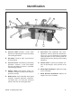
Identification C E D F B A G I H Figure 1. Main view of machine features and controls. A. Crosscut Table—Provides a wide, stable platform for supporting full-size panels during crosscutting operations. F. B. Flip Stops—Used for quick measurements for crosscutting. C. Crosscut Fence—Used during crosscutting operations. Features a scale and multiple flip-style stop blocks for precise, repeatable crosscutting operations. D.
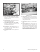
K O L Q M N J P Figure 2. Fence controls. J. Fence Assembly Lock Down Lever— Secures the fence assembly into position along the fence rail. K. Rip Fence Scale—Allows precise measurement of rip cutting operations. L. Forward/Backward Slide Lock Handle— Secures the aluminum fence piece on its forward/backward slide track. M. Micro-Adjust Lock Knob—Secures the fence after it has been adjusted with the micro-adjustment knob. N. Micro-Adjust Knob—Precisely adjusts the fence. -6- Figure 3. Blades. O.
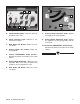
X Y W Z AA R S T U V Figure 4. Control panel close-up. Figure 5. Scoring blade adjustment knobs. R. Power ON/OFF Button—Connects power to all motors in the saw. Y. Scoring Blade Elevation Knob—Adjusts the height of the scoring blade. S. Power Indicator Light—Indicates a live connection to power. Z. T. Main Blade OFF Button—Stops the main saw blade. Scoring Blade Alignment Knob—Adjusts the alignment of the scoring blade and the main blade. U.
SECTION 1: SAFETY For Your Own Safety, Read Instruction Manual Before Operating this Machine The purpose of safety symbols is to attract your attention to possible hazardous conditions. This manual uses a series of symbols and signal words which are intended to convey the level of importance of the safety messages. The progression of symbols is described below. Remember that safety messages by themselves do not eliminate danger and are not a substitute for proper accident prevention measures.
Safety Instructions for Machinery 7. ONLY ALLOW TRAINED AND PROPERLY SUPERVISED PERSONNEL TO OPERATE MACHINERY. Make sure operation instructions are safe and clearly understood. 8. KEEP CHILDREN AND VISITORS AWAY. Keep all children and visitors a safe distance from the work area. 9. MAKE WORKSHOP CHILD PROOF. Use padlocks, master switches, and remove start switch keys. 10. NEVER LEAVE WHEN MACHINE IS RUNNING.
Additional Safety Instructions for Table Saws 1. SAFETY ACCESSORIES. Always use the blade guard and riving knife on all ''throughsawing'' operations. Through-sawing operations are those when the blade cuts completely through the workpiece. 2. KICKBACK. Be familiar with kickback. Kickback happens when the workpiece is thrown towards the operator at a high rate of speed. Until you have a clear understanding of kickback and how it occurs, DO NOT operate this table saw! 3. 7. RIVING KNIFE ALIGNMENT.
Statistics prove that most common accidents among table saw users can be linked to kickback. Kickback is typically defined as the high-speed expulsion of stock from the table saw toward its operator. In addition to the danger of the operator or others in the area being struck by the flying stock, the operator’s hands can be pulled into the blade during the kickback. • Make multiple, shallow passes when performing a non-through cut.
Glossary Of Terms The following is a list of common definitions, terms and phrases used throughout this manual as they relate to this table saw and woodworking in general. Become familiar with these terms for assembling, adjusting or operating this machine. Your safety is VERY important to us at Grizzly! Arbor: Metal shaft extending from the drive mechanism, to which saw blade is mounted. Bevel Edge Cut: Tilting the arbor and saw blade to an angle between 0° and 45° to cut a beveled edge onto a workpiece.
SECTION 2: CIRCUIT REQUIREMENTS 220/440V 3-Phase Serious personal injury could occur if you connect your machine to the power source before you have completed the set up process. DO NOT connect the machine to the power source until instructed to do so.
Phase Converter Rewiring to 440V When using a phase converter, the power from the manufactured power leg (sometimes called the wild wire) can fluctuate. Connect the manufactured power leg to the S terminal to prevent damage to the transformer. The wire from the S terminal can handle some fluctuation because it goes directly to the motor. The power going to the R and T terminals goes to the transformer and must be consistent to prevent damage.
3. At the voltage transformer, pull the fuse that is in the “220” slot and push it into the “440” slot (see Figure 8). 6. Scoring Motor Fuse Turn the dial (Figure 9) on the main motor overload relay to 15A. Main Motor Overload Relay Dial Main Motor Figure 10. Motor locations. Figure 8. Fuse installed at the 220V location. 4. Open the motor cabinet door and remove the motor wiring covers from the main motor and the scoring motor (see Figure 10). 7.
SECTION 3: SET UP Set Up Safety This machine presents serious injury hazards to untrained users. Read through this entire manual to become familiar with the controls and operations before starting the machine! Wear safety glasses during the entire set up process! The Model G0451 is a heavy machine that weighs over 1300 lbs. Serious personal injury may occur if safe moving methods are not followed.
Inventory Box 4: (Figure 13) Qty I. Crosscut Table ........................................... 1 After all the parts have been removed from the boxes, you should have the following items: Box 1: (Figure 11) Qty A. Support Brace ............................................ 1 B. Small Extension Table ................................ 1 C. Large Extension Table ............................... 1 I A C Figure 13. Box 4 contents. B Box 5: (Figure 14) Qty J. Sliding Table End Handle..........................
Box 7: (Figure 15) Qty O. Rip Fence Body .......................................... 1 P. Blade Guard/Dust Hood ............................. 1 Q. Push Stick .................................................. 1 R. Dust Collection Hose Support .................... 1 O Q P R Figure 15. Box 7 contents. Box 7 Cont.: (Figure 16) Qty S. Toolbox ....................................................... 1 — Flat Belt 15 x 787mm ............................. 1 — Riving Knife .........................................
Hardware Recognition Chart G0451 14" Sliding Table Saw -19-
Clean Up The unpainted surfaces are coated with a waxy oil to protect them from corrosion during shipment. Remove this protective coating with a solvent cleaner or citrus-based degreaser such as Grizzly’s G7895 Degreaser. To clean thoroughly, some parts may need to be removed. For optimum performance from your machine, make sure you clean all moving parts or sliding contact surfaces that are coated.
Moving & Placing Base Unit The Model G0451 is a heavy machine that weighs over 1300 lbs. Serious personal injury may occur if safe moving methods are not followed. To be safe, you will need assistance and power equipment when moving the shipping crate and removing the machine from the crate. DO NOT lift the table saw any higher than necessary to clear the floor. Serious personal injury and damage to the machine may occur if safe moving methods are not followed. 3.
Extension Tables 3. Attach the large extension table with four M10-1.5 x 20 cap screws, lock washers, and flat washers as shown in Figure 21. Components and Hardware Needed: Qty Large Extension Table .......................................1 Small Extension Table........................................1 Support Brace ....................................................1 Dust Collection Hose Support ............................1 Cap Screws M10-1.5 x 30 ..................................4 Cap Screws M10-1.
6. Scale Check the surfaces of the table with a straightedge as shown in Figure 23. Components and Hardware Needed: Qty Rip Fence Scale ................................................ 1 Cap Screws M10-1.5 x 20 ..................................4 Hex Nuts M10-1.5 ..............................................2 Lock Washers 10mm ..........................................4 Flat Washers 10mm ...........................................4 Tools Needed: Qty Hex Wrench 8mm .......................................
Rip Fence 5. Components and Hardware Needed: Qty Rip Fence .......................................................... 1 Rip Fence Round Rail ....................................... 1 Rip Fence Body ................................................. 1 Stud M12-1.75 x 115 .......................................... 4 Hex Nut M12-1.75 ............................................ 12 Flat Washer 12mm ............................................ 8 Lock Washer 12mm ...........................................
8. Slide the aluminum rip fence onto the clamping plate as shown in Figure 29 and lock it with the handle on top of the rip fence body. 11. Adjust the height of the rip fence rail, then tighten all of the nuts against the table as shown in Figure 31. Clamping Plate Figure 29. Installing the rip fence. 9. Adjust the nuts on the outside of the table until the edge of the rip fence is parallel with the sliding table as shown in Figure 30.
Crosscut Table 2. Components and Hardware Needed: Qty Crosscut Table ...................................................1 Crosscut Table Brace .........................................1 T-Nut M8-1.25 .....................................................2 T-Nut M12-1.75....................................................1 Flat Washer 12mm .............................................1 Adjustable Handle M12-1.75 x 55 .......................1 Knob M8-1.25 x 50 .............................................
Crosscut Fence 4. Components and Hardware Needed: Qty Crosscut Fence ..................................................1 Center Stud M8-1.25 x 10 ..................................1 Fiber Washer 8mm .............................................1 T-Nut M8-1.25 .....................................................1 Knob M8-1.25 x 25 .............................................1 Knob M8-1.25 .....................................................1 T-Bolt M8-1.25 x 60 ..........................................
Sliding Table 2. Install the lock plate as shown in Figure 40 using 4 of the screws removed in the previous step. Components and Hardware Needed: QTY T-Nut M12-1.75....................................................1 Flat Washer 12mm .............................................1 Push Handle M12-1.75 x 12 ................................1 Edge Shoe ..........................................................1 Hold Down ..........................................................1 Sliding Table End Handle ..
5. Main Blade Slide the M12-1.75 T-nut into the sliding table and thread in the M12-1.75 x 12 push handle with a washer as shown in Figure 42. The Model G0451 is designed to accommodate either a 12" or a 14" main blade. But any time you change blade sizes, the riving knife must be adjusted to match the size of blade you install. Push Handle Components and Hardware Needed: Qty Blade 12" or 14" (Not Included) .........................1 Flat Belt 15 x 915mm .........................................
4. Slide the table all the way forward to access the blade arbor and pull open the blade guard (see Figure 45). 8. Loosen the riving knife center bolt, slide the riving knife over the bolt as shown in Figure 47, and slightly tighten. Riving Knife Main Blade Arbor Figure 47. Installing the riving knife. Figure 45. Main blade arbor components. 5. Use the arbor wrench to remove the arbor nut and arbor flange. Note—The arbor nut has left hand threads and loosens by turning clockwise. 6.
Aligning Scoring Blade Set To align the scoring blade set: 1. Move the blade tilt to 0˚ (blade 90˚ to table), raise the main blade all the way up, and use the vertical adjustment knob (Figure 49) to raise the scoring blade to its highest point. Scoring Blade Vertical Adjustment Adjusting Scoring Blade Kerf The kerf of the tapered scoring blade included with this sliding table saw is adjusted by changing the height of the scoring blade. See Page 37 for replacement scoring blade adjusting instructions.
Dust Collection 3. The Model G0451 is equipped with two dust ports that should be properly connected to a dust collection system before operation. Slide the blade guard/dust hood over the riving knife and attach it with an M8-1.25 x 40 button head cap screw and a flat washer as shown in Figure 52. Components and Hardware Needed: Qty Blade Guard/Dust Hood .....................................1 Flat Washer 8mm ...............................................1 Button Head Screw M8-1.25 x 40 ................
Power Cord Test Run Before installing the power cord, read through Section 2: Circuit Requirements to check that your setup follows the safety and circuit requirements, and the power cord and plug that you have chosen meet the requirements for this machine. Now that the machine is connected to the power source, it is important to perform a test run to make sure all the controls are working properly. Components and Hardware Needed: Qty Power Cord ........................................................
SECTION 4: OPERATIONS Operation Safety Operation Tips Damage to your eyes, lungs, and ears could result from using this machine without proper protective gear. Always wear safety glasses, a respirator, and hearing protection when operating this machine. Your safety is important. The tips below are intended to supplement Section 1: Safety. But remember, no safety list can be comprehensive of every situation. The operator is ultimately responsible for their own safety, as well as the safety of bystanders.
Changing Main Blade The Model G0451 will perform best when high quality, sharp blades are used. Therefore, whenever the main blade starts to get dull, we recommend that you have it resharpened or replace it with a new blade. 5. Use the arbor wrench to remove the arbor nut and arbor flange and pull the old blade off the arbor. Note—The arbor nut has left hand threads and loosens by turning clockwise. 6. Slide the new blade over the arbor with the teeth facing the front of the saw as shown in Figure 56.
Riving Knife Adjustment 6. Whenever the blade size is changed (12" or 14" blade), the riving knife must be adjusted to 3mm away from the blade you install. Position the riving knife about 3mm or 1⁄8" away from the nearest carbide tooth on the main blade. Note—For a quick gauge, use the 3mm hex wrench to find the correct spacing between the blade and the riving knife, as shown in Figure 58. To adjust the riving knife: 1. Disconnect the saw from the power source! 2.
Adjusting and Replacing Scoring Blade 4. To remove the scoring blade, use the arbor wrench to remove the arbor nut and arbor flange (see Figure 60). Note—The arbor nut has right-hand threads and loosens by turning counterclockwise. The scoring blade that is included with the sliding table saw is wedge shaped. The kerf thickness of this style of scoring blade is adjusted by changing the height of the scoring blade.
Rip Cutting Determine which cutting operation will be best suited for the workpiece to be ripped. —To use the sliding table, read the instructions titled “Rip cutting with the sliding table.” The Model G0451 has the capability of rip cutting full size panels (Figure 61). The sliding table removes the burden of sliding a large and heavy panel over a stationary table surface. —To use the machine as a traditional table saw, skip ahead to “Rip cutting using the traditional table saw technique.
Rip cutting using the traditional table saw technique: 1. Slide the crosscut table out of the way. 2. Lock the sliding table into a stationary position (see Figure 64). 4. Slide the leading end of the rip fence so it is even with the center of the main saw blade as shown in Figure 66. Note—This technique allows the finished cut-off piece to “fall” away from the blade when the cutting operation is complete; reducing the possibility of kickback. Table Lock Figure 64. Sliding table lock. 3.
Crosscutting Lastly, this machine has the capability of crosscutting workpieces while using the rip fence as a cut-off gauge (Figure 70). The Model G0451 can crosscut full size panels with the fence in the forward or rear position, although it is easier to load full size panels with the crosscut fence mounted in the forward position (see Figure 68). Forward Mounted Crosscut Fence Figure 70. Crosscutting workpieces using the rip fence as a cut-off gauge.
Crosscutting full size panels: 1. 2. Install the crosscut fence in the forward mounting points shown in Figure 71 and lock it in place. Check to make sure the fence is at 90˚ and adjust it as described in "Squaring Crosscut Fence to Blade" on Page 52 if necessary. Rear Mounting Points Forward Mounting Points 4. Load the workpiece onto the table saw. The set up should look similar to Figure 69. 5. Once all the necessary safety precautions have been taken, perform the cutting operation.
Miter Cutting The miter fence allows miter cuts from 0˚ through 135˚. The table mounted miter scale has a resolution of 1˚. To perform a miter cut: 1. Slide the crosscut table to the front edge of the sliding table and lock it in place. 2. Place the crosscut fence center stud in the center stud hole of the crosscut table. The fence can be installed as shown in Figure 73 for 90˚ to 135˚ cuts, or as shown in Figure 74 for 0˚ to 90˚ cuts. 3.
SECTION 5: ACCESSORIES G7895—Citrus Degreaser This citrus based degreaser is perfect for cleaning cosmoline off of new equipment. It also works for cleaning auto parts, tools, concrete, and porcelain surfaces. Natural, safe for the environment, and contains no CFC’s. G5562—SLIPIT® 1 Qt. Gel G5563—SLIPIT® 12 oz Spray Used on cast iron table surfaces and other unpainted metal surfaces to reduce sliding friction and hangups. This product also reduces rust and prevents resin build-up. Figure 75.
G7984—Face Shield H1298—Dust Sealed Safety Glasses H1300—UV Blocking, Clear Safety Glasses H2347—Uvex® Spitfire Safety Glasses H0736—Shop Fox® Safety Glasses Safety Glasses are essential to every shop. If you already have a pair, buy extras for visitors or employees. You can't be too careful when it comes to shop safety! H1300 H3388—14" Carbide Tipped Saw Blade, 80T H3389—14" Carbide Tipped Saw Blade, 100T These blades are designed especially for sliding table saws and manufactured for heavy-duty use.
H3308—SHOP FOX® Push Stick Measuring 131⁄2" overall, this push stick allows the operator to keep their hands at a safe distance away from the blade or cutter. H3771—Blade Loc® This simple tool secures the blade during blade changes, keeping your hands safe and your expensive blade from being damaged. Figure 83. H3308 SHOP FOX® Push Stick. Figure 85. H3771 Blade Loc®.
SECTION 6: MAINTENANCE Cleaning Always disconnect power to the machine before performing maintenance. Failure to do this may result in serious personal injury. Schedule For optimum performance from your machine, follow this maintenance schedule and refer to any specific instructions given in this section. Daily Check: • Loose mounting bolts. • Worn or damaged saw blade. • Worn or damaged switches or wires. • Any other unsafe condition. Weekly Maintenance: • Clean sliding table surface and grooves.
Lubrication 3. Scoring blade worm gears. Lubricate with an automotive wheel bearing grease. Blade Height Slide The bearings are sealed and pre-lubricated and require no lubrication during their usable life. However, your saw components will operate at their best if the bearing surfaces are kept clean—this is especially important for the trunnion bearings. Lubricate the areas indicated below every 6-12 months, depending on frequency of use. 1. Blade Height Linkage Blade angling trunnions.
Maintenance Log Date -48- Approximate Hours Of Use Maintenance Performed G0451 14" Sliding Table Saw
SECTION 7: SERVICE Replacing Belts Always disconnect power to the machine before performing service adjustments. Failure to do this may result in serious personal injury. To change the V-belt on the main motor: 1. Disconnect the saw from the power source! 2. Move the blade tilt to 0˚ (blade 90˚ to table), and raise the main blade and scoring blade set up as far as they will go. 3. Open the motor cabinet door. 4. Loosen the tension bolt (Figure 90) and pivot the motor up to remove the V-belts.
To change the belt on the scoring blade motor: 1. Disconnect the saw from the power source! 2. Move the blade tilt to 0˚ (blade 90˚ to table), and raise the main blade and scoring blade set up as far as they will go. 3. Open the motor cabinet door. 4. Push the scoring blade motor and remove the flat belt. 5. Place the flat belt on the scoring blade arbor as shown in Figure 91, lift the scoring motor, and slide the flat belt over the scoring motor pulley. 2.
Sliding Table Parallel Adjustment 5. Rotate the blade 180° and slide the table with the measuring device to position B. 6. Measure the difference between the two positions (use the feeler gauge if using the adjustable square). Make note of the difference between the two measurements on a piece of paper. The table is calibrated at the factory, but can be adjusted if it changes during the life of the machine.
9. Slowly make the adjustments to the parallelism adjustment bolts (Figure 95) on the end that is closer to the blade. 3. Use the crosscut fence to cut 1⁄2" off of each side of the test piece, then cut side 1 again (make five cuts total). 4. Measure the test piece diagonally from corner-to-corner as shown in Figure 96. — If both measurements are not within 1⁄16", then the crosscut fence needs to be adjusted. Proceed to Step 6.
Service Log Date Approximate Hours Of Use G0451 14" Sliding Table Saw Maintenance Performed -53-
Troubleshooting Symptom Motor will not start, or it growls on start up. Possible Cause Possible Solution 1. Emergency stop button is depressed. 2. Power supply fuse or circuit breaker has tripped. 3. Thermal overload has tripped. 4. Toggle switch is broken inside. 5. Start capacitor is at fault. 6. Motor fan cover is dented, stopping the fan from being able to spin. 7. Motor is at fault. 1. Rotate the button clockwise and allow it to pop out. 2.
Symptom Possible Cause Possible Solution Loud repetitious noise coming 1. Pulley setscrews or keys are missing 1. Inspect keys and setscrews. Replace from machine. or loose. or tighten if necessary. 2. Motor fan is hitting the cover. 2. Adjust fan cover mounting position, tighten fan, or shim fan cover. 3. V-belts are defective or damaged. 3. Replace V-belts (Page 49). Vibration when running or cut- 1. Loose or damaged blade. ting. 2. Worn arbor bearings. 3. Worn or damaged belts. 1.
Electrical REF PART # DESCRIPTION REF PART # DESCRIPTION 1 P04510001 Key Switch 4 P04510004 Switch Button-OFF 2 P04510002 Power Lamp 5 P04510005 Emergency Stop Button 3 P04510003 Switch Button-ON 5 3 3 2 1 4 4 3 1 3 5 2 4 4 �������������������� ������������������ ���������������� �� �� �� �� �� �� �� �� �� �� �� �� �� �� �� �� �� �� �� �� �� �� �� �� ���� -56- ���� �� �� �� �� �� �� �� �� �� �� �� �� �� �� �� �� �� �� ���� ���� G04
REF PART # DESCRIPTION REF PART # DESCRIPTION 6 P04510006 Terminal 3 Circuit 12 P04510012 Over Load RA-30 (15~30A) 7 P04510007 Terminal 6 Circuit 13 P04510013 Magnetic Contactor MA-09 8 P04510008 Fuse Base 14 P04510014 Over Load RA-15 for 220V 9 P04510009 Fuse 250V 10A 14A P04510014A Over Load RA-15 for 440V 10 P04510010 Transformer 15 P04510015 11 P04510011 Magnetic Contactor MA-30 2 5 1 � � � 6 �� �� �� 5 15 4 ���� �� �� �� �� � � �� �� �� �� 4 ����� ��
-58- ��� ��� ��� ��� ��� ��� ��� ��� ��� ��� ��� ��� ��� ��� ��� ��� ��� ��� ��� ��� ��� ��� ��� ��� SECTION 8: PARTS Extension Arm Assembly G0451 14" Sliding Table Saw
REF PART # DESCRIPTION REF PART # DESCRIPTION 101 P04510101 T-NUT M8-1.25 113 PLW04M LOCK WASHER 8MM 102 P04510102 STOP BRACKET 114 P04510114 LOCATE PLATE 103 P04510103 KNOB M8-1.25 X 40 115 P04510115 KNOB SCREW M8-1.25 X 25 104 P04510104 STUD M10-1.5 X 70 116 P04510116 SQUARE FENCE 105 P04510105 FLIP STOP 117 P04510117 CNTR STUD M8-1.25 X 10 106 PSS01M SET SCREW M6-1 X 10 118 P04510118 FIBER WASHER 10 X 18 107 PLN05M LOCK NUT M10-1.5 119 P04510101 T-NUT M8-1.
��� ��� ��� ��� -60- ��� ��� ��� ��� ��� ��� ��� ��� ��� ��� ��� ��� ��� ��� ��� ��� ��� ��� ��� ��� ��� ��� ��� ��� ��� ��� ��� ��� ��� Extension Table Assembly G0451 14" Sliding Table Saw
REF PART # DESCRIPTION REF PART # DESCRIPTION 201 P04510201 ROLLER 218 PSB115M BTN HD CAP SCR M6-1 X 16 202 PSS01M SET SCREW M6-1 X 10 219 PLW03M LOCK WASHER 6MM 203 P04510203 ECCENTRIC 220 P04510220 PAD 204 P04510204 PLUG 80 X 40 221 P04510221 FENDER WASHER 12MM 205 P04510205 SUPPORT FRAME 222 P04510208 FENDER WASHER 8MM 206 P04510101 T-NUT M8-1.25 223 P04510223 KNOB M8-1.25 X 50 207 P04510207 KNOB M8-1.
-62- ��� ��� ��� ��� ��� ��� ��� ��� ��� ��� ��� ��� ��� ��� ��� ��� ��� ��� ��� ��� ��� ��� ��� ��� ��� ��� ��� ��� ��� ��� ��� �� �� ��� ��� ��� ��� ��� ��� ��� ��� ��� ��� ��� ��� ��� ��� ��� ��� ��� ��� ��� ��� ��� ��� ��� ��� ��� ��� ��� ��� ��� �� �� �� ��� ��� ��� ��� Base Assembly G0451 14" Sliding Table Saw
REF PART # DESCRIPTION REF PART # DESCRIPTION 301 PSB50M CAP SCREW M5-.8 X 10 342 PSS84M SET SCREW M10-1.5 X 35 302 P04510302 FENDER WASHER 5MM 343 PN09M HEX NUT M12-1.75 303 PS09M PHLP HD SCR M5-.8 X 10 344 PB33M HEX BOLT M12-1.75 X 50 304 P04510304 POINTER 345 PN03M HEX NUT M8-1.25 305 P04510305 FIX PLATE 346 PB26M HEX BOLT M8-1.
��� ��� -64- ��� ��� ��� ��� ��� ��� ��� ��� ��� ��� ��� ��� ��� ��� ��� ��� ��� ��� ��� ��� ��� ��� ��� ��� ��� ��� ��� ��� ��� ��� ��� ��� ��� ��� ��� ��� ��� ��� ��� ��� ��� ��� ��� ��� ��� ��� ��� ��� ��� ��� ��� ��� ��� ��� ��� ��� Blade Assembly G0451 14" Sliding Table Saw
REF PART # DESCRIPTION REF PART # DESCRIPTION 401 PW04M FLAT WASHER 10MM 432 PLW01M LOCK WASHER 5MM 402 PRP58M ROLL PIN 6 X 45 433 PW02M FLAT WASHER 5MM 403 PLW06M LOCK WASHER 10MM 434 P04510434 FIX BLOCK 404 PSB84M CAP SCREW M10-1.5 X 35 435 P04510208 FENDER WASHER 8MM 405 P04510405 LEFT TRUNNION BRACKET 436 PLW04M LOCK WASHER 8MM 406 P04510406 LOCATE PLATE 437 PSB31M CAP SCREW M8-1.
-66- ��� ��� ��� ��� ��� ��� ��� ��� ��� ��� ��� ��� ��� ��� ��� ��� ��� ��� ��� ��� ��� ��� ��� ��� ��� ��� ��� ��� ��� ��� ��� ��� ��� ��� ��� ��� Arbor and Dust Hood Assembly G0451 14" Sliding Table Saw
REF PART # DESCRIPTION REF PART # DESCRIPTION 501 P04510501 BLADE GUARD 520 P04510208 FENDER WASHER 8MM 502 P04510208 FENDER WASHER 8MM 521 P04510521 BUSHING 503 PSBS07M BTN HD SCR M8-1.25 X 40 522 P04510522 LINK PLATE 504 PN09M HEX NUT M12-1.
��� ��� ��� -68- ��� ��� ��� ��� ��� ��� ��� ��� ��� ��� ��� ��� ��� ��� ��� ��� ��� ��� ��� ��� ��� ��� ��� ��� ��� ��� ��� ��� ��� ��� ��� ��� ��� ��� ��� ��� ��� ��� ��� ��� ��� ��� ��� ��� ��� ��� ��� ��� ��� ��� ��� ��� ��� ��� Sliding Table Assembly G0451 14" Sliding Table Saw
REF PART # DESCRIPTION REF PART # DESCRIPTION 601 P04510601 LOCATE PLATE 630 P04510630 BLOCK 602 PSB115M BTN HD CAP SCR M6-1 X 16 631 P04510631 DISC-GASKET 603 P04510603 PROTECT PLATE 632 P04510215 T-NUT M12-1.75 604 P04510604 T-BOLT M12-1.75 X 60 633 P04510633 PIN LOCK 605 PW06M FLAT WASHER 12MM 634 PN05M HEX NUT M16-1.5 606 PLW05M LOCK WASHER 12MM 635 PSB11M CAP SCREW M8-1.25 X 16 607 PN09M HEX NUT M12-1.
-70- ��� ��� ��� ��� ��� ��� ��� ��� ��� ��� ��� ��� ��� ��� ��� ��� ��� ��� ��� ��� ��� ��� ��� ��� ��� ��� ��� ��� ��� ��� ��� ��� ��� ��� ��� ��� ��� ��� ��� ��� Table Assembly G0451 14" Sliding Table Saw
REF PART # DESCRIPTION REF PART # DESCRIPTION 701 P04510701 SUPPORT BRACE 721 PSS04M SET SCREW M6-1 X 12 702 PN03M HEX NUT M8-1.25 722 PN02M HEX NUT M10-1.5 703 PSB14M CAP SCREW M8-1.25 X 20 723 P04510723 SCALE 704 PSB11M CAP SCREW M8-1.25 X 16 724 PLW06M LOCK WASHER 10MM 705 PLW04M LOCK WASHER 8MM 725 PSB64M CAP SCREW M10-1.5 X 20 706 P04510208 FENDER WASHER 8MM 726 P04510726 STUD M12-1.75 X 115 707 PSB61M CAP SCREW M10-1.5 X 20 727 PN09M HEX NUT M12-1.
��� ��� -72��� ��� ��� ��� ��� ��� ��� ��� ��� ��� ��� ��� ��� ��� ��� ��� ��� ��� ��� ��� ��� ��� ��� ��� ��� ��� ��� ��� ��� ��� ��� Fence Assembly G0451 14" Sliding Table Saw
REF PART # DESCRIPTION REF PART # DESCRIPTION 801 P04510801 ROTATE SHAFT 818 PSB115M BTN HD CAP SCR M6-1 X 16 802 P04510802 HANDLE M10-1.5 X 12 819 PSBS09M BTN HD CAP SCR M6-1 X 12 803 P04510803 RIP FENCE HOUSING 820 PW03M FLAT WASHER 6MM 804 P04510804 KNOB M10-1.5 X 70 821 P04510821 PLATE 805 PN03M HEX NUT M8-1.25 822 P04510822 COMPRESSION SPRING 806 P04510806 LOCATE PLATE 823 P04510823 CAM 807 P04510807 MICRO-ADJUST KNOB 824 PSB11M CAP SCREW M8-1.
-74- ��� ��� ��� ��� ��� ��� ��� ��� ��� ��� ��� ��� ��� ��� ��� ��� ��� ��� ��� ��� ��� ��� ��� ��� ��� ��� ��� ��� ��� ��� ��� ��� ��� ��� ��� ��� ��� ��� ��� ��� ��� ��� ��� ��� ��� ��� ��� ��� ��� ��� ��� ��� ��� ��� ��� ����� ����� ��� ����� ��� ��� ��� ��� �� ��� ��� ��� �� �� �� �� Motor Assembly G0451 14" Sliding Table Saw
REF PART # DESCRIPTION REF PART # DESCRIPTION 901 PN09M HEX NUT M12-1.75 937 PB100M HEX BOLT M14-2 X 100 902 P04510902 SCORING FLANGE 938 PSB37M CAP SCREW M6-1 X 50 903 P04510903 SCORING BLADE 22MM 939 P04510939 FIX PLATE 904 P04510904 SCORING ARBOR 22MM 940 PSB60M CAP SCREW M8-1.25 X 55 905 PLN04M LOCK NUT M8-1.
-76���� ���� ���� ���� ���� ���� ���� ���� ���� ���� ���� ���� ���� ���� ���� ���� ���� ���� ���� ���� ���� ���� ���� ���� ���� ���� ���� ���� ���� ���� ���� ���� ���� ���� ���� ���� ���� ���� ���� ���� ���� ���� ���� ���� ���� Blade Adjustment Assembly G0451 14" Sliding Table Saw
REF PART # DESCRIPTION REF PART # DESCRIPTION 1001 PSB04M CAP SCREW M6-1 X 10 1024 P04511024 BALL BEARING UCFK205 1002 P04511002 FREE JOINT 1025 PSB11M CAP SCREW M8-1.25 X 16 1003 PSB04M CAP SCREW M6-1 X 10 1026 PLW04M LOCK WASHER 8MM 1004 PR05M EXT RETAINING RING 15MM 1027 P0451208 FENDER WASHER 8MM 1005 PSB11M CAP SCREW M8-1.25 X 16 1028 PR05M EXT RETAINING RING 15MM 1006 PLW04M LOCK WASHER 8MM 1029 PSB03M CAP SCREW M5-.
-78- ���� ���� ���� ���� ���� ���� ���� ���� ���� ���� ���� ���� ���� ���� ���� ���� ���� ���� ���� ���� ���� ���� ���� ���� ���� ���� ���� ���� ���� Swing Arm Assembly G0451 14" Sliding Table Saw
REF PART # DESCRIPTION REF PART # DESCRIPTION 1101 P04511101 NYLON WASHER M10 X 25 1116 PSS19M SET SCREW M8-1.25 X 30 1102 P04511102 SUPPORT SHAFT 1117 P04511117 ROLLER 1103 PN05M HEX NUT M16-1.5 1118 P6202 BALL BEARING 6202ZZ 1104 P04511104 PLUG 100 X 50 1119 PSS19M SET SCREW M8-1.25 X 30 1105 PB26M HEX BOLT M8-1.
-80- ���� ���� ���� ���� ���� ���� ���� ���� ���� ���� ���� ���� ���� ���� ���� ���� ���� ���� ���� ���� ���� ���� ���� ���� ���� ���� ���� ���� ���� ���� ���� ���� ���� ���� ���� ���� ������ ���� ���� ���� ������ ������ ���� ���� ���� ���� ���� ���� ���� ���� Main Motor Assembly G0451 14" Sliding Table Saw
REF PART # DESCRIPTION REF PART # DESCRIPTION 1201 P04511201 DUST PORT 1226 PLW06M LOCK WASHER 10MM 1202 PSB52M CAP SCREW M8-1.25 X 10 1227 PW04M FLAT WASHER 10MM 1203 PLW04M LOCK WASHER 8MM 1228 P04511228 MAIN MOTOR 10HP 1204 P04511204 ROTATE PLATE 1228-1 P04511228-1 FAN COVER 1205 PSS01M SET SCREW M6-1 X 10 1228-2 P04511228-2 MOTOR FAN 1206 P04511206 SHAFT 1228-3 P04511228-3 MOTOR WIRING BOX 1207 P04511207 LOCATE PLATE 1229 PN02M HEX NUT M10-1.5 1208 PN09M HEX NUT M12-1.
WARRANTY AND RETURNS Grizzly Industrial, Inc. warrants every product it sells for a period of 1 year to the original purchaser from the date of purchase. This warranty does not apply to defects due directly or indirectly to misuse, abuse, negligence, accidents, repairs or alterations or lack of maintenance.
WARRANTY CARD Name _____________________________________________________________________________ Street _____________________________________________________________________________ City _______________________ State _________________________ Zip _____________________ Phone # ____________________ Email ________________________ Invoice # _________________ Model # ____________________ Order # _______________________ Serial # __________________ The following information is given on a voluntary basis.
FOLD ALONG DOTTED LINE Place Stamp Here GRIZZLY INDUSTRIAL, INC. P.O.
����������������������������������������������������������������������� ������������������������������������� ������������������������������������ ����������������� �������������������������������� ��������������������������������� ���� ��������������������� ������������������