MODEL G0453/G0454 15" & 20" MOBILE PLANERS OWNER'S Manual Copyright © MAY, 2005 By Grizzly Industrial, Inc., REVISED MAY, 2011 (TS) Warning: No portion of this manual may be reproduced in any shape Or form without the written approval of Grizzly Industrial, inc.
This manual provides critical safety instructions on the proper setup, operation, maintenance, and service of this machine/tool. Save this document, refer to it often, and use it to instruct other operators. Failure to read, understand and follow the instructions in this manual may result in fire or serious personal injury—including amputation, electrocution, or death. The owner of this machine/tool is solely responsible for its safe use.
Table of Contents INTRODUCTION................................................ 2 Manual Accuracy............................................ 2 Contact Info.................................................... 2 Machine Description....................................... 2 Identification.................................................... 3 Internal Components...................................... 4 G0453 Machine Data Sheet........................... 5 G0454 Machine Data Sheet...........................
INTRODUCTION Manual Accuracy Contact Info We are proud to offer this manual with your new machine! We've made every effort to be exact with the instructions, specifications, drawings, and photographs of the machine we used when writing this manual. However, sometimes we still make an occasional mistake. We stand behind our machines. If you have any questions or need help, use the information below to contact us. Before contacting, please get the serial number and manufacture date of your machine.
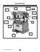
Identification Return Rollers Magnetic ON/OFF Switch Table Height Handwheel Gearbox Rear Extension Wing Feed Rate Control Knob V-Belt Cover Bed Rollers Front Extension Wing Table Locks Lifting Bar (1 of 4) Cabinet Access Panel Locking Foot Pedal Figure 1. General identification. G0453/G0454 (Mfg.
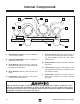
Internal Components D C A F E B G Workpiece H I H Figure 2. Workpiece path and major planing components (side cutaway view). A. Anti-Kickback Fingers: Provide additional safety for the operator. B. Serrated Infeed Roller: Pulls the workpiece toward the cutterhead. C. Chip Breaker: Breaks off chips created by the cutterhead to prevent tear out and diverts the chips to the dust port. D. Chip Deflector: Directs chips into the dust hood. E.
G0453 Machine Data Sheet MACHINE DATA SHEET Customer Service #: (570) 546-9663 · To Order Call: (800) 523-4777 · Fax #: (800) 438-5901 MODEL G0453 15" PLANER data sheet Product Dimensions: Weight.............................................................................................................................................................. 655 lbs. Width (side-to-side) x Depth (front-to-back) x Height............................................................... 32-1/2 x 42 x 45-7/8 in.
Cutterhead Info Cutterhead Type...................................................................................................................................... 3 Knife Cutterhead Dia............................................................................................................................................. 3 in. No. of Knives.................................................................................................................................................... 3 Knife Type..
G0454 Machine Data Sheet MACHINE DATA SHEET Customer Service #: (570) 546-9663 · To Order Call: (800) 523-4777 · Fax #: (800) 438-5901 MODEL G0454 20" PLANER Product Dimensions: Weight.............................................................................................................................................................. 890 lbs. Width (side-to-side) x Depth (front-to-back) x Height........................................................ 39-1/2 x 55-1/2 x 45-7/8 in.
Cutterhead Info Cutterhead Type...................................................................................................................................... 4 Knife Cutterhead Dia...................................................................................................................................... 3-1/8 in. No. of Knives.................................................................................................................................................... 4 Knife Type.....
SECTION 1: SAFETY For Your Own Safety, Read Instruction Manual Before Operating this Machine The purpose of safety symbols is to attract your attention to possible hazardous conditions. This manual uses a series of symbols and signal words intended to convey the level of importance of the safety messages. The progression of symbols is described below. Remember that safety messages by themselves do not eliminate danger and are not a substitute for proper accident prevention measures.
DISCONNECTING POWER SUPPLY.Alwaysdisconnect machine from power supply before servicing, adjusting, or changing cutting tools (bits, blades, cutters, etc.). Make sure switch is in OFF positionbeforereconnectingtoavoidanunexpectedorunintentionalstart. APPROVED OPERATION. Untrained operators can be seriously hurt by machinery. Only allow trained or properly supervised people to use machine.
Additional Safety Instructions for Planers OWNER'S MANUAL. This machine presents significant safety hazards to untrained users. Read and understand this entire manual before starting the planer. KICKBACK. Be familiar with kickback. Kickback happens when the workpiece is thrown towards the operator at a high rate of speed. Until you have a clear understanding of kickback and how it occurs, DO NOT operate this planer! REACHING INSIDE PLANER.
SECTION 2: POWER SUPPLY Availability G0453 220V Circuit Requirements Before installing the machine, consider the availability and proximity of the required power supply circuit. If an existing circuit does not meet the requirements for this machine, a new circuit must be installed. To minimize the risk of electrocution, fire, or equipment damage, installation work and electrical wiring must be done by a qualified electrician in accordance with all applicable codes and standards.
Grounding Instructions This machine MUST be grounded. In the event of certain malfunctions or breakdowns, grounding reduces the risk of electric shock by providing a path of least resistance for electric current. The plug specified under "Circuit Requirements" on the previous page has a grounding prong that must be attached to the equipment-grounding wire on the included power cord.
SECTION 3: SETUP Needed for Setup This machine presents serious injury hazards to untrained users. Read through this entire manual to become familiar with the controls and operations before starting the machine! Wear safety glasses during the entire setup process! The following are needed to complete the setup process, but are not included with your machine: Description Qty • Assistant...................................................... 1 • Safety Glasses.........................
Inventory The following is a description of the main components shipped with your machine. Lay the components out to inventory them. If any non-proprietary parts are missing (e.g. a nut or a washer), we will gladly replace them; or for the sake of expediency, replacements can be obtained at your local hardware store. Box Inventory: (Figure 5) Qty A. Planer (Not Shown)..................................... 1 B. Dust Hood................................................... 1 C. Foot Pedal.......................
Cleanup The unpainted surfaces of your machine are coated with a heavy-duty rust preventative that prevents corrosion during shipment and storage. This rust preventative works extremely well, but it will take a little time to clean. Be patient and do a thorough job cleaning your machine. The time you spend doing this now will give you a better appreciation for the proper care of your machine's unpainted surfaces.
Site Considerations Weight Load Physical Environment Refer to the Machine Data Sheet for the weight of your machine. Make sure that the surface upon which the machine is placed will bear the weight of the machine, additional equipment that may be installed on the machine, and the heaviest workpiece that will be used. Additionally, consider the weight of the operator and any dynamic loading that may occur when operating the machine.
assembly Lifting & Moving Base Unit Assembly To assemble your planer: 1. Install M8-1.25 x 20 set screws in the holes in the bottom of the wings (see Figure 8). The Model G0453/G0454 is a heavy machine. Serious personal injury may occur if safe moving methods are not used. To be safe, get assistance and use power equipment to move the shipping crate and remove the machine from the crate.
4. Place the bushing on the handwheel shaft. 5. Insert the key into the shaft keyway. 6. Screw the handle into the handwheel. 7. Place the handwheel on the shaft and secure it with the M12-1.75 hex nut and 12mm flat washer, as shown in Figure 9. Figure 9. Installing the table height handwheel. 8.
12. Using the short end of a clean hex wrench, dip it inside the fill hole and remove it. —If the end of the hex wrench is coated with oil, then the gearbox oil level is okay. Replace the fill plug and skip to the next section. —If the end of the hex wrench is not coated with oil, then you need to add more oil. Refer to Page 32 for instructions on how to do this. NOTICE Replace the gearbox oil after the first 20 hours of operation. This is a normal breakin procedure. 15.
Dust Collection DO NOT operate the Model G0453/G0454 without an adequate dust collection system. This planer creates substantial amounts of wood dust while operating. Failure to use a dust collection system can result in short and long-term respiratory illness. Recommended CFM at Dust Port • G0453...........................................400 CFM • G0454...........................................625 CFM Do not confuse this CFM recommendation with the rating of the dust collector.
4. Push the OFF button in, then twist it clockwise so it pops out. When the OFF button pops out, the switch is reset and ready for operation (see Figure 14). Re-Tension V-Belts The final step of the setup process must be done after approximately 16 hours of operation. During this period, the V-belts will stretch and seat into the pulley grooves and need to be properly tensioned to avoid severely reducing the life of the V-belts. Refer to V-Belts on Page 37 for detailed instructions.
SECTION 4: OPERATIONS Operation Overview To reduce the risk of serious injury when using this machine, read and understand this entire manual before beginning any operations. The purpose of this overview is to provide the novice machine operator with a basic understanding of how the machine is used during operation, so the machine controls/components discussed later in this manual are easier to understand.
Planing Tips • Use the full width of the planer. Alternate between the left, the right and the middle of the table when feeding lumber into the planer. Your knives will remain sharp much longer. • Scrape all glue off of joined boards before planing. Dried glue is extremely hard on the knives. • Plane ONLY natural wood fiber. Do not plane wood composites or other materials that could break up in the planer and cause operator injury or property damage.
Wood Hardness Feed Rate The species of wood, as well as its condition, greatly affects the depth of cut the planer can effectively take with each pass. The infeed and outfeed rollers move the workpiece through the planer while keeping it flat and providing a consistent rate of movement. The speed that these rollers move the workpiece through the planer is known as the feed rate. The chart in the figure below shows the Janka Hardness Rating for a number of commonly used species.
Depth of Cut Bed Roller Height The depth of cut on a planer means the amount of material that is removed from the top of the workpiece as it passes underneath the cutterhead. Bed Roller Height Range...............0.002"–0.020" The depth of cut is set by adjusting the distance of the table below the cutterhead. This distance is the thickness of the workpiece minus the depth of cut. The correct height of the bed rollers will vary, depending on the type of material you intend to plane.
NOTICE Bed rollers that are not adjusted to the correct height or out of alignment with each other can cause poor finishes, inconsistent planing thickness, and other undesirable results. Tools Needed Qty Hex Wrench 3mm............................................... 1 Wrench 14mm.................................................... 1 Rotacator............................................................ 1 4.
ACCESSORIES SECTION 5: ACCESSORIES Some aftermarket accessories can be installed on this machine that could cause it to function improperly, increasing the risk of serious personal injury. To minimize this risk, only install accessories recommended for this machine by Grizzly. NOTICE Refer to the newest copy of the Grizzly Catalog for other accessories available for this machine.
T20501—Face Shield Crown Protector 4" T20502—Face Shield Crown Protector 7" T20503—Face Shield Window T20448—Economy Clear Safety Glasses T20452—"Kirova" Anti-Reflective Glasses T20456—"Dakura" Clear Safety Glasses H0736—Shop Fox® Safety Glasses These glasses meet ANSI Z87.1-2003 specifications. Buy extras for visitors or employees.
SECTION 6: MAINTENANCE Always disconnect power to the machine before performing maintenance. Failure to do this may result in serious personal injury. Schedule For optimum performance from your machine, follow this maintenance schedule and refer to any specific instructions given in this section. Note: This maintenance schedule is based on average daily usage. Adjust the maintenance schedule to match your usage to keep your planer running smoothly and to protect your investment.
Lubrication NOTICE Failure to followed reasonable lubrication practices as instructed in this manual for your lathe could lead to premature failure of your lathe and will void the warranty. Columns and Leadscrews The table rides on the columns and is moved by the rotation of the leadscrews inside the columns. Loosen the dust sleeve (see Figure 28) to access the columns and leadscrews.
Table Height Chain & Sprockets Gearbox Oil The table leadscrews are synchronized by the table height chain and sprockets located underneath the base of the planer. Remove the front and rear cabinet panels to access these parts (see Figure 30). Use shop rags and mineral spirits to clean away debris and grime, then brush on a light coat of multi-purpose grease to the chain and sprockets.
SECTION 7: SERVICE Review the troubleshooting and procedures in this section if a problem develops with your machine. If you need replacement parts or additional help with a procedure, call our Technical Support at (570) 546-9663. Note: Please gather the serial number and manufacture date of your machine before calling. Troubleshooting Motor & Electrical Symptom Possible Cause Possible Solution Machine does not start or a breaker trips. 1. Stop push-button engaged/faulty. 2.
Motor & Electrical (continued) Symptom Possible Cause Possible Solution Machine has vibration or noisy operation. 8. Motor fan rubbing on fan cover. 9. Bed rollers protruding unevenly. 10. Motor bearings at fault. 8. Fix/replace fan cover; replace loose/damaged fan. 9. Adjust bed rollers (Page 26). 10. Test by rotating shaft; rotational grinding/loose shaft requires bearing replacement. 11. Replace bearing(s)/realign cutterhead. 12. Replace switch. 13.
Machine Operation (continued) Symptom Possible Cause Possible Solution Fuzzy grain. 1. Workpiece has high moisture content or 1. Sticker and allow workpiece to dry if moisture content is over 20% or has surface wetness. surface wetness. 2. Sharpen/replace knives (Page 36). 2. Dull knives/inserts. Long lines or ridges that run the length of the workpiece. 1. Nicked or chipped knife. Uneven cutting marks, wavy surface, or chatter marks across the face of the workpiece. 1. Feed rate too fast. 2.
Setting/Replacing Knives Planer knives are extremely sharp and can quickly cause a serious injury to your hands or fingers. Always wear heavy leather gloves when handling these knives to reduce the risk of cutting injuries. Note for G0454 Only: The cutterhead for the Model G0454 ships with both springs and jack screws to adjust the knife height (see Figure 34)—which one you use is up to your personal preference.
5. Jack Screws (G0453 & G0454): Insert the hex wrench into the jack screws through the access holes in the cutterhead (see Figure 36). Rotate the jack screws to raise or lower the knife until it barely touches the center pad of the knife gauge with all legs of the gauge still firmly on the cutterhead, then snug the gib bolts enough to hold the knife in place.
2. Remove the V-belt cover from the left side of the machine to expose the belts, as shown in Figure 38. Note: A collection of black belt dust at the bottom of the belt cover is normal during the life of the belts. Cutterhead Pulley 4. If the V-belts need to be replaced, raise the motor to release the belt tension (refer to the next step for instructions), roll them off the pulleys, then replace them as a matched set of 3. 5.
Table Height Chain Tension The table height chain transfers movement from the elevation handwheel to the columns that control table height. The chain drive can be adjusted to remove slack if the chain stretches over time or is loosened during table leveling procedures. Tools Needed Qty Phillips Screwdriver #2....................................... 1 Wrench or Socket 12mm.................................... 1 To adjust the table height chain tension: 1.
Feed Rollers, Chip Breaker & Pressure Bar Heights It is essential that the feed rollers, chip breaker, and pressure bar are set at the correct distance below the cutterhead to ensure that the workpiece moves through the planer evenly and the correct distance from the cutterhead knives. To ensure accurate results and make the adjustment process quicker and easier, we recommend using a Rotacator for these adjustments (refer to Page 28).
6. Move the feed speed knob to the neutral position to allow the infeed roller to freely rotate. 7. Keeping the Rotacator dial at zero, position it under the right-hand side of the infeed roller and find the BDC of a serrated edge by rocking the infeed roller back and forth. 12. Use the same zero reference on the Rotacator dial from Step 5, perform similar steps as described above to adjust the height of the chip breaker to its recommended specification given at the beginning of this subsection.
Using Wood Blocks 6. Tools Needed Qty Hex Wrenches 3, 5mm.............................. 1 Each Wrench or Socket 10mm.................................... 1 2x4 6' Long......................................................... 1 Feeler Gauge Set............................................... 1 1. Build the wood blocks by cutting a straight 6' foot long 2x4 in half. Note: Having the wood blocks at an even height is critical to the accuracy of your overall adjustments.
Roller Spring Tension Positioning Chip Deflector The infeed and outfeed rollers keep the workpiece moving through the planer. There are springs that exert downward pressure on the rollers while still allowing them to raise with an uneven workpiece surface.Properly roller spring tension is crucial to keep the workpiece moving through the planer during operation. Chip Deflector Gap Setting.............................. 1⁄4" Roller spring tension will vary depending upon the type of wood you are planing.
4. If the distance measured in Step 3 is not equal to 1⁄4", then loosen the four hex bolts that secure the chip deflector and adjust the gap to 1⁄4". 5. Re-tighten the hex bolts, then replace the belt cover, top cover, and dust hood. Scale Calibration Anti-Kickback Fingers The anti-kickback fingers are an important safety feature of your planer. The fingers hang from a rod suspended across the head casting and in front of the infeed roller, as shown in Figure 51.
Pulley Alignment — If the pulleys are not in the same plane, loosen the cap screw or hex bolt securing the pulley to the shaft, then adjust the pulleys in or out until they are aligned. Proper pulley alignment prevents premature V-belt wear and unnecessary load on the motor. The pulleys are properly aligned when they are parallel and in the same plane as each other. Tools Needed Qty Straightedge 3'................................................... 1 Hex Wrench 6mm.........................................
machine SECTION 8: WIRING These pages are current at the time of printing. However, in the spirit of improvement, we may make changes to the electrical systems of future machines. Compare the manufacture date of your machine to the one stated in this manual, and study this section carefully. If there are differences between your machine and what is shown in this section, call Technical Support at (570) 546-9663 for assistance BEFORE making any changes to the wiring on your machine.
wiring diagram g0453 G0453 Wiring Diagram Magnetic ON/OFF Switch A2 NO13 A1 5L3 3L2 1L1 Contactor NHD 09D 220V Grnd 17 ON 18 NO14 4T2 2T1 6T3 A2 17 18 19 2 21 0 OFF 98 2T1 The motor wiring shown here is current at the time of printing, but it may not match your machine. Always use the wiring diagram inside the motor junction box.
wiring diagram g0545 G0454 Wiring Diagram Magnetic ON/OFF Switch A2 NO13 A1 5L3 3L2 1L1 Contactor NHD 35D 220V Grnd 17 ON 18 NO14 4T2 2T1 6T3 A2 OFF 32 30 8 26 2 98 2T1 The motor wiring shown here is current at the time of printing, but it may not match your machine. Always use the wiring diagram inside the motor junction box.
G0453/G0454 (Mfg.
G0453 Headstock Parts List REF PART # DESCRIPTION REF PART # DESCRIPTION 1 2 3 4 5 6 7 7-1 7-2 7-3 7-4 8 9 11 12 13 14 15 16 17 18 20 21 25 26 27 28 29 30 31 33 34 35 36 37 38 39 40 41 42 43 44 45 46 47 48 48A 49 50 51A 52 53 54 55 56 COGGED V-BELT MX-60 OIL FILL LABEL CHAIN 06B-1 X 49 31LINKS CHAIN 06B-1 X 63 24LINKS FLAT WASHER 6MM CAP SCREW M6-1 X 12 MAGNETIC SWITCH ASSEMBLY MAGNETIC SWITCH COVER MAGNETIC SWITCH BACK CONTACTOR NHD 09D 220V OL RELAY NHD BTH-21 17-21A MAGNETIC SWITCH PLATE HANDWHEEL L
G0453 Table Breakdown 208 210 213 207 209 212 214 215 208 210 211 207 213 211 209 216 203 205 206 204 REF PART # DESCRIPTION REF PART # DESCRIPTION 203 204 205 206 207 208 209 SET SCREW M8-1.25 X 20 HEX BOLT M8-1.25 X 30 FLAT WASHER 8MM LOCK WASHER 8MM TABLE EXTENSION WING STAR KNOB M12-1.75 LOCK BOLT 210 211 212 213 214 215 216 GIB WEDGE DOG SET SCREW M6-1 X 16 ECCENTRIC SHAFT BALL BEARING 608ZZ BED ROLLER MAIN TABLE PSS09M PB26M PW01M PLW04M P0453207 P0453208 P0453209 G0453/G0454 (Mfg.
G0453 Columns Breakdown 316 318 324 329 320 325 319 326 320 317 322 321 332 305 330 314 314 304 323 305 328 330 327 315 313 312 331 311 310 333 307 306 309 303 308 REF PART # DESCRIPTION REF PART # DESCRIPTION 303 304 305 306 307 308 309 310 311 312 313 314 315 316 317 318 CHAIN 12.7 AX 134 EXT RETAINING RING 15MM LIFTING BAR HEX BOLT M8-1.25 X 20 FLAT WASHER 8MM EXT RETAINING RING 15MM SPROCKET BRACKET SHAFT HEX NUT M10-1.
G0453 Cabinet Stand Breakdown For Machine Manufacture Date Prior to 03/08 430-1 For Machine Manufacture Date of 03/08 or After 430A-1 430-3 430-6 430-4 430-2 430A-6 430A-5 430A-2 430-5 430A-4 430A 430 453 449 428 429 438 440 441 436 444 445 434 431 435 432 433 439 437-1 429 450 437 427 407 406 409 408 402 429 429 405 428 441 401 442 448A 410 411 412 413 443 417 416 414 423 418 445 444 416 415 G0453/G0454 (Mfg.
G0453 Cabinet Stand Parts List REF PART # DESCRIPTION REF PART # DESCRIPTION 401 402 405 406 407 408 409 410 411 412 413 414 415 416 417 418 419 420 421 422 423 424 425 426 427 428 429 430 430-1 430-2 P0453401 P0453402 P0453405 PN03M PW01M PB86M P0453409 PR16M PW06M P0453412 P0453413 PN03M PB45M PW01M PB22M P0453418 PR21M P6206-2RS P0453421 P0453422 PLN09M PW06M P0453425 P0453426 PB118M PN03M PW01M P0453430 P0453430-1 P0453430-2 RUBBER FOOT RELIEF BUSHING UNIVERSAL WHEEL HEX NUT M8-1.
G0453 Gearbox Breakdown 534 535 505 515 504 501 512 513 507 529 539 531 528 533 532 530 528 525 538 508 542 524 536 526 517 524 537 503 516 514 502 521 506 503 527 522 511 540 509 520 510 519 518 523 500A 541 REF PART # DESCRIPTION REF PART # DESCRIPTION 500A 501 502 503 504 505 506 507 508 509 510 511 512 513 514 515 516 517 518 519 520 521 GEARBOX ASSEMBLY BALL BEARING 6204ZZ EXT RETAINING RING 20MM OIL PLUG CAP SCREW M6-1 X 25 GEARBOX BASE GASKET PIN 5 X 10 BALL KNOB
G0453 Label Placement 117 19 116 10 113 114 451 452 334 115 446 447 REF PART # DESCRIPTION REF PART # DESCRIPTION 10 19 113 114 115 116 SPEED CHANGE LABEL BELT COVER LABEL RESPIRATOR/GLASSES LABEL VL READ MANUAL LABEL VL EAR PROTECTION LABEL VL ELECTRICITY LABEL 117 334 446 447 451 452 MACHINE ID LABEL GRIZZLY.
G0453/G0454 (Mfg.
G0454 Headstock Parts List REF PART # DESCRIPTION REF PART # DESCRIPTION 1 2 3 3-1 3-2 3-3 3-4 3-5 4 5 6 8 9 10 11 12 13 14 15 17 18 19 20 24 25 26 27 28 29 30 32 34 35 36 37 38 39 40 41 42 43 44 45 46 47 COGGED V-BELT MX-60 CAP SCREW M6-1 X 12 MAG SWITCH ASSEMBLY MAG SWITCH COVER SWITCH BRACKET CONTACTOR NHD 35D 220V OL RELAY NHD BTH-25 26-32A MAG SWITCH BACK CHAIN 06B-1 X 67 CAP SCREW M6-1 X 10 HANDWHEEL LABEL OIL LEVEL LABEL COLLAR EXTENSION SPRING HANGER SHAFT BRACKET IDLER PULLEY IDLER SHAFT COLLA
G0454 Headstock Parts List REF PART # DESCRIPTION REF PART # DESCRIPTION 92 93 94 95 96 97 98 99 100 101 102 103 104 105 105-1 SPROCKET HEX NUT M6-1 SET SCREW M6-1 X 20 HEX BOLT M8-1.25 X 20 PLATE SPECIAL OILER SET SCREW COMPRESSION SPRING BUSHING BLOCK KEY 5 X 5 X 22 INFEED ROLLER HEX BOLT M8-1.25 X 25 FLAT WASHER 8MM KEY 8 X 8 X 35 MOTOR PULLEY V1.03.05 SPECIAL WASHER 105-2 105A 106 107 108 109 109A 110 111 112 113 114 115 116 117 TAPERED HEAD SCREW MOTOR PULLEY V2.09.
G0454 Table Breakdown 205 207 210 204 209 212 211 205 207 213 204 207 210 206 214 208 202 203 201 REF PART # DESCRIPTION REF PART # DESCRIPTION 201 202 203 204 205 206 207 HEX BOLT M8-1.25 X 35 FLAT WASHER 8MM LOCK WASHER 8MM EXTENSION WING STAR KNOB M12-1.75 LOCKING ROD GIB 208 209 210 211 212 213 214 WEDGE DOG SET SCREW M6-1 X 12 ECCENTRIC SHAFT BALL BEARING 6201ZZ BED ROLLER MAIN TABLE SET SCREW M8-1.
G0454 Columns Breakdown 319 324 332 321 328 326 322 323 324 329 320 325 335 317 333 336 307 327 308 304 331 333 330 318 334 312 306 316 315 305 309 314 311 310 303 313 REF PART # DESCRIPTION REF PART # DESCRIPTION 303 304 305 306 307 308 309 310 311 312 313 314 315 316 317 318 319 CHAIN 08A-1 X 66 DUST BOOT PHLP HD SCR M5-.8 X 10 DUST BOOT RETAINER EXT RETAINING RING 5MM LIFTING BAR FLAT WASHER 8MM SPROCKET HEX BOLT M8-1.
G0454 Cabinet Stand Breakdown 429-1 429-4 429-2 429-5 429-6 429 447 440A 433 427 428 437 430 431 434 432 438 441 436 428 426 440 404 408 407 406 405 401 406 405 406 439 542 409 412 410 411 416 415 442 422 413 443 444 -62- 423 425 421 417 415 414 420 419 418 424 G0453/G0454 (Mfg.
G0454 Cabinet Stand Parts List REF PART # DESCRIPTION REF PART # DESCRIPTION 401 404 405 406 407 408 409 410 411 412 413 414 415 416 417 418 419 420 421 422 423 424 425 426 427 RELIEF BUSHING UNIVERSAL WHEEL HEX NUT M8-1.25 FLAT WASHER 8MM HEX BOLT M8-1.25 X 65 BUSHING EXT RETAINING RING 9MM FLAT WASHER 12MM SHAFT 12MM PEDAL HEX NUT M8-1.25 HEX BOLT M8-1.25 X 100 FLAT WASHER 8MM HEX BOLT M8-1.25 X 50 BRACKET INT RETAINING RING 35MM BALL BEARING 6202 2RS TROLLEY WHEEL SLEEVE LOCK NUT M12-1.
G0454 Gearbox Breakdown 505 506 500A 516 514 513 508 535 529 536 530 501 532 540 533 531 529 534 509 502 526 525 539 537 528 527 525 522 507 538 504 515 524 523 517 504 503 521 541 518 512 510 520 511 543 519 REF PART # DESCRIPTION REF PART # DESCRIPTION 500A 501 502 503 504 505 506 507 508 509 510 511 512 513 514 515 516 517 518 519 520 521 GEARBOX ASSEMBLY BALL BEARING 6204ZZ CHAIN 06B-1 X 51 EXT RETAINING RING 20MM OIL PLUG CAP SCREW M6-1 X 25 GEARBOX BASE GASKET PIN 5 X
G0454 Label Placement 122 16 16 121 118 7 119 544 545 120 337 445 446 REF PART # DESCRIPTION REF PART # DESCRIPTION 7 16 118 119 120 121 SPEED CHANGE LABEL BELT COVER LABEL RESPIRATOR/GLASSES LABEL VL READ MANUAL LABEL VL EAR PROTECTION LABEL VL ELECTRICITY LABEL 122 337 445 446 544 545 MACHINE ID LABEL GRIZZLY.
-66- G0453/G0454 (Mfg.
WARRANTY CARD Name _____________________________________________________________________________ Street _____________________________________________________________________________ City _______________________ State _________________________ Zip _____________________ Phone # ____________________ Email ________________________ Invoice # _________________ Model # ____________________ Order # _______________________ Serial # __________________ The following information is given on a voluntary basis.
FOLD ALONG DOTTED LINE Place Stamp Here GRIZZLY INDUSTRIAL, INC. P.O.
WARRANTY AND RETURNS WARRANTY AND RETURNS Grizzly Industrial, Inc. warrants every product it sells for a period of 1 year to the original purchaser from the date of purchase. This warranty does not apply to defects due directly or indirectly to misuse, abuse, negligence, accidents, repairs or alterations or lack of maintenance.
Buy Direct and Save with Grizzly ® – Trusted, Proven and a Great Value! ~Since 1983~ Visit Our Website Today For Current Specials! ORDER 24 HOURS A DAY! 1-800-523-4777