8" Open End Drum Sander MODEL G0458 INSTRUCTION MANUAL COPYRIGHT © AUGUST, 2005 BY GRIZZLY INDUSTRIAL, INC. REVISED DECEMBER, 2007 (BL) WARNING: NO PORTION OF THIS MANUAL MAY BE REPRODUCED IN ANY SHAPE OR FORM WITHOUT THE WRITTEN APPROVAL OF GRIZZLY INDUSTRIAL, INC.
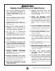
Safety labels warn about machine hazards and ways to prevent injury. The owner of this machine MUST maintain the original location and readability of the labels on the machine. If any label is removed or becomes unreadable, REPLACE that label before using the machine again. Contact Grizzly at (800) 523-4777 or www.grizzly.com to order new labels.
Table of Contents INTRODUCTION ............................................................................................................................... 2 Foreword .................................................................................................................................... 2 Contact Info ................................................................................................................................ 2 Machine Data Sheet.............................................
INTRODUCTION Foreword Contact Info We are proud to offer the Model G0458. This machine is part of a growing Grizzly family of fine woodworking machinery. When used according to the guidelines set forth in this manual, you can expect years of trouble-free, enjoyable operation and proof of Grizzly’s commitment to customer satisfaction. If you have any comments regarding this manual, please write to us at the address below: We are pleased to provide this manual with the Model G0458.
Machine Data Sheet MACHINE DATA SHEET Customer Service #: (570) 546-9663 • To Order Call: (800) 523-4777 • Fax #: (800) 438-5901 MODEL G0458 OPEN-END DRUM SANDER Design Type ...................................................................................................... Floor Model Overall Dimensions: Height ......................................................................................................................50" Width ..................................................................
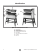
Identification E A G B F C H D Figure . Main controls/components of the sander. A. B. C. D. E. F. G. H.
SECTION 1: SAFETY For Your Own Safety, Read Instruction Manual Before Operating this Machine The purpose of safety symbols is to attract your attention to possible hazardous conditions. This manual uses a series of symbols and signal words which are intended to convey the level of importance of the safety messages. The progression of symbols is described below. Remember that safety messages by themselves do not eliminate danger and are not a substitute for proper accident prevention measures.
Safety Instructions for Machinery 7. ONLY ALLOW TRAINED AND PROPERLY SUPERVISED PERSONNEL TO OPERATE MACHINERY. Make sure operation instructions are safe and clearly understood. 8. KEEP CHILDREN AND VISITORS AWAY. Keep all children and visitors a safe distance from the work area. 9. MAKE WORKSHOP CHILD PROOF. Use padlocks, master switches, and remove start switch keys. 10. NEVER LEAVE WHEN MACHINE IS RUNNING.
Additional Safety for Drum Sanders 1. FEEDING STOCK. DO NOT allow anyone to stand at the outfeed end when feeding your stock. Never sand more than one piece of stock at a time. 6. DUST COLLECTION SYSTEM. Never operate the sander without an adequate dust collection system in place and running. DO NOT jam the workpiece into the machine during operation. Firmly grasp the workpiece in both hands and ease it into the machine using light pressure. 7. UNATTENDED OPERATION.
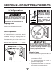
SECTION 2: CIRCUIT REQUIREMENTS 110V Operation Electrocution or fire could result if this machine is not grounded correctly or if your electrical configuration does not comply with local and state codes. Ensure compliance by checking with a qualified electrician! Serious personal injury could occur if you connect the machine to the power source before you have completed the set up process. DO NOT connect the machine to the power source until instructed to do so.
SECTION 3: SET UP Set Up Safety This machine presents serious injury hazards to untrained users. Read through this entire manual to become familiar with the controls and operations before starting the machine! Wear safety glasses during the entire set up process! The Model G0458 is a heavy machine. DO NOT over-exert yourself while unpacking or moving your machine—get assistance.
Inventory After all the parts have been removed from the box, you should have the following items: Box 1: (Figures 1 & 2) Qty A. Drum Sander .............................................. 1 J. Hardware and Tools (Not Shown) — Handwheel ............................................ 1 — Handwheel Handle M10-1.5................... 1 — Phillips Head Screw M6-1 x 25 .............. 1 — Flat Washer 5mm .................................. 1 — Hex Bolt M8-1.25 x 20 ........................... 4 — Hex Nut M8-1.25 ...
Hardware Recognition Chart G0458 18" Open End Belt/Drum Sander -11-
Site Considerations Floor Load The weight and footprint size for your machine is located in the machine data sheet. Some residential floors may require additional reinforcement to support the machine, workpieces, and operator. Working Clearances Consider existing and anticipated needs, size of material to be processed through each machine, and space for auxiliary stands, work tables or other machinery when establishing a location for your new machine. See Figure 3 for the minimum working clearances.
2. Secure a second leg to the top and bottom long brackets with two M8-1.25 x 15 carriage bolts and serrated flange nuts as shown in Figure 5. 4. Build the rest of the stand assembly, as shown in Figure 7, with the remaining hardware. Leg Figure 7. Completed stand assembly. Figure 5. A completed stand leg assembly. 5. 3. Mount a top and bottom short bracket to the left and right sides of the stand leg assembly completed in Step 2 as shown in Figure 6. Secure with two M8-1.
Installing Sander on Stand The sander is very heavy. DO NOT over-exert yourself while unpacking or moving your machine— get assistance. Components and Hardware Needed: Qty Sander ............................................................... 1 Stand Assembly ................................................ 1 Hex Bolts M8-1.25 x 20 ..................................... 4 Flat Washers 8mm ............................................ 8 Figure 8. Sander tipped back on pallet against pulley cover. 4.
5. Lay the stand on the blocks as shown in Figure 10. 9. Tilt the sander upright, as shown in Figure 12, so the rear legs touch the floor. If the legs start to slide when tilting, you MUST have a third person hold the stand from sliding to avoid personal injury or machine damage! Figure 10. Stand resting on blocks. 6. Align the holes, and secure the stand to the sander with the remaining hex bolts, washers, and hex nuts (Figure 11).
Handwheel Dust Port and Bag Components and Hardware Needed: Qty Handwheel Handle ............................................ 1 Handwheel ........................................................ 1 Cap Screw M5-.8 x 10 ....................................... 1 Flat Washer 5mm .............................................. 1 Components and Hardware Needed: Qty Dust Port ........................................................... 1 Dust Bag ............................................................
Dust Collection DO NOT operate the Model G0458 without adequate dust collection. This sander creates substantial amounts of wood dust while operating. Failure to use dust collection can result in short and long-term respiratory illness. You may attach the Model G0458 drum sander to a dust collection system if you do not use the included dust bag. If you are using your own dust collection system, we recommend using a system that can collect a minimum of 400 CFM AT THE DUST PORT.
Recommended Adjustments For your convenience, the adjustments listed below have been performed at the factory and no further setup is required to operate your machine. However, because of the many variables involved with shipping, some of these adjustments may need to be repeated to ensure optimum results. Keep this in mind as you start to use your new drum sander. Step-by-step instructions for these adjustments can be found in SECTION 7: SERVICE ADJUSTMENTS. 1. V-Belt Tensioning (Page 27).
SECTION 4: OPERATIONS Operation Safety Damage to your eyes, lungs, and ears could result from using this machine without proper protective gear. Always wear safety glasses, a respirator, and hearing protection when operating this machine. Depth of Cut The optimum depth of cut will vary based on the type of wood, feed rate, and sandpaper grit. Attempts to remove too much material can cause jamming, wood burning, rapid paper wear or tearing, poor finish, and belt slippage. To set the depth of cut: 1.
Variable Speed The variable speed knob allows you to increase the feed rate from 2–12 FPM. The correct speed to use depends on the type of stock you are using (hardwood vs. softwood) and the stage of finish with that workpiece. As a general rule, a slower feed rate will sand the surface smoother, but runs the risk of burning the wood; a faster feed rate will remove material faster, but runs the risk of overloading the motor or damaging the sandpaper.
Sanding Tips • Replace the sandpaper with a higher grit to achieve a finer finish. • Raise the table a maximum of 1⁄4 turn of the handwheel until the workpiece is the desired thickness. • Reduce snipe when sanding more than one board of the same thickness by feeding them into the sander with the front end of the second board touching the back end of the first board. Choosing Sandpaper There are many types of sanding belts to choose from. We recommend Aluminum Oxide for general workshop environments.
Paper Replacement Tools Needed: Qty Flat Head Screwdriver ...................................... 1 Hex Wrench 4mm .............................................. 1 Hex Wrench 5mm .............................................. 1 Carton Cutter or Utility Knife ............................. 1 6. Loosen the cap screw on the left clamp and remove the sandpaper. 7. Use the old sandpaper as a pattern, or use the pattern in Figure 19, to cut a new piece of sandpaper to the necessary shape.
9. Wrap the sandpaper around the drum (Figure 21), ensuring there are no bubbles or overlapping edges. Figure 21. Wrapping sandpaper around drum. 10. When the sandpaper reaches the right side of the drum, move the sandpaper out of the way with a 4mm wrench and place it into the access hole. 11. Rotate the drum toward you so the wrench rests against the frame as shown in Figure 22. 12.
SECTION 5: ACCESSORIES Aluminum Oxide Sanding Rolls 3" x 10' G3071—60 Grit: Use for thickness sanding and glue removal. G3072—80 Grit: Use for removing planer marks and initial finish sanding. G3073—100 Grit: Use for removing planer marks and initial finish sanding. G3074—120 Grit: Use for finish sanding. G4400—150 Grit: Use for finish sanding. G4401—180 Grit: Use for finish sanding. G4402—220 Grit: Use for finish sanding.
SECTION 6: MAINTENANCE Cleaning Always disconnect power to the machine before performing maintenance. Failure to do this may result in serious personal injury. Schedule For safe and optimum performance from a machine that is used on a daily basis, follow this maintenance schedule and refer to any specific instructions given in this section. Daily Checks and Maintenance: • Loose mounting bolts. • Damaged sanding belt. • Worn switch. • Worn or damaged cords or plugs. • Damaged V-belts.
Feed Belt Drive: Lubricate with lithium grease monthly. Wipe sawdust and dirt impregnated grease off of the chain and gears shown in Figures 28 & 29. Apply fresh lithium grease to the gears and chain. Table Lift Mechanism: Lubricate the table lift screws, chain, and helical gear with lithium grease every six months. Clean the chain and table lift screws (Figure 30), then rub lithium grease onto the chain links and screw threads. Clean the helical gear (Figure 31) and place a dab of grease on the teeth.
V-Belt Tensioning 3. Tools Needed: Qty Hex Wrenches 4 & 8mm ..............................1 Ea Phillips Head Screwdriver ................................. 1 Pry Bar .............................................................. 1 Check the tension of the feed belt V-belt, then adjust the tension by loosening the motor mount cap screws shown in Figure 33 and pushing down on the motor mount to tighten the V-belts. Feed Belt V-Belt Proper tension is important for optimum power transmission.
SECTION 7: SERVICE This section is provided for your convenience—it is not a substitute for the Grizzly Service Department. If you need help troubleshooting, you need replacement parts, or you are unsure of how to perform the procedures in this section, then feel free to call our Technical Support at (570) 546-9663. Troubleshooting Motor & Electrical Symptom Possible Cause Machine does not start or 1. a breaker trips. 2. 3. 4. 5. 6. 7. 8. 9. 1.
Symptom Possible Cause Machine has vibration or 1. Motor or component is loose. noisy operation. 2. V-belts are worn or loose. 3. Motor fan is rubbing on fan cover. 4. Pulley is loose. 5. Machine is incorrectly mounted to the floor. 6. Cast iron motor mount is at fault. 7. Motor bearings are at fault. Possible Solution 1. Inspect for stripped/damaged bolts/nuts, replace/re-tighten with thread locking fluid. 2. Inspect belts, replace and re-tension (see Pages 27 & 30). 3.
Replacing V-Belts Tools Needed: Qty Hex Wrenches 4, 6 & 8mm ..........................1 Ea Phillips Head Screwdriver ................................. 1 Pry Bar .............................................................. 1 Inspect the V-belts closely; if you notice fraying, cracking, glazing, or any other damage, replace the belts. A worn/damaged V-belt will not provide optimum power transmission from the motor to the drum and feed belt. 4.
Pulley Alignment Tools Needed: Qty Hex Wrenches 4 & 8mm ..............................1 Ea Phillips Head Screwdriver ................................. 1 Pry Bar .............................................................. 1 Pulley alignment is another important factor in power transmission and belt life. The pulleys should be parallel to each other and in the same plane (coplaner) for optimum performance.
2. Loosen the lock nut (Figure 38) on the side that the feed belt tracks towards and tension the tracking adjustment screw until the feed belt tracks in the opposite direction. To tension the feed belt: 1. Note: Small tracking changes may take up to three minutes before they are noticeable. Lock Nut Tracking Adjustment Screw Figure 38. Feed belt tracking adjustment bolt. 3.
Feed Belt Replacement Tools Needed: Qty Wrench 12mm ................................................... 2 Hex Wrench 6mm.............................................. 1 An Assistant ...................................................... 1 Replacing the feed belt is a simple process, but will require tensioning and tracking when completed. 5. Have an assistant lift the outside edge of the table, then slide the feed belt off. 6.
Gauge Blocks Table Adjustments Tools Needed: Qty 6' Long 2x4 ........................................................ 1 Miter Saw (or Circular Saw) .............................. 1 Jointer ................................................................ 1 Table Saw ......................................................... 1 Aligning the drums parallel to the conveyor belt (Figure 43) is critical for sanding accuracy. Care should be taken to make the tolerances as close as possible (within 0.
3. Note: A good way to know when they are touching is to rock the drum back and forth while raising the table until you hear or feel contact with the gauge blocks. 4. 5. 6. Lower the table one full crank of the handwheel (taking handwheel free-play into consideration; or in other words, wait until the chain starts moving before starting to count the handwheel rotation). Starting at one end, find the largest size feeler gauge that can pass between the drum and your gauge block.
5. Raise the table until the gauge blocks just touch the drum. 6. Find the largest size feeler gauge that can pass between the front pressure plate and your gauge block. (The feeler gauge should slide with moderate resistance, without forcing the drum to roll.) —If the gap is 0.004" (0.1mm) or less, then no adjustment of the front pressure plate is necessary. —If the gap is more than 0.004" (0.1mm), then the front pressure plate must be adjusted. To adjust the rear pressure plate: 1.
wiring diagram Wiring Diagram ����� ��� � ����� �������������� ����� �������������� ������������������� ������� ����� ��������� ����� ������ ������������� ������������ � � � � � � ���� ��������������������������������� ���������������������������������� �������������������������������� ����������������������������������� ������������������������������������ ���������������������������������� ������������������������������������ �������������������������� G0458 18" Open End Belt/Drum Sander
-38- �� �� �� � � ��� �� �� �� �� �� �� �� �� �� �� �� ��� � �� � �� ��� ��� ��� ����� ����� ��� � ����� ����� �� ����� � �� � � � � �� ��� ��� ��� ��� ��� ��� �� �� �� ��� ��� ��� ��� ��� ��� ��� ��� ��� ��� ��� ��� �� ��� ��� �� �� �� �� ��� ���� ��� ��� �� �� ��� ��� �� �� ��� �� � �� ��� �� �� �� �� ��� � ��� �� �� �� � ��� ��� ��� �� � ��� � �� �� �� ��� �� �� �� �� � ��� ��� �� � �� � �� �� � ��� �� �� ��� � �� �� � ��� �� ��� ��� � �� �� ���� � � ��� � ��� � � �� ��� ��� ��
G0458 Parts List REF PART # DESCRIPTION REF PART # DESCRIPTION 1 2 3 4 5 6 7 8 9 10 11 12 13 14 15 16 17 18 19 20 21 22 23 24 25 26 27 28 29 30 31 32 33 34 35 36 37 38 39 40 41 42 43 44 45 46 47 48 49 50 P0458001 PS05M PW02M PSB03M P0458005 P0458006 PSB33M PS47M PEC06M PLW04M P0458011 P0458012 PAW06M PAW05M PAW04M PSB100M PW01M P0458018 P0458019 P0458020 P0458021 P6003 P0458023 P6003 P0458025 P0458026 P0458027 P0458028 P0458029 P0458030 PK02M P0458032 PSB95M P0458034 PSB38M P0458036 P0458037 PW02M P0
G0458 Parts List REF PART # DESCRIPTION REF PART # DESCRIPTION 100-1 100-2 100-3 100-4 100-5 100-6 101 102 103 104 105 106 107 108 109 110 111 112 113 114 115 116 117 118 119 120 121 122 123 124 125 126 127 128 129 130 131 132 133 134 135 136 137 138 139 140 141 142 143 144 146 147 P0458100-1 P0458100-2 PC300S P0458100-4 P0458100-5 P0458100-6 P0458101 P0458102 P0458103 P0458104 P0458105 P0458106 P0458107 PB95M P6103043 PR03M P0458111 PS68M P0458113 PSS07M P0458115 P0458116 PSB130M P0458118 PHTEK26M P
G0458 Parts List REF PART # DESCRIPTION REF PART # DESCRIPTION 200 201 202 203 204 205 206 207 208 209 210 211 212 213 214 215 216 217 218 219 220 221 222 223 224 225 226 227 228 229 230 231 232 233 234 235 236 237 238 239 241 242 243 244 PSB33M P0458201 PFH43M PFH07M PSS24M PN06M P0458206 PSB142M PSB64M PSB33M P0458210 P0458211 PSB04M P0458213 P0458214 P0502058 P0458216 PSB26M P0458218 PN06M PSS34M PW02M P0458222 P0458223 PLW04M P0458225 PS19M PTLW02M P0458228 PSB33M PW02M PS05M P0458232 P0458233 P0
WARRANTY AND RETURNS Grizzly Industrial, Inc. warrants every product it sells for a period of 1 year to the original purchaser from the date of purchase. This warranty does not apply to defects due directly or indirectly to misuse, abuse, negligence, accidents, repairs or alterations or lack of maintenance.
WARRANTY CARD Name _____________________________________________________________________________ Street _____________________________________________________________________________ City _______________________ State _________________________ Zip _____________________ Phone # ____________________ Email ________________________ Invoice # _________________ Model # ____________________ Order # _______________________ Serial # __________________ The following information is given on a voluntary basis.
FOLD ALONG DOTTED LINE Place Stamp Here GRIZZLY INDUSTRIAL, INC. P.O.
Buy Direct and Save with Grizzly® – Trusted, Proven and a Great Value! Visit Our Website Today And Discover Why Grizzly® Is The Industry Leader! • SECURE ORDERING • ORDERS SHIPPED WITHIN 24 HOURS • E-MAIL RESPONSE WITHIN ONE HOUR -OR- Call Today For A FREE Full Color Catalog