MODEL G0460/G0461 12" SLIDING TABLE SAW OWNER'S MANUAL COPYRIGHT © JANUARY, 2007 BY GRIZZLY INDUSTRIAL, INC. WARNING: NO PORTION OF THIS MANUAL MAY BE REPRODUCED IN ANY SHAPE OR FORM WITHOUT THE WRITTEN APPROVAL OF GRIZZLY INDUSTRIAL, INC.
����������������������������������������������������������������������� �������������������������������������������������������������� ���������������������������������������������������������������������� �������������������������������������������������������������������� ������������������������ ������������������������������������������������������������������ �������������������������������������������������������������������� ����������������������������������������������������������������� ����������
Table of Contents INTRODUCTION ............................................... 2 Foreword ........................................................ 2 Contact Info ................................................... 2 Machine Data Sheet ...................................... 3 Machine Data Sheet ...................................... 3 Identification ................................................... 5 SECTION 1: SAFETY ....................................... 7 Safety Instructions for Machinery .............
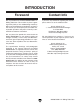
INTRODUCTION Foreword Contact Info We are proud to offer the Model G0460/G0461 12" Sliding Table Saw. This machine is part of a growing Grizzly family of fine woodworking machinery. When used according to the guidelines set forth in this manual, you can expect years of trouble-free, enjoyable operation and proof of Grizzly’s commitment to customer satisfaction.
Machine Data Sheet MACHINE DATA SHEET Customer Service #: (570) 546-9663 • To Order Call: (800) 523-4777 • Fax #: (800) 438-5901 MODEL G0460/G0461 12" SLIDING TABLE SAW Overall Dimensions: Overall Size (with Cross Slide Fence and Sliding Table Extended) .....................................................132" W x 136" D x 48" H Table Height ......................................................................................................................................................................
�������������� �������������� ������������������������������������������������������������������������������������������ ������������������������������������������� ��� ��� ��� ��������� ������������� ��� ��� ��� ������������� ���������� ������������� ���������� ��� ��� ��� ��� ������������� ��������� �������������������� ��� ��� ��� ������������� ������������������������������ -4- ��� ������������� �������������������� G0460/G0461 12" Sliding Table Saw
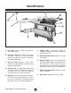
Identification A D B E G C F H J I Figure 1. Main view of machine features and controls. A. Flip Stops: Used for quick measurements when crosscutting. B. Crosscut Fence: Used during crosscutting operations. Features a scale and multiple flip-style stop blocks for precise, repeatable crosscutting operations. C. Crosscut Table: Provides a wide, stable platform for supporting full-size panels during crosscutting operations. D.
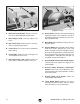
K Q L R T U V M S N O W P Figure 2. Fence controls. Figure 3. Blades. K. Rip Fence Lock Handle: Secures the fence face on its forward/backward slide track. Q. Riving Knife: Maintains kerf opening during cutting operations. This function is crucial to preventing kickback caused by the kerf closing behind the blade. L. Micro-Adjust Knob: Precisely adjusts the fence. M. Rip Fence Scale: Allows precise measurement of rip cutting operations. N.
SECTION 1: SAFETY For Your Own Safety, Read Instruction Manual Before Operating this Machine The purpose of safety symbols is to attract your attention to possible hazardous conditions. This manual uses a series of symbols and signal words which are intended to convey the level of importance of the safety messages. The progression of symbols is described below. Remember that safety messages by themselves do not eliminate danger and are not a substitute for proper accident prevention measures.
Safety Instructions for Machinery 7. ONLY ALLOW TRAINED AND PROPERLY SUPERVISED PERSONNEL TO OPERATE MACHINERY. Make sure operation instructions are safe and clearly understood. 8. KEEP CHILDREN AND VISITORS AWAY. Keep all children and visitors a safe distance from the work area. 9. MAKE WORKSHOP CHILD PROOF. Use padlocks, master switches, and remove start switch keys. 10. NEVER LEAVE WHEN MACHINE IS RUNNING.
Safety Instructions for Sliding Table Saws 1. SAFETY ACCESSORIES. Always use the blade guard and riving knife on all ''throughsawing'' operations. Through-sawing operations are those when the blade cuts completely through the workpiece. 2. KICKBACK. Kickback is defined as high speed expulsion of stock from the table saw toward the operator. Until you have a clear understanding of kickback and how it occurs, DO NOT operate this table saw! 3. WORKPIECE CONTROL.
Statistics prove that most common accidents among table saw users can be linked to kickback. Kickback is typically defined as the high-speed expulsion of stock from the table saw toward its operator. In addition to the danger of the operator or others in the area being struck by the flying stock, the operator’s hands can be pulled into the blade during the kickback. • Make multiple, shallow passes when performing a non-through cut. Making a deep non-through cut greatly increases the chance of kickback.
Glossary of Terms The following is a list of common definitions, terms and phrases used throughout this manual. Become familiar with these terms for assembling, adjusting or operating this machine. Your safety is VERY important to us at Grizzly! Arbor: A metal shaft extending from the drive mechanism on which the saw blade is mounted. Bevel Edge Cut: Tilting the arbor and saw blade to an angle between 0° and 45° to cut a beveled edge onto a workpiece.
SECTION 2: CIRCUIT REQUIREMENTS 220V Plug/Connection Type Serious personal injury could occur if you connect the machine to the power source before you have completed the setup process. DO NOT connect the machine to the power source until instructed to do so. G0460 220V 1-Phase .................................L6-30 G0461 220V 3-Phase ............................... L15-30 Full Load Amperage Draw G0460 5 HP 220V 1-Phase ...................22 Amps G0461 7.5 HP 220V 3-Phase ................ 20 Amps G0461 7.
Rewiring to 440V Grounding In the event of an electrical short, grounding reduces the risk of electric shock. Improper connections of the electrical-grounding conductor increase the risk of electric shock. Ensure that this machine is properly grounded before operating it. Electrocution or fire could result if this machine is not grounded correctly or if your electrical configuration does not comply with local and state codes.
3. Remove the motor junction box cover (see Figure 8). 5. Remove the magnetic switch cover. 6. Replace the original magnetic switch assembly with the assembly included in the 440V conversion kit. Set the dial on the new overload relay to 11A (Figure 9). Motor Junction Box Magnetic Contactor Figure 8. Motor location. 4. Overload Relay Dial Rewire the motor per the diagram on the inside of the motor junction box, using the additional wiring nuts included with the 440V conversion kit.
SECTION 3: SETUP Setup Safety This machine presents serious injury hazards to untrained users. Read through this entire manual to become familiar with the controls and operations before starting the machine! Wear safety glasses during the entire setup process! The Model G0460/G0461 is a very heavy machine. Serious personal injury may occur if safe moving methods are not followed. To be safe, get assistance and use power equipment when moving the crate and removing the machine from the crate.
Clean Up Inventory The unpainted surfaces are coated with a waxy oil to prevent corrosion during shipment. Remove this protective coating with a solvent cleaner or citrus-based degreaser such as Grizzly’s G7895 Citrus Degreaser. To clean thoroughly, some parts must be removed. For optimum performance from your machine, clean all moving parts or sliding contact surfaces. Avoid chlorine-based solvents, such as acetone or brake parts cleaner that may damage painted surfaces.
H. I. J. K. L. Lock Plate................................................... 1 Crosscut Aluminium Fence ........................ 1 Crosscut Table ........................................... 1 Flip Stops w/Knobs, T-Nuts & Washers ..... 2 Adjustable Handles .................................... 2 P. Hold-down .................................................. 1 Q. Edge Shoe.................................................. 1 P H I J Q K L Figure 15. Included accessories. Figure 13.
Hardware Recognition Chart -18- G0460/G0461 12" Sliding Table Saw
Site Considerations Moving & Placing Base Unit Floor Load Most commercial floors are suitable for this machine. Residential floors may require additional reinforcement to support the machine and operator. Refer to the Machine Data Sheet on Page 3 for details about the weight and foot print size. Placement Consider existing and anticipated needs, size of material to be processed through your machine, and space for auxiliary stands, work tables or other machinery when establishing a location for your saw.
Mounting to Shop Floor Although not required, we recommend that you mount your new machine to the floor. Because this is an optional step and floor materials may vary, floor mounting hardware is not included. However you decide to mount your machine, we strongly suggest leveling the machine with a precision level before bolting it down. Bolting to Concrete Floors Figure 18. Typical lag shield anchor and lag bolt.
Extension Tables 4. Components and Hardware Needed: Qty Large Extension Wing ....................................... 1 Small Extension Wing w/Set Screws ................ 1 Support Leg w/Hex Bolt & Nut .......................... 1 Cap Screws M8-1.25 x 25 (Small Wing/Table) ............................................ 2 Lock Washers 8mm (Small Wing/Table) ........... 2 Flat Washers 8mm (Small Wing/Table) ............ 2 Cap Screws M8-1.25 x 25 (Large Wing/Table) ............................................
Main Blade Scoring Blade Arbor Components and Hardware Needed: Qty Blade 12" (Not Included) ....................................1 Riving Knife ........................................................1 To install the blade: 1. DISCONNECT SAW FROM POWER! 2. Open the cabinet and remove the red motor support bolt, shown in Figure 23, by removing the nut and tilting the blade assembly to clear the bolt. Main Blade Arbor Figure 24. Main blade arbor components. 5.
Rip Fence and Scale 4. Components and Hardware Needed: Qty Rip Fence ...........................................................1 Round Rail ..........................................................1 Rip Fence Body ..................................................1 Square Tube w/Scale .........................................1 Flat Washers 6mm (Scale/Table) .......................5 Hex Nuts M6-1 (Scale/Table) .............................5 Cap Screws M6-1 x 20 (Scale/Table) ................
7. Slide the rip fence all the way onto the clamping plate (Figure 29) and secure it by rotating the locking handle on top of the rip fence body. Locking Handle 11. Tighten the hex nuts on that stud to secure the rail to the table on that end (one of the nuts acts as a jam nut and tightens against the other one to keep the setting). Note: Leave the center studs loose until the adjustments are complete. 12. Slide the fence to the middle of the round rail, and replace the stop screw. 13.
Riving Knife 15. Check if the bottom of the rip fence rests on the surface of the table. Note: The rip fence will scratch the table if the ride height is not adjusted correctly. —If the rip fence DOES NOT rest on the table, then the fence is correctly adjusted. To install the riving knife: 1. DISCONNECT SAW FROM POWER! 2. Loosen the riving knife center bolt, slide the riving knife between the plates as shown in Figure 33, and slightly tighten.
5. Check the blade alignment on both sides of the riving knife with a straightedge, as shown in Figure 35. 7. Slide the table all the way forward to access the blade arbor. 8. Loosen the flange bolt securing the lower blade guard, slide the flange bolt up, and pull open the lower blade guard. 9. Loosen the riving knife center bolt and remove the riving knife. —If the straightedge touches the riving knife evenly on both sides, go to Step 5.
Scoring Blade 5. Install the blade set with the teeth facing the opposite direction as the main blade, then reinstall the arbor flange and the arbor nut. Most scoring blade sets consist of an inner and outer blade and internal shims. The shims are provided so the scoring blade thickness can be adjusted to match the kerf thickness of the main blade. The requirements for the G0460/G0461 scoring blade are an 80mm outside diameter with a 20mm arbor hole. 6.
Aligning Blades The scoring blade must be aligned with the main blade to ensure satisfactory cutting results. 5. Use the adjustment controls to move the scoring blade so that the rip fence can touch both the scoring blade and the main blade. 6. Install the riving knife, making sure it is aligned with the blades. Crosscut Table To align the blades and riving knife: 1. DISCONNECT SAW FROM POWER! 2. Move the blade tilt to 0° (blade 90° to table), and raise the main blade all the way up. 3.
2. Slide the lock plate into the T-slot in the side of the sliding table. 3. With the help of an assistant, place the crosscut table on the pivot pin of the swing arm and over the studs of the lock plate (see Figure 43). Forward Mounting Points Crosscut Table Leg Rear Mounting Points Pivot Pin Crosscut Fence Knobs T-Slot Figure 44. Crosscut fence mounting. Figure 43. Installing the crosscut table. 4. Lock the crosscut table in place with the adjustable handles. Crosscut Fence 2.
3. Thread the knobs onto the T-bolts to secure the crosscut fence. 4. Unlock the fence extension and slide the flip stops into the fence as shown in Figure 46. Dust Collection Components and Hardware Needed: Qty Blade Guard Dust Hood .....................................1 Flat Washer 8mm ...............................................1 Adjustable Handle M8-1.25 x 28 ........................1 5" Dust Hose (not included) ...............................1 5" Hose Clamp (not included) .......................
Test Run 5. —When operating correctly, the machine runs smoothly with little or no vibration or rubbing noises. Once the assembly is complete, test run your machine to make sure it runs properly and is ready for regular operation. —Investigate and correct strange or unusual noises or vibrations before operating the machine further. Always disconnect the machine from power when investigating or correcting potential problems.
SECTION 4: OPERATIONS Operation Safety Operation Tips Damage to your eyes, lungs, and ears could result from using this machine without proper protective gear. Always wear safety glasses, a respirator, and hearing protection when operating this machine. Your safety is important. The tips below are intended to supplement SECTION 1: SAFETY. But remember, no safety list can be comprehensive of every situation. The operator is ultimately responsible for their own safety, as well as the safety of bystanders.
Changing Blades The Model G0460/G0461 performs best when high quality, sharp blades are used. Therefore, whenever the blades start to get dull, we recommend that you have them resharpened or replaced with a new blade. To change the blades: 1. DISCONNECT SAW FROM POWER! 2. Move the blade tilt to 0° (blade 90° to table) and raise the main blade as high as it will go. 3.
Rip Cutting The Model G0460/G0461 easily rips 4' x 8' panels (Figure 50). The sliding table removes the burden of sliding a large and heavy panel over a stationary table surface. This saw also can rip smaller boards using the rip fence in the same manner as a traditional table saw (Figure 51). Smaller, lighter boards are easier to slide across the stationary cast iron table surface to the right of the saw blade. 2.
Rip cutting with the rip fence: 1. Remove the crosscut fence. 2. Use the table lock (Figure 53) to lock the sliding table into a stationary position. (To lock the sliding table, you have to engage the lock and center the table in front of the machine. The table will automatically lock when it is in the correct position.) 4. Lift the lock lever and position the rip fence to approximately the desired width-of-cut. 5.
Crosscutting This machine can also crosscut workpieces while using the rip fence as a cut-off gauge (Figure 59). The Model G0460/G0461 can crosscut 4' x 8' panels with the fence in the forward or rear position, although it is easier to load full size panels with the crosscut fence mounted in the forward position (see Figure 57). Forward Mounted Crosscut Fence Figure 59. Crosscutting workpieces using the rip fence as a cut-off gauge.
Crosscutting full size panels: 1. Install the crosscut fence in the forward mounting points shown in Figure 60 and lock it in place. Forward Mounting Points 2. 4. Load the workpiece onto the table saw. The setup should look similar to Figure 58. 5. Once all the necessary safety precautions have been taken, perform the cutting operation. Crosscutting using the rip fence as a cut-off gauge: 1. Install the crosscut fence in the rear mounting points shown in Figure 60 and lock it in place. 2.
Miter Cutting 3. The miter fence allows miter cuts from 0° to 90°. The table mounted miter scale has a resolution of 1°. Angle Gauge To perform a miter cut: 1. Slide the crosscut table to the front edge of the sliding table and lock it in place. 2. Install the fence as shown in Figures 62 & 63 for angled cuts. Set the fence to the desired angle using the crosscut table angle gauge and lock the angle with the crosscutting fence knob (see Figure 64). Figure 64. Crosscut table angle gauge. 4.
SECTION 5: ACCESSORIES H3308—SHOP FOX® Push Stick Measuring 131⁄2" overall, this push stick allows the operator to keep their hands at a safe distance away from the blade or cutter. H3771—Blade Loc® This simple tool secures the blade during blade changes, keeping your hands safe and your expensive blade from being damaged. Figure 66. H3308 SHOP FOX® Push Stick. Figure 68. H3771 Blade Loc®.
G7984—Face Shield H1298—Dust Sealed Safety Glasses H1300—UV Blocking, Clear Safety Glasses H2347—Uvex® Spitfire Safety Glasses H0736—Shop Fox® Safety Glasses Safety Glasses are essential to every shop. If you already have a pair, buy extras for visitors or employees.
SECTION 6: MAINTENANCE Cleaning Always disconnect power to the machine before performing maintenance. Failure to do this may result in serious personal injury. Schedule For optimum performance from your machine, follow this maintenance schedule and refer to any specific instructions given in this section. Daily Check • • • • Loose mounting bolts. Worn or damaged saw blade. Worn or damaged switches or wires. Any other unsafe condition.
Lubrication • Blade height and tilt worm gears. Lubricate with an automotive wheel bearing grease (see Figure 75). The bearings are sealed and pre-lubricated and require no lubrication during their usable life. However, your saw components will operate at their best if the bearing surfaces are kept clean—this is especially important for the trunnion bearings. Blade Height Worm Gear Lubricate the areas indicated below every 6-12 months, depending on frequency of use. • Sliding table ways.
SECTION 7: SERVICE Review the troubleshooting and procedures in this section to fix or adjust your machine if a problem develops. If you need replacement parts or you are unsure of your repair skills, then feel free to call our Technical Support at (570) 546-9663. Troubleshooting Motor & Electrical Symptom Machine does not start or a breaker trips. Possible Cause Possible Solution 1. Start capacitor is at fault (G0460). 2. Emergency stop push-button is engaged/faulty. 3.
Symptom Possible Cause Machine has vibration or noisy 1. Motor or component is loose. operation. 2. Motor fan is rubbing on fan cover. 3. Blade is at fault. 4. V-belt(s) worn or loose. 5. Pulley is loose. 6. Motor mount loose/broken. 7. Arbor pulley is loose. 8. Arbor bearings are at fault. 9. Motor bearings are at fault. 10. Blade is at fault. Possible Solution 1. Inspect/replace stripped or damaged bolts/ nuts, and re-tighten with thread locking fluid. 2.
Replacing Belts To ensure optimal power transmission from the motor to the blades, the belts must be in good condition (free from cracks, fraying and wear) and operate under proper tension. 5. Remove the old V-belt set and replace them with a new V-belt set. Note: The motor V-belts should always be replaced as a matched set to ensure maximum belt longevity and power transmission. 6.
Blade Tilt The blade tilt is calibrated at the factory, but can be adjusted if it changes during the life of the machine. 5. Turn the handwheel until the blade and square are flush from top to bottom. 6. Snug the 0° tilt stop nut against the leadscrew nut and tighten the set screw. 7. Recheck the blade with the square to ensure the nut has not been over-tightened. 8. Adjust the blade angle until you hit the 45° positive stop. Check the bevel with an adjustable square set to 45°. 9.
Squaring Crosscut Fence to Blade 3. Use the crosscut fence to cut 1⁄2" off of each side of the test piece, then cut side 1 again (make 5 cuts total). 4. Measure the test piece diagonally from corner-to-corner as shown in Figure 80. Squaring the crosscut fence to the blade ensures that cuts made with the crosscut fence will be square. This procedure consists of cutting a piece of scrap plywood five times, then adjusting the fence as necessary.
Sliding Table Parallelism 4. Note: Use a dial indicator for the most accurate results. To adjust the sliding table parallel with the main blade: 1. Move the blade tilt to 0° (blade 90° to table), and raise the main blade as high as it will go. 2. Loosen the sliding table mounting nuts (refer to Figures 82–84). Using an adjustable square or a dial indicator, measure the distance (A) between the miter slot and the front of the blade as shown in Figure 85. 5.
G0460 Electrical Components Contactor Thermal Overload Relay Junction Box Wiring Motor Wiring G0460/G0461 12" Sliding Table Saw -49-
G0460 Wiring Diagram �������� ����������� �� ��������� ��� ��� ���� ������ �� ��������� �� ��� ��� ���� ��� �� ���������� �� �� �� ���������������������� ��� �� ��� � � � �� � �� �� ��� ����� ������ �� ��� ���������� ���������������� ������ � ��� � � ��� �������� ��� ������� ������� ������ ������ �� �� ����� ���� ������ ������� ������ ����� ��� �������� ��� ���� ����� ��� ���������� ����������������������������������� ���� ������� ��� ��������� ���� ������ ���������������
G0461 Electrical Components Contactor 220V Switch Shown Thermal Overload Relay Motor Wiring at 220V G0460/G0461 12" Sliding Table Saw Junction Box Wiring -51-
G0461 Wiring Diagram at 220V �������� ����������� �� ��������� ��� ��� ���� ������ �� ��������� �� ��� ��� ���� ��� �� ���������� �� �� �� ���������������������� ��� �� �� ��� � � � �� � �� ��� ����� ������ �� ��� ����������� ���������������� ������ ��� ��� ��� �������� ��� � � � � � ������ ������ � � ������� ������� � � �� �� �� ����� ���� ������ ������� ������ ����� ��� �������� ��� ���� ����� ��� ���������� ����������������������������������� ���� ������� ��� ����
G0461 Wiring Diagram at 440V �������� ����������� �� ��� ���� �� ��������� �� ��� ��� ���� ��� �� ���������� �� �� ���������������������� ��� ������ ��������� ��� �� �� ��� � � � �� � �� ��� ����� ������ �� ��� ���������� ������ ���������������� ������ �� �� �� �� �������� ��� � � ������ ������ � � ������� ������� � � � � � �� �� �� ����� ���� ������ ������� ������ ����� ��� �������� ��� ���� ����� ��� ���������� ����������������������������������� ���� ������� ��� �����
SECTION 8: PARTS Main Body � �� ��� �� �� ��� �� �� �� �� �� � �� �� � � ��� ��� ��� ��� �� �� �� ��� �� �� �� �� -54- ��� G0460/G0461 12" Sliding Table Saw
Main Body Parts List REF PART # DESCRIPTION 1 2 3 4 10 12 13 14 15 16 40 41 78 81 154 158 202 278 301 307 329 333 P0460001 P0588002 PW01M PSB13M P0460010 PSB02M P0588013 PSB26M P0588015 PSB49M PN09M PW06M PB137M PN32M P0460154 P0460158 P0588202 P0588278 P0460301 P0588307 P0460329 P0460333 BODY TABLE FLAT WASHER 8MM CAP SCREW M8-1.25 X 30 COVER PLATE CAP SCREW M6-1 X 20 ADJUSTMENT BOLT COVER CAP SCREW M6-1 X 12 MOTOR COVER CAP SCREW M6-1 X 60 HEX NUT M12-1.
Extension Tables �� �� �� �� �� �� �� �� �� �� � �� �� �� � �� �� �� �� �� � �� �� �� �� �� � �� �� �� �� �� ��� REF PART # DESCRIPTION REF PART # DESCRIPTION 2 3 8 17 18 19 20 21 22 23 24 25 26 27 P0588002 PW01M P0588008 P0588017 PFH07M P0588019 PSB13M PSS16M PN03M P0588023 PB34M PN02M P0588026 PB138M TABLE FLAT WASHER 8MM MAG. SWITCH 220V-75HP (G0461) TABLE INSERT FLAT HD SCR M5-.8 X 10 EXTENSION WING (FRONT) CAP SCREW M8-1.25 X 30 SET SCREW M8-1.25 X 10 HEX NUT M8-1.
Sliding Table �� �� �� �� �� �� �� ��� �� �� �� �� �� �� �� ��� ��� �� �� �� �� �� �� �������������� ��� ��� ��� �� �� �� �� �� �� �� �� �� �� �� �� �� �� �� � �� �� �� �� �� �� �� �� �� ���� �� � � ��� ��� ��� ��� � ����� �� ��� �� G0460/G0461 12" Sliding Table Saw ��� ��� ������������� �������������� ��������� -57-
Sliding Table Parts List REF PART # DESCRIPTION REF PART # DESCRIPTION 3 6 8 8-1 8-2 8-3 8-4 9 42 43 44 45 46 47 48 49 50A 51A 52 53 54 55 56 57 58 59 60 61 62 FLAT WASHER 8MM SWITCH BASE MAG. SWITCH 220V-7.5HP 3Ø & 5HP 1Ø MAG. SWITCH REAR COVER CONTACTOR 220V OVERLOAD RELAY 21-25A MAG SWITCH FRONT COVER CAP SCREW M6-1 X 16 SLIDING TABLE SLIDING TABLE END COVER CAP SCREW M6-1 X 16 RUBBER PLATE FLAT HD SCR M8-1.
Crosscut Table �� �� �� �� �� �� �� ��� �� �� �� ��� ��� ��� ��� ��� �� �� ��� ��� �� ��� �� ��� �� �� �� ��� ��� ��� ��� ��� �� �� �� ��� �� ��� ��� � ��� ��� �� �� ��� ��� ��� G0460/G0461 12" Sliding Table Saw -59-
Crosscut Table Parts List -60- REF PART # DESCRIPTION 9 20 22 25 29 37 82 84 85 86 87 89 90 91 92 93 93A 94A 95A 96A 97 98 99 100 101 102 103 104 105 106 107 108 117 118 188 189 262 265 PSB01M PSB13M PN03M PN02M PN01M PSB03M P0460082 P0588084 PSB04M PSS09M P0460087 P0588089 P0588090 PW04M P0588092 P0460093 P0460093A P0588094A P6901 P0588096A P0588097 P0588098 P0588099 PFH30M P0588101 P0588102 P0588103 PSB117M P0588105 P0460106 P0588107 PN28M PW01M PLN04M P0460188 P0588189 P6204 P0588265 CAP SCREW M6-
Crosscut Fence ��� ��� ��� ��� ��� ��� ��� ��� ��� ��� ���� ��� ��� ��� ��� ��� ��� ��� ��� ��� ��� ��� ��� ��� ��� ��� ��� ��� ��� ��� �� ��� REF PART # DESCRIPTION REF PART # DESCRIPTION 29 109 110 111 112 113 114 115 116 117 118 119 120 PN01M P0588109 P0588110 P0588111 PW01M PW03M P0588114 P0588115 P0588116 PW01M PLN04M P0460119 P0460120 HEX NUT M6-1 STOP PLATE NYLON PAD KNOB M6-1 X 35 FLAT WASHER 8MM FLAT WASHER 6MM CLAMPING BASE T-NUT M6-1 CLAMPING ARBOR FLAT WASHER 8MM LOCK NUT M8
Rip Fence �� ��� ��� ��� ��� �� ��� ��� ��� ��� ��� ��� �� ��� ��� ��� ��� ��� ��� ��� ��� ��� ��� ��� ��� ��� ��� ��� REF PART # DESCRIPTION REF PART # DESCRIPTION 41 28 63 104 132 133 134 135 136 137 138 139 140 142 PW06M PN13M P0588063 PSB117M P0588132 PR06M P0588134 P0588135 PR36M P0588137 P0460138 P0588139 P0588140 P0588142 FLAT WASHER 12MM HEX NUT M16-2 BALL KNOB BUTTON HD CAP SCR M5-.
Tilt Assembly ��� �� ��� ��� ��� ��� ��� ��� ��� ��� ��� � ��� ��� ��� ��� � ��� �� �� � ��� ��� ��� �� ��� ��� ��� � ��� ��� �� �� ��� ��� ��� ��� ��� ��� ��� ��� ��� ��� ��� ��� ��� ��� ��� REF PART # DESCRIPTION REF PART # DESCRIPTION 3 13 22 29 40 41 44 118 156 160 161 162 163 164 165 166 169 170 171 173 174 PW01M P0588013 PN03M PN01M PN09M PW06M PSB01M PLN04M PSB40M P0588160 P0588161 P0588162 P0588163 P0588164 P0588165 P0588166 P0588169 P0588170 P0588171 P0588173 P05
Motor Assembly ��� ��� �� ��� ��� ��� ���� ��� ��� ��� �� ��� ��� �� ��� � ��� ��� ��� ��� ��� ��� ��� �� �� ��� ��� ��� ��� ��� ��� ��� ��� ��� ��� ��� ��� ��� ��� ����������� ���������� ����� ����� ����� ��� ��� ��� � ��� ��� ����� ����� ��� ��� ����� ��� REF PART # DESCRIPTION REF PART # DESCRIPTION 24 25 91 101 118 164 193 194 195 196 197 198 200 201 203 204 205 206 207 208 209 210 211 211A 212 213 PB34M PN02M PW04M P0588101 PLN04M P0588164 P0588193 PFH23M PFH11M P0588
Arbor Assembly ��� ��� ��� ��� ��� ��� ��� ��� ��� ��� ��� ��� ��� ��� � ��� ��� ��� ��� ��� ��� ��� ��� �� ��� ��� ��� ��� ��� ��� ��� ��� ��� ��� ��� ��� ��� ��� ��� ��� ��� REF PART # DESCRIPTION REF PART # DESCRIPTION 3 25 118 174 230 232 233 234 235 236 237 238 239 240 241 242 243 PW01M PN02M PLN04M P0588174 P0588230 P0588232 PK47M PR29M P0588235 P0588236 P6002 P0588238 P0588239 PSS02M P0588241 PSB12M P0588243 FLAT WASHER 8MM HEX NUT M10-1.5 LOCK NUT M8-1.
WARRANTY AND RETURNS Grizzly Industrial, Inc. warrants every product it sells for a period of 1 year to the original purchaser from the date of purchase. This warranty does not apply to defects due directly or indirectly to misuse, abuse, negligence, accidents, repairs or alterations or lack of maintenance.
WARRANTY CARD Name _____________________________________________________________________________ Street _____________________________________________________________________________ City _______________________ State _________________________ Zip _____________________ Phone # ____________________ Email ________________________ Invoice # _________________ Model # ____________________ Order # _______________________ Serial # __________________ The following information is given on a voluntary basis.
FOLD ALONG DOTTED LINE Place Stamp Here GRIZZLY INDUSTRIAL, INC. P.O.
����������������������������������������������������������������������� ������������������������������������� ������������������������������������ ����������������� �������������������������������� ��������������������������������� ���� ��������������������� ������������������