MODEL G0462 WOOD LATHE w/DIGITAL READOUT OWNER'S Manual Copyright © APRIL, 2010 By Grizzly Industrial, Inc. Warning: No portion of this manual may be reproduced in any shape Or form without the written approval of Grizzly Industrial, inc.
This manual provides critical safety instructions on the proper setup, operation, maintenance and service of this machine/equipment. Failure to read, understand and follow the instructions given in this manual may result in serious personal injury, including amputation, electrocution or death. The owner of this machine/equipment is solely responsible for its safe use.
Table of Contents INTRODUCTION................................................ 2 Manual Accuracy............................................ 2 Contact Info.................................................... 2 Machine Description....................................... 2 Identification.................................................... 3 Machine Data Sheet....................................... 4 SECTION 1: SAFETY........................................ 6 Safety Instructions for Machinery...................
INTRODUCTION Manual Accuracy Contact Info We are proud to offer this manual with your new machine! We've made every effort to be exact with the instructions, specifications, drawings, and photographs of the machine we used when writing this manual. However, sometimes we still make an occasional mistake. We stand behind our machines. If you have any service questions, parts requests or general questions about the machine, please call or write us at the location listed below.
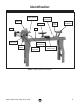
Identification Spindle & Spur Center Tailstock Lock Lever Digital Readout Live Center Tool Rest Motor Tailstock Handwheel Bed Head Lock Lever Variable Speed Lever Power Switch Head Pivot Lock Pin Tool Rest Base w/Pivot Arm Figure 1. Model G0462 identification. G0462 Wood Lathe (Mfg.
Machine Data Sheet MACHINE DATA SHEET Customer Service #: (570) 546-9663 · To Order Call: (800) 523-4777 · Fax #: (800) 438-5901 MODEL G0462 WOOD LATHE WITH DIGITAL READOUT Product Dimensions: Weight.............................................................................................................................................................. 287 lbs. Length/Width/Height.......................................................................................................................
Spindle Information Spindle Type..................................................................................................................................... Right Hand Spindle Taper.............................................................................................................................................MT#2 Spindle Size................................................................................................................................................. 1 in.
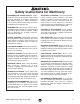
SECTION 1: SAFETY For Your Own Safety, Read Instruction Manual Before Operating this Machine The purpose of safety symbols is to attract your attention to possible hazardous conditions. This manual uses a series of symbols and signal words intended to convey the level of importance of the safety messages. The progression of symbols is described below. Remember that safety messages by themselves do not eliminate danger and are not a substitute for proper accident prevention measures.
Safety Instructions for Machinery DISCONNECTING POWER SUPPLY. Always disconnect machine from power supply before servicing, adjusting, or changing cutting tools (bits, blades, cutters, etc.). Make sure switch is inOFFpositionbeforereconnectingtoavoidan unexpectedorunintentionalstart. INTENDED USE.Onlyusethemachineforits intendedpurposeandonlyuserecommended accessories.
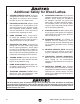
Additional Safety for Wood Lathes 1. KEEPING GUARDS IN PLACE. To prevent entanglement hazards, make sure all doors and guards are secured in place and that the lathe sits on a flat, stable surface. 2. EYE/FACE PROTECTION. Airborne wood dust and debris can be hazardous to the eyes/face and may cause allergies or longterm respiratory health problems. Always wear eye protection or a face shield and a respirator when operating the lathe. 3. 4. USING CENTERS.
SECTION 2: CIRCUIT REQUIREMENTS 110V Operation Power Connection Device The Model G0462 comes prewired with a NEMA 5-15 plug, as shown in Figure 2. GROUNDED 5-15 RECEPTACLE Serious personal injury could occur if you connect the machine to power before completing the setup process. DO NOT connect the machine to the power until instructed later in this manual. Grounding Prong 5-15 PLUG Electrocution or fire could result if machine is not grounded and installed in compliance with electrical codes.
SECTION 3: SETUP Needed for Setup This machine presents serious injury hazards to untrained users. Read through this entire manual to become familiar with the controls and operations before starting the machine! Wear safety glasses during the entire setup process! This machine and its components are very heavy. Get lifting help or use power lifting equipment such as a forklift to move heavy items. The following are needed to complete the setup process, but are not included with your machine.
Inventory A The following is a list of the small components shipped with your machine. Lay the components out to inventory them. B Note: If you can't find an item on this list, check the mounting location on the machine or examine the packaging materials carefully. Occasionally we pre-install certain components for shipping purposes. Box 1 Inventory (Figure 3) Qty A. Lathe Unit.................................................... 1 B. Faceplate 6"................................................ 1 C.
Cleanup Gasoline and petroleum products have low flash points and can explode or cause fire if used to clean machinery. Avo i d u sing t h e s e p r o d u c t s to c l e a n m a c hin e r y. The unpainted surfaces of your machine are coated with a heavy-duty rust preventative that prevents corrosion during shipment and storage. This rust preventative has been your machine's close ally and guardian since it left the factory.
Site Considerations Weight Load Physical Environment Refer to the Machine Data Sheet for the weight of your machine. Make sure that the surface upon which the machine is placed will bear the weight of the machine, additional equipment that may be installed on the machine, and the heaviest workpiece that will be used. Additionally, consider the weight of the operator and any dynamic loading that may occur when operating the machine.
Mounting Although not required, we recommend that you mount your new machine to the floor. Because this is an optional step and floor materials may vary, floor mounting hardware is not included. Generally, you can either bolt your machine to the floor or mount it on machine mounts. Both options are described below. Whichever option you choose, it is necessary to level your machine with a precision level.
Assembly 3. Secure the lathe to the legs with the (8) M8-1.25 x 35 cap screws and 8mm lock washers, as shown in Figure 11. To mount the lathe to the stand: 1. Stand the legs up approximately 41" apart, then get them reasonably aligned, as shown in Figure 10. x8 Figure 11. Securing lathe to the stand leg. 4. Install the tool rest lock lever to secure the tool rest, as shown in Figure 12. Figure 10. Stand legs approximately 41" apart to prepare for mounting the lathe. 2.
5. Align the quill keyway with the entry hole of the quill lock lever (see Figure 13), then install the lever into the tailstock so that the end of it mates with the quill keyway. Note: Make sure the dog-point end of the lock lever fits into the quill keyway so that the quill can move in and out of the tailstock without rotating.
5. Listen to and watch for abnormal noises or actions. The lathe should run smoothly with little or no vibration or rubbing noises. — Strange or unnatural noises should be investigated and corrected before operating the machine further. Always unplug the machine when investigating or correcting any situation with the machine. 6. Turn the lathe OFF, then remove the yellow switch disabling key from the paddle switch, as shown in Figure 15.
SECTION 4: OPERATIONS Adjusting Head Damage to your eyes and lungs could result from using this machine without proper protective gear. Always wear safety glasses and a respirator when operating this machine. The Model G0462 headstock can be positioned anywhere along the bed and pivoted up to 180˚. To position the headstock along the length of the bed: 1. DISCONNECT LATHE FROM POWER! 2. Loose hair and clothing could get caught in machinery and cause serious personal injury.
To pivot the headstock: 1. DISCONNECT LATHE FROM POWER! Adjusting Tailstock Position 2. Make sure the head lock lever is tight. 3. Pull the pivot lock pin out (see Figure 18) and pivot the headstock clockwise 90˚ or 180˚, as shown in Figure 19. Pivot Lock Pin Head Lock Lever The tailstock is equipped with a cam-action clamping system to secure it. When the lock lever is tightened, a locking plate lifts up and secures the tool rest to the bed.
Adjusting Tool Rest The tool rest is equipped with a cam-action clamping system to secure it. When the base lock lever is tightened, a clamping plate lifts up and secures the tool rest to the bed. For safe and good turning results, we recommend positioning the tool rest approximately 1⁄4" away from the workpiece, and approximately 1⁄ 8" above the workpiece center line (see Figure 22).
5. Insert the tapered end of the center into the spindle, then push it in with a quick, firm motion (see Figure 23). Spur Center Before beginning any turning operation that uses the live center installed into the tailstock quill, make sure the spur and live centers are properly aligned (refer to Aligning Centers on Page 33 for detailed instructions). Failure to head this warning could result in the workpiece being thrown from the lathe, resulting in death or serious personal injury.
3. Make sure the live center and the inside of the quill are free of debris and oil substances that could interfere with the proper mating of these parts. 4. Insert the tapered end of the live center into the quill with a quick, firm motion. 5. Make sure the center is secure by attempting to pull it out by hand—a properly installed center will not pull out by hand. 6. Rotate the quill handwheel to draw the quill back into the tailstock as far as possible without forcing the center to release.
Selecting Turning Tools • Lathe tools come in a variety of shapes and sizes and usually fall into five major categories. Scrapers—Mainly used where access for other tools is limited, such as hollowing operations. This is a flat, double-ground tool that comes in a variety of profiles (Round Nose, Spear Point, Square Nose, etc.) to match many different contours. Figure 29 shows an example of a round nose scraper. Refer to Accessories on Page 28 for examples of recommended wood chisels from Grizzly.
Spindle Turning Spindle turning, as shown in Figure 31, is the operation performed when a workpiece is mounted between the spindle and quill centers. To set up a spindle turning operation: 1. Mark both ends of your workpiece by drawing diagonal lines from corner to corner. The intersection point of these lines will show you the center of your workpiece. See the illustration in Figure 32 for details. Workpiece Pencil Lines Marked Diagonally Across Corners Workpiece Center Figure 31.
6. Use a wood mallet to embed the spur center at least 1⁄4" into the workpiece end center mark, as illustrated in Figure 33. 11. Position the tool rest approximately 1⁄4" away from the workpiece and approximately 1⁄8" above the center line, as illustrated in Figure 34. 1 ⁄4" Workpiece Distances 1 1/4" ⁄8" Center Line Tool Rest Figure 33. Spur center properly embedded. 7. 8. With the workpiece still attached, insert the spur center into the spindle.
Faceplate Turning Faceplate turning, as shown in Figure 35, is when a workpiece is mounted to the faceplate that is then mounted to the spindle. This type of turning is usually done with open-faced workpieces like bowls or plates. 2. Use the mark made in Step 1 to center the faceplate onto the workpiece back, then attach it with wood screws that do not have tapered heads (see Figure 37 for an example). Figure 37. Attaching the faceplate to a backing block, which is glued to the workpiece. Figure 35.
Outboard Turning Outboard turning is a variation of faceplate turning and is usually done when stock diameter is greater than 12''. For the size of the Model G0462 and its minimum turning speed, we recommend a maximum diameter of 17'' for outboard turning. The lathe setup at 90˚ for outboard turning uses the tool rest with the pivot arm extended, as shown in Figure 38.
Accessories SECTION 5: ACCESSORIES Using accessories not recommended for this machine could cause the machine to function differently than intended, which may increase the risk of serious personal injury. Only use recommended accessories for this machine. G3165—1" x 12 TPI RH Threaded Insert This threaded insert is required to mount a 3- or 4-jaw chuck to your wood lathe. H5569—Steady Rest w/Ball Bearing Guides Perfect for stabilizing thin workpieces and eliminating chatter.
H6542—Robert Sorby HSS 8-PC Turning Set If quality is king, then start bowing. Made in England, these Robert Sorby lathe tools are especially for the perfectionist wood turner. Includes 3 ⁄4" roughing gouge, 3 ⁄ 8" & 1⁄ 2" spindle gouge, 3 ⁄ 8" bowl gouge, 3 ⁄4" standard skew, 3 ⁄ 16" diamond side cut scraper, 1" square scraper and 1⁄ 2" round scraper. Full size handles are 16"–19". Figure 45. Model H6542 Robert Sorby 8-PC Set.
SECTION 6: MAINTENANCE Tailstock Always disconnect power to the machine before performing maintenance. Failure to do this may result in serious personal injury. Schedule For optimum performance from your machine, follow this maintenance schedule and refer to any specific instructions given in this section. Daily Check: • Loose mounting bolts. • Worn switch. • Worn or damaged wires. • Damaged V-belt. • Any other unsafe condition. Cleaning Cleaning the Model G0462 is relatively easy.
SECTION 7: SERVICE Review the troubleshooting and procedures in this section to fix or adjust your machine if a problem develops. If you need replacement parts or you are unsure of your repair skills, then feel free to call our Technical Support at (570) 546-9663. Troubleshooting Motor & Electrical Symptom Possible Cause Possible Solution Motor will not start, or it growls on start up. 1. Power supply fuse or circuit breaker has 1. Disconnect power, and inspect circuit for electrical shorts and repair.
Symptom Possible Cause Inaccurate turning results from one end of the workpiece to the other. 1. Headstock and tailstock are not properly 1. Realign the tailstock to the headstock (Page 33). aligned with each other. Can't remove tapered tool from quill. 1. Quill has not retracted all the way back into 1. Turn the quill handwheel until it forces taper out of quill. the tailstock. 2. Debris was not removed from taper before 2. Always make sure that taper surfaces are clean. inserting into quill.
Aligning Centers Replacing V-Belt To ensure accurate and safe results, make sure that the spindle and quill centers are aligned before beginning operations. The pulley system that allows the Model G0462 to operate at variable speeds also keeps the V-belt properly tensioned. However, if the V-belt shows signs of cracking, splitting, or any other damage, we recommend you replace it to ensure optimum power transmission. To align the centers: 1. DISCONNECT LATHE FROM POWER! 2.
SECTION 8: WIRING & ELECTRICAL These pages are current at the time of printing. However, in the spirit of improvement, we may make changes to the electrical systems of future machines. Study this section carefully. If there are differences between your machine and what is shown in this section, call Technical Support at (570) 546-9663 for assistance BEFORE making any changes to the wiring on your machine. Wiring Safety Instructions 1. SHOCK HAZARD.
Electrical Components & Wiring Diagram Hot 110 VAC Bk NEMA 5-15 Plug (As Recommended) Gr Ground Wt Neutral Figure 51. Paddle switch wiring. Bk Wt Gr Bk Paddle Switch Wt Figure 52. Motor wiring. Gr Wt Bk Digital Readout Motor Rd Bk Capacitor 100MFD 250VAC Spindle Speed Sensor G0462 Wood Lathe (Mfg.
-36- 6 7 8 5-1V2 8 21 10 54 53 11 12 5-2V2 5-8V2 5-4V2 5-7V2 2 52 46 16 49 48 47 51 13 50 14 5V2 3 4 17 1 24 45 36 9 23 84 15-3 15-4 33 15-2 44 32 26 15 34 15-1 42 43 40 35 22 41 38 37 39 19 20 83 18 25 29-1 58 59 28 60 29 27 61 88 64 63 62 69 71 86 85 70 65 67 66 31 16A 57 68 72V2 74V2 96 84 77V2 78V2 88 83 82V2 81V2 80V2 76V2 73AV2 75V2 73V2 97 30 SECTION 9: PARTS G0462 Wood Lathe (Mfg.
Parts List REF PART # DESCRIPTION REF PART # DESCRIPTION 1 2 3 4 5V2 5-1V2 5-2V2 5-4V2 5-7V2 6 7 8 9 10 11 12 13 14 15 15-1 15-2 15-3 15-4 16 16A 17 18 19 20 21 22 23 24 25 26 27 28 29 29-1 30 31 32 33 34 35 36 37 38 39 PS05M P0462002 PB26M PLW04M P0462005V2 P0462005-1V2 P0462005-2V2 P0462005-4V2 P0462005-7V2 P0584022 PR12M P0584026 P0462009 PR38M P6007ZZ P0584009 PR12M P0462014 P0462015 P0584070 G8988 PSW09-1 P0584072 P0462016 P0462016A PK93M PR06M P0584020 P0584019 P0462021 PVM24.
Machine Labels 90 91 94 93 93 89 95 REF PART # DESCRIPTION REF PART # DESCRIPTION 89 90 91 92 MACHINE ID LABEL RPM DISPLAY/FACE SHIELD LABEL READ MANUAL LABEL SPEED CHANGE LABEL 93 94 95 ELECTRICITY LABEL GRIZZLY LOGO LABEL GRIZZLY GREEN TOUCH-UP PAINT P0462089 P0462090 PLABEL-12A P0462041 PLABEL-14 P0584079 PPAINT-01 Safety labels warn about machine hazards and ways to prevent injury.
WARRANTY CARD Name _____________________________________________________________________________ Street _____________________________________________________________________________ City _______________________ State _________________________ Zip _____________________ Phone # ____________________ Email ________________________ Invoice # _________________ Model # ____________________ Order # _______________________ Serial # __________________ The following information is given on a voluntary basis.
FOLD ALONG DOTTED LINE Place Stamp Here GRIZZLY INDUSTRIAL, INC. P.O.
WARRANTY AND RETURNS WARRANTY AND RETURNS Grizzly Industrial, Inc. warrants every product it sells for a period of 1 year to the original purchaser from the date of purchase. This warranty does not apply to defects due directly or indirectly to misuse, abuse, negligence, accidents, repairs or alterations or lack of maintenance.
Buy Direct and Save with Grizzly ® – Trusted, Proven and a Great Value! ~Since 1983~ Visit Our Website Today For Current Specials! ORDER 24 HOURS A DAY! 1-800-523-4777