AIR COMPRESSOR MODELS G0464, G0465, G0467, G0468, G0470 INSTRUCTION MANUAL COPYRIGHT © JULY, 2005 BY GRIZZLY INDUSTRIAL, INC. WARNING: NO PORTION OF THIS MANUAL MAY BE REPRODUCED IN ANY SHAPE OR FORM WITHOUT THE WRITTEN APPROVAL OF GRIZZLY INDUSTRIAL, INC.
Table of Contents INTRODUCTION .....................................................................................2 Foreword ...........................................................................................2 Contact Info.......................................................................................2 Machine Data Sheet .........................................................................3 SECTION 1: SAFETY .............................................................................
INTRODUCTION Foreword Contact Info We are proud to offer this series of Grizzly Air Compressors. These models are part of a growing Grizzly family of fine power tools. When used according to the guidelines set forth in this manual, you can expect years of trouble-free, enjoyable operation and proof of Grizzly’s commitment to customer satisfaction.
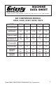
MACHINE DATA SHEET Customer Service #: (570) 546-9663 • To Order Call: (800) 523-4777 • Fax #: (800) 438-5901 AIR COMPRESSOR MODELS G0464, G0465, G0467, G0468, G0470 MODEL G0464 G0465 G0467 G0468 G0470 HORSEPOWER 11⁄2 11⁄2 21⁄2 11⁄2 2 AMPERAGE 8A 8A 14.5A 8A 14A TANK VOLUME 1.59 gal. 3.17 gal. 6.34 gal. 1.59 gal. 4.23 gal. MAXIMUM PSI 125 125 125 115 125 CFM @40 PSI 3.1 3.1 4.9 2.9 4.5 CFM @90 PSI 2.2 2.2 4 2.1 3.6 SHIPPING WEIGHT 39.7 lbs. 44.1 lbs. 62.8 lbs.
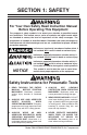
SECTION 1: SAFETY For Your Own Safety Read Instruction Manual Before Operating This Equipment The purpose of safety symbols is to attract your attention to possible hazardous conditions. This manual uses a series of symbols and signal words which are intended to convey the level of importance of the safety messages. The progression of symbols is described below. Remember that safety messages by themselves do not eliminate danger and are not a substitute for proper accident prevention measures.
. KEEP CHILDREN AND VISITORS AWAY. Keep all children and visitors a safe distance from the work area. 8. MAKE WORKSHOP CHILD PROOF. Use padlocks, master switches, and remove start switch keys. Shut off air supply before leaving shop. 9. NEVER LEAVE UNATTENDED TOOL CONNECTED TO AIR. DO NOT leave before relieving the tool of air pressure and disconnecting it from the air hose. 10. DO NOT USE IN DANGEROUS ENVIRONMENTS. DO NOT use in damp, wet locations, or where flammable or noxious fumes may exist. 11.
Additional Safety Instructions for Air Compressors 1. AIR NOZZLE. Never aim an air nozzle directly at yourself or others. Compressed air can break the skin, or enter the bloodstream through soft tissue or a cut, and cause a stroke or death. 6. COMPRESSED AIR USE. Do not use the compressor for filling breathing or diving tanks. Compressed air from this compressor cannot be used for pharmaceutical, food or health applications. 2. AIR COMPRESSOR STORAGE. DO NOT store the compressor while plugged into power.
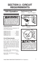
SECTION 2: CIRCUIT REQUIREMENTS 110V Operation Plug/Receptacle Type Plug Type ..............NEMA 5-15 (Figure 1) Serious personal injury could occur if you connect the machine to the power source before you have completed the set up process. DO NOT connect the machine to the power source until instructed to do so. Amperage Draw The motors on the air compressors will draw the following amps: G0464 Motor Draw ...................... 8 G0465 Motor Draw ...................... 8 G0467 Motor Draw ..............
Grounding Extension Cords In the event of an electrical short, grounding reduces the risk of electric shock. The grounding wire in the power cord must be properly connected to the grounding prong on the plug; likewise, the outlet must be properly installed and grounded. All electrical connections must be made in accordance with local codes and ordinances. The use of extension cords can cause power loss and overheating in air compressors.
SECTION 3: SET UP Unpacking Your air compressor left our warehouse in a carefully packed crate or box. If you discover the air compressor is damaged after you have signed for delivery, please immediately call Customer Service at (570) 5469663 for advice. Save the container and packing materials for possible inspection by the carrier or its agent. Otherwise, filing a freight claim can be difficult. Assembly NOTICE This machine should never be run without a full oil reservoir.
Placement When determining where to set up the air compressor in the shop or when taking the air compressor to a job site, an important consideration is access to an adequate and properly fused power supply. Refer to SECTION 2: CIRCUIT REQUIREMENTS for the needs of your particular compressor. Place the compressor on a solid and level surface. Make sure that the hoses attached to your pneumatic device are unrestricted in movement and not subject to being run over by vehicles or punctured by sharp objects.
SECTION 4: OPERATIONS Operation Safety Starting To start the air compressor: 1. Place the compressor on a solid, level surface with access to a properly fused power supply. DO NOT operate the compressor in an environment where there are explosive, flammable, or caustic fumes or gases. Long term exposure to this machine may cause hearing loss. To protect your hearing, always wear ANSI approved ear protection when operating this air compressor. 2.
6. Close the drain valve (Figure 5) to allow the tank to build up pressure. Line Pressure Regulation The tank pressure is displayed on the left pressure gauge, and the air to be delivered to the tool (line pressure) is displayed on the right pressure gauge, shown in Figure 6. Figure 5. Drain valve. 7. Check the tank pressure gauge (Figure 6) to see that the tank pressure climbs to approximately 115-120 PSI (around 8 BAR), then automatically turns OFF.
Connecting Tools 3. Connect an air line with a 1⁄4" NPT plug to the quick-connect coupler on the air compressor shown in Figure 8. When choosing air tools, consider the amount of air used (cubic feet per minute or CFM) by the tool. Nailers and staple guns have a low CFM requirement because they use air in short bursts. A paint sprayer or a pneumatic grinder uses a more continuous stream of air requiring a high CFM.
Storage When storing your air compressor, follow these guidelines: 1. Turn the compressor switch lever to OFF. Failure to unplug the air compressor before storage may result in the compressor running continuously, causing overheating, damage to the compressor, and possibly a fire. 2. Unplug the compressor. 3. Turn the regulator counterclockwise to set the line pressure to zero. 4. Run the air tool to relieve the air pressure in the hose, then remove the air hose and the tool.
SECTION 5: MAINTENANCE Schedule If the compressor is used on a daily basis, perform the following checks each week. Weekly 1. Blow dirt and dust off of the air filter (Figure 9), then re-install. Operating this equipment has the potential to cause eye injury and hearing loss. Always wear eye and ear protection when operating an air compressor. Be certain the safety protection you wear meet the appropriate standards of the American National Standards Institute (ANSI).
Monthly After the first 50 working hours or 30 days, perform the following maintenance: 1. Change the oil in the air compressor pump as described in Changing Oil on Page 19. Pressure Safety Valve Quarterly The pressure safety valve prevents damage to the tank by releasing pressure when the tank reaches maximum capacity. After every 300 working hours or 3 months, perform the following maintenance: To check the pressure safety valve: 1.
SECTION 6: SERVICE This section is provided for your convenience—it is not a substitute for the Grizzly Service Department. If you need help troubleshooting, replacing parts, or you are unsure of how to perform the procedures in this section, then feel free to call our Technical Support at (570) 546-9663. Troubleshooting Symptom Possible Cause Possible Solution Motor will not start. 1. Tank already pressurized. 1. Motor will not start if tank is fully pressurized. 2. Wait for motor to cool. 2.
Symptom Possible Cause Possible Solution Loud repetitious noise coming from machine. 1. Pulley setscrews or keys are missing or loose. 1. Inspect keys and setscrews. Replace or tighten if necessary. 2. Adjust fan cover mounting position, tighten fan, or shim fan cover. 2. Motor fan is hitting the cover. Low pressure at the tool. 1. Pressure regulator. 2. Air leaks in hoses. 3. Pressure gauge bad. 4. Pressure switch turns the motor OFF too soon.
Symptom Possible Cause Possible Solution Air leaks from pressure switch. 1. Faulty check valve. 1. Repair the check valve (see Page 19). 2. Replace pressure switch. 2. Faulty pressure switch. Air is dirty or has excessive moisture. 1. Tank is not drained. 2. Delivery pipes are dirty. Changing Oil Change the oil in the air compressor pump after the initial 50 hours, or 30 days of use; and every 300 hours, or 3 months after the first oil change.
3. Inspect the O-ring and diaphragm (Figure 14) for damage and dirt. Fixing Air Leaks Diaphragm Air leaks will cause low air output and increase the time the compressor must run. O-ring To find air leaks: 1. Turn the compressor OFF when the tank is fully pressurized and unplug the compressor. Figure 14. Check valve diaphragm and spring. 4. Replace any damaged parts and clean any dirt off of the diaphragm and Oring. 5. Re-assemble the check valve.
Pressure Switch The pressure switch has been factory set for the highest PSI that is safe for this compressor. 5. Turn the black plastic pressure adjustment screw (Figure 16) a half turn clockwise to increase the tank pressure and a half turn counterclockwise to decrease the pressure. The pressure switch ensures the pump will shut OFF when the air compressor tank reaches maximum PSI. NOTICE This air compressor has been factory set to turn ON and OFF at the proper PSI range.
G0464 Parts Breakdown �� �� �� �� �� � � � � � � � � �� � � �� �� �� �� �� �� �� �� �� �� �� �� �� �� �� �� �� �� �� �� �� �� �� �� �� �� �� �� �� �� �� �� �� �� �� �� �� �� �� �� �� �� -22- �� �� �� �� �� �� �� �� �� �� �� �� �� �� � �� �� �� �� � �� �� �� �� �� �� �� �� �� Model G0464/G0465/G0467/G0468/G0470 Air Compressors
G0464 Parts List REF PART # DESCRIPTION REF PART # DESCRIPTION 1 2 3 4 5 6 7 8 9 10 11 12 13 14 15 16 17 18 19 20 21 22 23 24 25 26 27 28 29 30 31 32 33 34 35 36 37 38 39 CAP SCREW M6-1 X 30 LOCK WASHER 6MM CYLINDER HEAD EXHAUST ELBOW GASKET VALVE PLATE VALVE REED GASKET LOWER PISTON GASKET LOWER CYLINDER CAP SCREW M6-1 X 20 GASKET LOWER COMPRESSION RING OIL RING PISTON PIN PIN CLIP CONNECTING ROD ECCENTRIC HEX NUT M6-1 OIL FILL CAP FLAT WASHER 5MM CAP SCREW M5-.
G0465 Parts Breakdown � �� � �� � �� � �� �� � � � � � �� �� �� �� � �� �� �� �� � �� �� �� �� �� �� �� �� �� �� �� �� �� �� �� �� �� �� �� �� �� �� �� �� �� �� �� �� �� �� �� �� �� �� �� �� �� �� �� �� �� -24- �� �� �� �� �� �� �� ���� �� �� �� �� �� �� �� �� �� �� �� �� �� ���� �� �� �� �� �� �� �� �� �� �� �� Model G0464/G0465/G0467/G0468/G0470 Air Compressors
G0465 Parts List REF PART # DESCRIPTION REF PART # DESCRIPTION 1 2 3 4 5 6 7 8 9 10 11 12 13 14 15 16 17 18 19 20 21 21-1 22 23 24 25 26 27 28 29 30 31 32 33 34 35 36 37 38 39 40 41 CAP SCREW M6-1 X 30 LOCK WASHER 6MM CYLINDER HEAD EXHAUST ELBOW 3/8 X 3/8 GASKET VALVE PLATE VALVE REED GASKET LOWER PISTON GASKET UPPER CYLINDER CAP SCREW M6-1 X 20 GASKET LOWER COMPRESSION RING OIL RING PISTON PIN CLIP PIN CONNECTING ROD ECCENTRIC HEX NUT M6-1 OIL FILLER CAP O-RING HEX BOLT M5-0.
G0467 Parts Breakdown � �� � � � �� �� � � � �� � �� �� �� �� �� �� � �� �� �� �� �� �� �� �� �� �� �� �� �� �� �� �� �� �� �� �� �� �� �� �� �� �� �� �� -26- �� �� �� �� �� �� �� �� �� �� �� �� �� �� �� �� �� �� �� �� �� �� �� �� �� �� �� �� �� �� �� �� �� �� �� �� �� �� �� �� �� Model G0464/G0465/G0467/G0468/G0470 Air Compressors
G0467 Parts List REF PART # DESCRIPTION REF PART # DESCRIPTION 1 2 3 4 5 6 7 8 9 10 11 12 13 14 15 16 17 18 19 20 21 22 23 24 25 26 27 28 29 30 31 32 33 34 35 36 37 38 39 40 41 42 43 HEX BOLT M8-1.25 X 10⁵ LOCK WASHER 8MM CYLINDER HEAD EXHAUST ELBOW CYLINDER GASKET VALVE PLATE PHLP HD SCR M4-.
G0468 Parts Breakdown � � �� � �� � �� � � �� � �� �� �� � � �� �� �� �� � �� � �� �� �� �� �� �� �� �� �� �� �� �� �� �� �� �� ���� �� �� �� �� �� �� �� �� �� �� �� �� �� �� �� �� �� �� �� �� �� �� �� �� �� �� �� �� �� �� �� �� �� �� �� �� -28- �� �� �� �� �� �� �� �� �� �� Model G0464/G0465/G0467/G0468/G0470 Air Compressors
G0468 Parts List REF PART # DESCRIPTION REF PART # DESCRIPTION 1 2 3 4 5 6 7 8 9 10 11 12 13 14 15 16 17 18 19 20 21 22 23 24 25 26 27 28 29 30 31 32 33 34 35 36 37 38 CAP SCREW M6-1 X 80 LOCK WASHER 6MM CYLINDER HEAD GASKET VALVE PLATE VALVE REED GASKET UPPER GASKET LOWER CYLINDER CAP SCREW M6-1 X 20 CAP SCREW M6-1 X 15 COVER COMPRESSION RING CONNECTING ROD BALL BEARING 6202 ECCENTRIC HEX NUT M6-1 COVER HEX BOLT M5-.8 X 16 CRANKCASE CAPACITOR 200 MFD CAPACITOR 40 MFD FLAT WASHER 8MM HEX NUT M8-1.
G0470 Parts Breakdown � � � �� � � � � �� � �� �� �� �� �� �� � �� �� �� �� � �� �� �� �� �� �� �� �� �� �� �� �� �� �� �� �� �� �� �� �� �� �� �� �� �� �� �� �� �� �� �� �� �� �� �� �� �� �� �� �� �� �� �� �� �� �� �� �� �� �� �� �� �� �� -30- �� Model G0464/G0465/G0467/G0468/G0470 Air Compressors
G0470 Parts List REF PART # DESCRIPTION REF PART # DESCRIPTION 1 2 3 4 5 6 7 8 9 10 11 12 13 14 15 16 17 18 19 20 21 22 23 24 25 26 27 28 29 30 31 32 33 34 35 36 37 HEX BOLT M6-1 X 55 LOCK WASHER 6MM CYLINDER HEAD EXHAUST ELBOW CYLINDER HEAD GASKET VALVE ASSEMBLY VALVE PLATE VALVE PATCH PISTON CYLINDER GASKET CYLINDER CAP SCREW M8-1.
WARRANTY AND RETURNS Grizzly Industrial, Inc. warrants every product it sells for a period of 1 year to the original purchaser from the date of purchase. This warranty does not apply to defects due directly or indirectly to misuse, abuse, negligence, accidents, repairs or alterations or lack of maintenance.
WARRANTY CARD Name _________________________________________________________________ Street _________________________________________________________________ City _______________________ State _________________________ Zip _________ Phone # ____________________ Email ________________________ Invoice # _____ Model # ____________________ Order # _______________________ Serial # ______ The following information is given on a voluntary basis.
Send a Grizzly Catalog to a friend: Name________________________________ Street________________________________ City______________State______Zip_______ FOLD ALONG DOTTED LINE Place Stamp Here GRIZZLY INDUSTRIAL, INC. P.O.