MODEL G0484 GEARHEAD MILL/DRILL WITH STAND OWNER'S MANUAL COPYRIGHT © APRIL, 2007 BY GRIZZLY INDUSTRIAL, INC., REVISED JANUARY, 2008 (TS) WARNING: NO PORTION OF THIS MANUAL MAY BE REPRODUCED IN ANY SHAPE OR FORM WITHOUT THE WRITTEN APPROVAL OF GRIZZLY INDUSTRIAL, INC.
����������������������������������������������������������������������� �������������������������������������������������������������� ���������������������������������������������������������������������� �������������������������������������������������������������������� ������������������������ ������������������������������������������������������������������ �������������������������������������������������������������������� ����������������������������������������������������������������� ����������
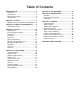
Table of Contents INTRODUCTION ............................................... 2 Foreword ........................................................ 2 Contact Info ................................................... 2 Machine Data Sheet ...................................... 3 Identification ................................................... 5 SECTION 1: SAFETY ....................................... 6 Additional Safety Instructions for Mill/Drills.... 8 SECTION 2: CIRCUIT REQUIREMENTS ........
INTRODUCTION Foreword Contact Info We are proud to offer the Model G0484 Gearhead Mill/Drill with Stand. This machine is part of a growing Grizzly family of fine metalworking machinery. When used according to the guidelines set forth in this manual, you can expect years of trouble-free, enjoyable operation and proof of Grizzly’s commitment to customer satisfaction.
Machine Data Sheet ������������� ����� ������������������������������������������������������������������������������������������ ��������������������������������� ������������������� ���������������������������������������������������������������������������������������������������������������������������������������������������������������������������������� ���������������������������������������������������������������������������������������������������������������������������������������������������
������������� ������������������������������������������������������������������������������������������������������������������������������������������������������������������ ��������� ��������������������������������������������������������������������������������������������������������������������������������������������������������������� ��������� �����������������������������������������������������������������������������������������������������������������������������������������������������������
Identification A W V B Y C X D U E T S F R N Q O P M G L K H J I Figure 1. G0484 Identification. A. B. C. D. E. F. G. H. I. J. K. L. M. Mill/Drill Motor Headstock Lift Motor Fine Feed Knob Headstock Tilt Lock Bolt and Scale Quill Feed Lever Fine Feed Lock Knob Manual Headstock Crank Y-Axis Handwheel X-Axis Handwheel Power Feed Rapid Feed Switch Power Feed Power Switch Power Feed Speed Dial Power Feed Direction Lever G0484 Gear Head Mill/Drill N. O. P. Q. R. S. T. U. V. W. X. Y.
����������������� �������������������������������������� ������������������������������������ �������������������������������������������������������������������������������������������������� �������������������������������������������������������������������������������������������� �������������������������������������������������������������������������������������������� �������������������������������������������������������������������������������������������� �������������������� �������������������
��������������������������������� ��� ����� ������ �������� ���� ����� ����� ����������� ���������� ��� �������� ����������� ����� ������ �������������������������������������������� ����������� ��� ��������������������������������� ����� ���� ��������� ���� ��������� �� ����� ���� ������������������������� ���� ����� ��������� ������������ ���� ���������� ������� ���������� ���� ������� ������������������ ���� ������ ������ ����� �������� ��� �������������������������������������� ������� ������ ��� �����
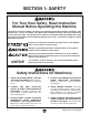
Additional Safety Instructions for Mill/Drills 1. UNDERSTANDING CONTROLS. Make sure you understand the use and operation of all controls before operating machine. 2. SAFETY ACCESSORIES. Always use a chip guard in addition to your safety glasses when milling to prevent bodily injury. 3. WORK HOLDING. Before starting the machine, be certain the workpiece has been properly clamped to the table. NEVER hold the workpiece by hand when using the mill/drill. 4. CHUCK KEY SAFETY.
Circuit Requirements SECTION 2: CIRCUIT REQUIREMENTS 220V Single-Phase Serious personal injury could occur if you connect the machine to the power source before you have completed the set up process. DO NOT connect the machine to the power source until instructed to do so. Grounding In the event of an electrical short, grounding reduces the risk of electric shock.
SECTION 3: SETUP Setup Safety This machine presents serious injury hazards to untrained users. Read through this entire manual to become familiar with the controls and operations before starting the machine! Wear safety glasses during the entire set up process! The Model G0484 is a heavy machine. Serious personal injury may occur if safe moving methods are not used. To be safe, get assistance and use power equipment to move the shipping crate and remove the machine from the crate.
Inventory Clean Up Inventory After all the parts have been removed from the crate, you should have the following items with your machine: Inventory: (Figure 3) Qty A. Downfeed Handles ..................................... 3 B. Face Mill Assembly R8............................... 1 C. Adapter R8 - JT3 ........................................ 1 D. Headstock Elevation Crank ........................ 1 E. Wrench 24mm ............................................ 1 F. Hex Wrenches, 4, 5, 6 mm ..................
Site Considerations Site Considerations Floor Load Refer to the Machine Data Sheet on Page 3 for the weight and footprint specifications of your machine. Some residential floors may require additional reinforcement to support both the machine and operator. Placement Location Consider existing and anticipated needs, size of material to be processed through each machine, and space for auxiliary stands, work tables, other machinery, and the operator when establishing a location for your new machine.
Mounting to Shop Floor Mounting to Shop Floor We recommend that you mount your new machine to the floor. Because floor materials may vary, floor mounting hardware is not included. Assembly To assemble your mill/drill: 1. Lag shield anchors with lag bolts and anchor studs (Figure 7) are two popular methods for anchoring an object to a concrete floor. Place the handwheels on the longitudinal and cross lead screws, and tighten the set screw (see Figure 8).
Test Run 5. Once the assembly is complete, test run your machine to make sure it runs properly and is ready for regular operation. The test run consists of verifying the following: 1) The main motor powers up and runs correctly and 2) the stop button safety feature works correctly. ����� �������� ��������� If, during the test run, you cannot easily locate the source of an unusual noise or vibration, stop using the machine immediately, then review Troubleshooting on Page 26.
Break-In After successfully completing the Test Run, it is necessary run the mill/drill in each speed and direction without a load to seat the bearings. NOTICE Only change spindle speed when the spindle is stopped. Attempting to change spindle speeds when the spindle is in motion will damage the drive gears and bearings. 3. Twist the emergency stop button clockwise so that it pops out. 4. Switch the spindle rotation dial to "F" (forward) and let the spindle run for 10 minutes. 5.
SECTION 4: OPERATIONS Control Panel Operation Safety A. Power Lamp: Glows when the master power switch is ON. Damage to your eyes and lungs could result from using this machine without proper protective gear. Always wear safety glasses and a respirator when operating this machine. B. Headstock Up Button: Controls the headstock motor so the headstock is powerfed upwards. C. Headstock Down Button: Controls the headstock motor so the headstock is powerfed downwards. D.
Spindle Height Control Table Travel (X-Axis and Y-Axis) Spindle height is changed by unlocking the quill lock lever and the fine feed knob, and using the quill feed handles or the fine feed knob (Figure 12). The spindle scale indicates the spindle height in inches and millimeters. Longitudinal Feed The longitudinal feed, or X-axis, is moved by the handwheel at the right end of the table. The handwheel will move the table in both directions side-to-side.
Tooling Changes Drawbar Nut Your mill/drill has an R-8 spindle taper. Follow these general procedures to install and remove R-8 tooling like drill chuck arbors, face cutters, or collets of your choice. LACERATION HAZARD! Leading edges of end mills and other cutting tools can be very sharp. Protect your hands with gloves or a shop towel when handling. Figure 14. Unseating the arbor/cutter. 6. Clear away all items from the cutter before turning the mill/drill ON.
Choosing Spindle RPM 2. Measure the diameter of your cutting tool in inches. 3. Use the following formula to determine the needed RPM for your operation: NOTICE Never shift gears while mill/drill or mill is running; otherwise, the gear teeth will be chipped or broken. To determine and set the mill to the needed cutting RPM: 1. Select the cutting speed required for the material of your workpiece using the table in Figure 15.
Milling/Drilling To mill a workpiece: 1. 2. Learn about the control panel shown on Page 16 and the controls shown in Figure 16. Failure to follow RPM and Feed Rate Guidelines may threaten operator safety from ejected parts or broken tools. Spindle Scale Quill Feed Lever Clamp the workpiece to the milling table, and adjust the headstock to the needed height, depth of cut, and milling path.
ACCESSORIES SECTION 5: ACCESSORIES H2689—R-8 Quick Change Collet Set An affordable quick change collet system with ultra precision. These spring collets are hardened and ground to exacting tolerances and offer incredible holding power. This set includes an R-8 arbor and nut, spanner wrench, plastic carrying case and collets sized 1⁄ 8", 1⁄4", 3 ⁄ 8", 1⁄ 2", 5 ⁄ 8", 3 ⁄4", 7⁄ 8", and 1". What's more, the nut features a self-ejecting rim! A set like this will truly speed up any tool changing process.
G9760—20-PC. 2 & 4 Flute TiN End Mill Set. Includes these sizes and styles in two and four flute styles: 3/16", 1/4", 5/16", 3/8", 7/16", 1/2", 9/16", 5/8", 3 /8", 11/16", and 3/4". G5641—1-2-3 Blocks G9815—Parallel Set H5556—Edge Finder Set G5641 G9815 Figure 23. G9760 20-PC End Mill Set. G9765—9-PC. Ball End Mill Set Features 2 flute ball nose end mills. Includes the following sizes: 1/8", 3/16", 1/4", 5/16", 3/8", 7/16", 1/2", 5/8" and 3/4". Figure 26.
SECTION 6: MAINTENANCE Always disconnect power to the machine before performing maintenance. Failure to do this may result in serious personal injury. Schedule Cleaning and Protecting Metal chips left on the machine that have been soaked with water-based coolant will invite oxidation and a gummy residue build-up around the moving parts. Use a brush and shop vacuum to remove chips and debris from the working surfaces of the mill.
Lubrication Ball Oilers Lubricate both ball oilers every 8 hours (see Figures 28–29). Use a manual oiler (oil can) filled with ISO 68 or SAE 20W non-detergent oil. To lubricate ball oilers, depress the ball with the tip of the oil can nozzle and squirt a little oil inside the fitting. Make sure to clean the outside of the ball oiler before and after each use to keep out contaminants. Figure 29. Cross slide ball oiler. Ways Clean the longitudinal, cross, and headstock ways of all debris.
Headstock Lead Screw Headstock Gearbox Oil On an annual basis, or every six months under heavy use, we recommend that you clean and lubricate the headstock lead screw with white lithium grease. On an annual basis, or every six months under heavy use, we recommend that you drain and refill the headstock oil with a 10-30W non-detergent oil. To clean and lubricate the lead screw: To change the headstock oil: 1. DISCONNECT MACHINE FROM POWER! 1. DISCONNECT MACHINE FROM POWER! 2.
Troubleshooting SECTION 7: SERVICE Review the troubleshooting and procedures in this section to fix or adjust your machine if a problem develops. If you need replacement parts or you are unsure of your repair skills, then feel free to call our Technical Support at (570) 546-9663. Troubleshooting Motor & Electrical Symptom Possible Cause Possible Solution Motor will not start. 1. 2. 3. 4. 1. 2. 3. 4. 5. 6. 7. 8. 9. Incorrect mill/drill operation. Main power panel switch is OFF.
Adjusting Gibs Longitudinal Gib Adjusting Screw The gibs control the accuracy of the table and headstock movement. During the life of your mill/ drill, you may have to adjust the gibs to remove looseness that is a result of normal wear. The goal of gib adjustment is to remove unnecessary looseness without causing the dovetail slides to bind. Loose gibs may cause poor finishes on the workpiece and may cause undue wear on the slides; over-tightening may cause pre-mature wear.
G0484 Wiring Diagram 220V Single Phase �� �� �� �� �� ������� ����� �� ������� ����� � � � � � � �� � � � �� � � � � � � �� ��������� ������ �� �� � � ���������������������������� ��������������������������� ����������� ���� �� �� ���� ��������������� � � �� � ��� � �� � ��� � � � ��� ��� ��� � � ���� �� � � �� � ������ � � ������ ������� ����� ��� �� �� �� � � ���������� ���������� �������� ��������� ������ ������ ��������� ������������ ������������ ��
Electrical Component Index Page 31, Figure 39. ELECTROCUTION HAZARD! Page 30, Figure 34. Page 30, Figure 36. Always disconnect power to the machine before beginning any electrical procedures. Ignoring this warning may result in fire or electrocution! Figure 1. Mill/drill front left view. Page 30, Figure 38. Page 30, Figure 37. Page 31, Figure 39. Page 31, Figure 35. Figure 2. Mill/drill right rear view.
Figure 36. Master power switch. Figure 34. Spindle motor rotary switch, left and right view. Figure 37. Spindle motor capacitors and wiring connections. Figure 35. Lift motor capacitor and wiring box. -30- Figure 38. Lift motor junction box.
l ica ectr l E n Mai Box er form s n Tra tion unc rd J r a te Mas inal Bo m Ter or Mot Lift or KM2 ct onta Up otor M t Lif utton B or Mot Lift Button n Dow C op or Mot Lift or KM1 tact Con St ncy e g r Eme Button Figure 39. Main wiring box.
Table Parts Breakdown �� �� � �� �� �� �� �� �� �� �� �� �� �� �� �� �� �� �� �� �� �� �� �� �� � � �� �� �� � � � � � �� �� � � � �� �� �� �� �� �� �� � � �� �� � � � �� � � � �� �� � � �� �� �� �� �� �� -32- G0484 Gear Head Mill/Drill
Table Parts List REF PART # DESCRIPTION REF PART # DESCRIPTION 1 2 3 4 5 6 7 8 9 10 11 12 13 14 15 16 17 18 19 20 21 22 P0484001 P0484002 PSS03M P0484004 P0484005 P0484006 P0484007 P0484008 P0484009 PSB14M P0484011 P0484012 P0484013 P0484014 PSB33M P0484016 P0484017 P0484018 PS17M P0484020 P0484021 PW06M HANDLE HANDWHEEL SET SCREW M6-1 X 8 PIN HANDWHEEL CLUTCH GRADUATED DIAL KNOB M5-.8 X 12 SHIFTING RING THRUST BEARING 17 X 30 X 9MM CAP SCREW M8-1.
Column Parts Breakdown ��� ��� ��� ��� ��� ��� ��� ��� ��� ����� ��� ��� ��� ��� ��� ��� ��� ��� ��� ��� ��� ��� ����� ����� ��� ��� ��� ��� ����� ��� ��� ��� ��� ��� ��� ��� ��� ��� ��� ��� ��� ��� ��� ��� ��� ��� ��� ��� ��� ��� ��� ��� ��� ��� -34- G0484 Gear Head Mill/Drill
Column Parts List REF PART # DESCRIPTION REF PART # DESCRIPTION 101 102 103 104 105 106 107 108 109 110 111 112 113 114 115 115-1 115-2 115-3 115-4 116 117 118 119 120 121 122 PB06M P0484102 P0484103 P0484104 P0484105 P0484106 PSB26M P0484108 PLW10M PB80M P0484111 PS37M P0484113 PSB01M P0484115 P0484115-1 P0484115-2 P0484115-3 P0484115-4 PSB06M PK01M P0484118 P0484119 PSS03M P0484121 P0484122 HEX BOLT M8-1.
HEAD A Head Parts Breakdown, Part A ��� ��� ��� ��� ��� ��� ��� ��� ��� ��� ����� ��� ��� ����� ����� ����� ����� ����� ��� ����� ����� ��� ����� ����� ����� ����� ��� ��� ��� ��� ��� ��� ��� ��� ��� ��� ����� ��� ��� ����� ��� ��� ��� ��� ��� ��� ��� ��� ��� ��� ��� ��� ��� ��� ��� ��� ��� ����� ����� ��� ��� ��� ��� ��� ��� ��� ��� ��� ��� ��� ��� ��� ��� ��� ��� ��� ��� ��� ��� ��� ��� ��� ��� ��� ��� ��� ��� ��� ��� ��� ��� ��� ��� ��� ��� ��
G0484 Gear Head Mill/Drill ��� ��� ��� ��� ��� ��� ��� ��� ��� Page 36 � ��� ��� ��� ��� ��� ��� ��� ��� ��� ��� ��� ��� ��� ��� ��� HEAD B Head Parts Breakdown, Part B -37-
Head Parts List REF PART # DESCRIPTION REF PART # DESCRIPTION 201 201-1 201-2 201-3 201-4 201-5 201-6 201-7 202 203 204 205 206 207 208 209 210 211 212 213 214 215 216 217 218 219 220 221 222 223 224 225 226 227 228 229 230 231 232 233 234 235 236 237 238 239 240 241 242 243 MOTOR 1-1/2HP 220V/60HZ/1-PH MOTOR JUNCTION BOX COVER MOTOR JUNCTION BOX CAPACITOR CD60 150MFD/250VAC CAPACITOR CBB60 20MFD/450VAC TERMINAL BLOCK MOTOR FAN COVER MOTOR FAN CAP SCREW M10-1.
Head Parts List REF PART # DESCRIPTION REF PART # DESCRIPTION 285 286 287 288 289 290 291 292 293 294 295 296 297 298 299 300 301 302 303 304 P0484285 P0484286 P0484287 PS17M P0484289 P0484290 P0484291 P0484292 P0484293 P0484294 P0484295 PN01M PW03M PB39M P0484299 P0484300 P0484301 PFH19M P0484303 P0484304 FEED BASE SHAFT PIN PHLP HD SCR M4-.
Label Placement 406 401 405 402 404 403 407 REF PART # DESCRIPTION REF PART # 401 402 403 404 SAFETY GLASSES LABEL READ MANUAL LABEL MODEL NUMBER LABEL MACHINE ID & CONTROL PANEL LABEL 405 406 407 PLABEL-11 PLABEL-12 P0484327 P0484328 DESCRIPTION PLABEL-14 ELECTRICITY LABEL P0484330 CUTTING/DAMAGE LABEL PPAINT-1 GRIZZLY GREEN TOUCH UP PAINT Safety labels warn about machine hazards and ways to prevent injury.
WARRANTY AND RETURNS Grizzly Industrial, Inc. warrants every product it sells for a period of 1 year to the original purchaser from the date of purchase. This warranty does not apply to defects due directly or indirectly to misuse, abuse, negligence, accidents, repairs or alterations or lack of maintenance.
������������� ���������������������������������������������������������������������������������� � ������������������������������������������������������������������������������������ ����� ����������������������� ������������������������������� ���� ��������������������� ���������������������������� ������ ������������������������ ��������������������������� ���������������������������� ������������������������������� ��������������������������� �������������������������������������������������������������
���������������������� ����� ����� ���� ������������������������ ������������� �������������������������� ���������������������� ����������������������������������� ����������������������������������� ������������������������������������� �������������������������������������� ��������������������������������������
����������������������������������������������������������������������� ������������������������������������� ������������������������������������ ����������������� �������������������������������� ��������������������������������� ���� ��������������������� ������������������