MODEL G0486/G0487 DOUBLE-HEAD WIDE-BELT SANDER OWNER'S MANUAL COPYRIGHT © APRIL 2006 BY GRIZZLY INDUSTRIAL, INC. WARNING: NO PORTION OF THIS MANUAL MAY BE REPRODUCED IN ANY SHAPE OR FORM WITHOUT THE WRITTEN APPROVAL OF GRIZZLY INDUSTRIAL, INC.
����������������������������������������������������������������������� �������������������������������������������������������������� ���������������������������������������������������������������������� �������������������������������������������������������������������� ������������������������ ������������������������������������������������������������������ �������������������������������������������������������������������� ����������������������������������������������������������������� ����������
Table of Contents INTRODUCTION ............................................................................................................................... 3 Foreword .................................................................................................................................... 3 Contact Info ................................................................................................................................ 3 Control Panel Features .......................................
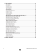
SECTION 7: SERVICE .................................................................................................................. 27 Table Calibration ...................................................................................................................... 27 Platen Service .......................................................................................................................... 27 Brake Service ................................................................................
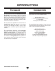
INTRODUCTION Foreword Contact Info We are proud to offer the G0486/G0487 Wide Belt Sander. This machine is part of a growing Grizzly family of fine woodworking machinery. When used according to the guidelines set forth in this manual, you can expect years of trouble-free, enjoyable operation and proof of Grizzly’s commitment to customer satisfaction.
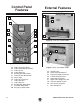
Control Panel Features External Features D E F A A B C H C I D J E K F L G M B Figure 2. Front View, Model G0487. H G I Figure 1. Control Panel, Model G0487. A. B. C. D. E. F. G. H. I. J. K. L. M. -4- Digital Amp Draw Meter Table-Height Digital Readout Table Up Key Table Down Key Sanding Belt Start Button Conveyor Belt Start Button Power Light Table Set (Enter) Key Table Start Key Table Stop Key Sanding Belt Stop Button Feed Belt Stop Button Emergency Stop Button Figure 3.
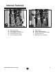
Internal Features J E A A I F B G H C B D D C Figure 4. Inside the left access door. A. B. C. D. E. Belt Tension Knob Platen Adjustment Lever Platen Adjustment Lock Lever Lock Post Release Lever Tracking Adjustment Knob G0486/G0487 Wide Belt Sander Figure 5. Inside the right access door. F. G. H. I. J.
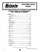
Machine Data Sheet (G0486) ������������� ����� ������������������������������������������������������������������������������������������ ���������������������������� ��������������������� ����������������������������������������������������������������������������������������������������������������������������������������������� �������������������� � ������������������������������������������������������������������������������������������������������������������������������������ � ��������������������
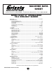
Machine Data Sheet (G0487) ������������� ����� ������������������������������������������������������������������������������������������ ���������������������������� ��������������������� ����������������������������������������������������������������������������������������������������������������������������������������������� �������������������� � ������������������������������������������������������������������������������������������������������������������������������������ � ��������������������
SECTION 1: SAFETY For Your Own Safety, Read Instruction Manual Before Operating this Machine The purpose of safety symbols is to attract your attention to possible hazardous conditions. This manual uses a series of symbols and signal words which are intended to convey the level of importance of the safety messages. The progression of symbols is described below. Remember that safety messages by themselves do not eliminate danger and are not a substitute for proper accident prevention measures.
Safety Instructions for Machinery 7. ONLY ALLOW TRAINED AND PROPERLY SUPERVISED PERSONNEL TO OPERATE MACHINERY. Make sure operation instructions are safe and clearly understood. 8. KEEP CHILDREN AND VISITORS AWAY. Keep all children and visitors a safe distance from the work area. 9. MAKE WORKSHOP CHILD PROOF. Use padlocks, master switches, and remove start switch keys. 10. NEVER LEAVE WHEN MACHINE IS RUNNING.
Additional Safety for Wide Belt Sanders 1. 2. INFEED/OUTFEED AREA. When feeding the workpiece into the machine, keep clear of kickback path. WORKPIECE FEEDING. Never force the workpiece into the sander, and feed only one workpiece at a time. 3. CLOTHING. Roll up or button sleeves, tie all loose clothing or hair so it will keep clear of entanglement hazards. 4. NARROW WORKPIECES. Never sand workpieces narrower than 3⁄16''. 5. THIN WORKPIECES. Never workpieces thinner than 3⁄16''. sand 6.
SECTION 2: CIRCUIT REQUIREMENTS 220V/440V Connection Hard wire this machine to a power panel that has proper overload protection and a locking shut-off lever (Figure 6). If you are unsure about electrical wiring, consult a qualified electrician before attempting any wiring. Amperage Loads The following list outlines the electrical phase and voltage required to operate the Model G0486/ G0487, as well as the amperage draw of their motors and circuit requirements.
440V Connection To connect this machine to 440V three-phase power, you must purchase two thermal overload relays. Each machine model requires unique relays, so refer to 440 Conversion Kits on Page 65 or the relay part numbers. 4. Refer to Figure 8 and find the power panel on your machine. 5. Swap out the applicable thermal relays and contactors from the conversion kit at the locations shown in Figure 8, and set them to the overload values listed.
SECTION 3: SET UP Unpacking Inventory Crate contents, (Figure 9). This sander is a heavy machine weighing over 4000 lbs (shipping weight). Personal injury can occur if the machine is moved without appropriate machinery. Use a crane or forklift when moving or lifting the machine. Your wide belt sander was carefully packed when it left our warehouse. If you discover the machine is damaged after you have signed for delivery, please immediately call Customer Service at (570) 546-9663 for advice.
Hardware Chart -14- G0486/G0487 Wide Belt Sander
Clean Up Any unpainted surfaces are coated with a waxy oil to protect them from corrosion during shipment. Remove this protective coating with a solvent cleaner or citrus-based degreaser such as Grizzly’s G7895 Degreaser. To clean thoroughly, some parts may need to be removed. For optimum performance from your machine, make sure you clean all moving parts or sliding contact surfaces that are coated. Avoid chlorine-based solvents as they will damage painted surfaces should they come in contact.
Beginning Assembly Complete the assembly in the order provided in this manual. Then read the rest of the manual before attempting any type of sanding operation. Your safety is important! Please follow the warnings below during this entire section: Disconnect power to the machine for the assembly process. Failure to do this may result in serious personal injury. Air Line Installation To install the air line: 1. Connect the hose from your air compressor to the air inlet (Figure 11) on the regulator.
Sanding Belt 5. To install the sanding belt: 1. DISCONNECT THE SANDER FROM THE POWER SOURCE AND REMOVE AIR PRESSURE COMPLETELY! 2. De-activate the belt tension piston by turning the belt tension knob (Figure 14). 3. Remove the lock post release lever (Figure 14) by turning it counterclockwise 1⁄2 turn and pulling it up and out of the mounting hole. 4.
Pressure Rollers The pressure rollers have been set at the factory, but for safety, you should verify that they are set below the level of the sanding roller. It is absolutely essential to keep the pressure rollers set below the level of the sanding roller. If the pressure rollers are even, or higher than the sanding roller, the wood WILL be propelled from the sander at a high rate of speed. This situation could cause serious kick-back injury.
To start the machine: 1. Wear safety glasses, hearing protection, and a respirator at all times when running the machine! 2. Connect the machine to the power source. 3. Press the TABLE UP and TABLE DOWN keys. The table should move up and down smoothly. Note: Make sure the table moves in the same direction as the button description. If not, then the power needs to be disconnected and any two power wires need to be switched at the circuit breaker in the electrical box.
SECTION 4: OPERATIONS Operation Safety Choosing Sandpaper Your safety is important! Please follow the warnings below during this entire section: The grit you choose will depend on the type of work, the species of wood and the stage of finishing. Below is a chart that groups abrasives into different categories and shows which grits fall into each one. We recommend using aluminum oxide sanding belts for the best results.
Table Movement Adjusting Feed Rate The table height can be adjusted manually or with the digital key pad and motor (see Figure 16). The dial attached to the side of the feed belt gear box (Figure 17) adjusts the feed rate of the sander. Manual Table Movement: Turn the handwheel located under the front of the infeed table for manual table positioning. Motorized Table Movement: Press the TABLE UP or TABLE DOWN key once for motorized table positioning in 0.005" (0.125mm) increments.
Amp Draw Meter The amperage draw meter (Figure 18) is located above the control panel. Use the meter to monitor the amperage draw on the machine while performing sanding operations. As a general rule, always start with a small load and work your way up. DO NOT work your machine to its maximum load, where you can hear the motor lose RPM; instead, make multiple passes or install a coarser grit paper.
Sanding Workpiece Platen Adjustment Typically, no more than 0.5mm (approx. 1⁄64") of material is removed during each pass. Attempts to remove too much material can cause jamming, wood burning, rapid sandpaper wear or tearing, poor finish, short motor life, and belt slippage. Your sander is equipped with an adjustable felt platen and graphite slip for those extra sensitive sanding operations. The platen position allows for 3 basic types of sanding.
SECTION 5: ACCESSORIES H3741—30 HP Rotary Phase Converter H3742—40 HP Rotary Phase Converter Add 3-phase, multi-motor capability to your singlephase electrical supply. Operate single or multiple motors, transformers, and resistance loads at 100% power and 95% efficiency while saving big dollars at cheaply metered, singlephase electrical rates. Complete step by step instructions are furnished along with complete wire and fusing requirements for various motor loads.
SECTION 6: MAINTENANCE General Your safety is important! Please follow the warnings below during this entire section: Weekly Grease the grease fittings located on the feed belt roller axles and the sanding belt roller axles with Gear Lube-2 (GL-2) or automotive grease. They are identified with yellow labels. Monthly Disconnect power to the machine when performing maintenance, assembly or adjustments. Failure to do this may result in serious personal injury.
Sanding Belts You can greatly increase the lifespan of your sanding belts if you clean them often. As mentioned on Page 24, cleaning pads are the fastest way to remove saw dust build-up. Air System The air system is durable and reliable; however, components do wear with age. If you suspect that an item in your air system may be having problems, see the Air System Diagram on Page 37. • Adjust regulator to 75 PSI. • Carefully inspect all air lines for cracks, tears or hardening. Replace faulty hoses.
SECTION 7: SERVICE Table Calibration NOTICE The digital thickness gauge has been calibrated at the factory and should require no further adjustment. However, we recommend verifying its accuracy. —If it does, the sander is properly calibrated and accurate to the nearest 0.005". —If it does not, you must recalibrate the digital thickness scale. To recalibrate the digital thickness scale: 1. Use the first board fed through the sander to test the accuracy of the digital thickness gauge.
Brake Service To replace the brake pads: 1. DISCONNECT THE SANDER FROM THE POWER SOURCE AND REMOVE AIR PRESSURE COMPLETELY! 2. Remove the nuts from the two mounting bolts and the two snap rings on the mounting pins behind the bracket. Eventually the brake pads will wear out. Checking and replacing these is a simple project that can be done in the shop, with the exception of having the rotor resurfaced on a lathe. 3.
Oscillation Timing 3. NOTICE The oscillation adjustments have been performed at the factory and should require no further attention. However, we recommend verifying the settings. An adequate stream of air through the air fork gap (Figure 27) is essential for proper oscillation. If the jet of air is weak through the gap, the belt will track away from the controller and into the limit switch on the opposite end of the roller.
5. Tighten the lock nut (Figure 28) to secure the airflow adjustment knob. 6. Restrict the airflow across the air fork gap with a scrap piece of wood. You should notice the roller pivot to the right. When the stick is removed, the roller should pivot back to the left. 7. Test the oscillation by running the sander. Make note of the time it takes for the belt to oscillate from left-to-right and from right-toleft.
Oscillation Speed The oscillation speed of the sanding belt is adjustable. Different oscillating speeds yield different sanding results. We recommend trying various speeds on a scrap piece of wood similar to the final workpiece. To adjust the oscillation speed: 1. Loosen the lock nut on the speed control adjustment knob (Figure 30). Lock Nut Table Parallelism NOTICE The table has been adjusted at the factory and should require no further attention.
Pressure Rollers To adjust the table parallelism: 1. Pass the widest size board your machine will allow through the sander until the entire surface of the board is making contact with the sanding belt. 2. Measure the thickness of the board at various points around the edge. 3. If there is a variation of thickness, the table can be adjusted accordingly. 4. DISCONNECT THE SANDER FROM THE POWER SOURCE! To adjust the pressure rollers: 1. DISCONNECT THE SANDER FROM THE POWER SOURCE! 2.
6. Loosen the infeed pressure roller lock nuts (Figure 34) on the infeed pressure roller. Turn the adjustment studs (Figure 34) to lower the infeed pressure roller until it just touches the board. Note: DO NOT continue to lower the roller beyond that point. Adjustment Stud V-Belt Adjustment To adjust either V-belt: 1. DISCONNECT THE SANDER FROM THE POWER SOURCE! 2. Loosen the lock nut (Figures 35 & 36). Roller Lock Nuts V-Belt Lock Nut Adjustment Nut Figure 34. Pressure roller adjustment location.
Conveyor Belt Replacement Tools Needed: Qty Make sure that you have a lifting device or another person to help in table removal. 9 mm Hex Wrench............................................. 1 19 mm Combination Wrench ............................. 1 12 mm Combination Wrench ............................. 1 14 mm Combination Wrench ............................. 1 #2 Phillips Screwdriver ..................................... 1 8' 2x4s ..............................................................
� ������������ ���������������� ����������� ���������� ���������� ������ ������ ����� � � � � � � � � �� ��������� ����������� ����� Figure 38. Conveyor belt removal sequence.
Feed Belt Tension Feed Belt Tracking Tools Needed: Qty Wrench or Socket 20mm ....................................1 Phillips Screwdriver #2 .......................................1 Tools Needed: Qty Hex Wrench 6mm ...............................................1 NOTICE To adjust the feed belt tension: Adjust the feed belt tension before adjusting the feed belt tracking. 1. DISCONNECT THE SANDER FROM THE POWER SOURCE! 2. Do not remove the safety guard! To adjust the feed belt tracking: 3.
Air System Diagram A. B. C. D. E. F. I. J. K. L. M. N. O. P. Q. R. Oscillation Timing Piston and Diaphragm Assy.
Review the troubleshooting and procedures in this section to fix your machine if a problem develops. If you need replacement parts or you are unsure of your repair skills, then feel free to call our Technical Support at (570) 546-9663. Troubleshooting Motor & Electrical Symptom Possible Cause Possible Solution 1. Limit switch or emergency stop is at fault. 1. Correct situation that caused limit switch to engage, reset the emergency stop button. 2. Check power line for proper voltage. 3.
Troubleshooting Symptom Possible Cause Possible Solution Lines across width of workpiece. 1. Sanding belt seam is open or damaged. 1. Repair or replace sanding belt. Glossy spots or streaks on workpiece. 1. Worn sanding belt. 2. Rear pressure roller too low. 1. Replace sanding belt. 2. Raise rear pressure roller. (See warning in Pressure Roller section, Page 18!) Sanding belt clogs quickly. 1. Sanding belt grit too small for particular job. 2. Excessive depth of cut. 3. Wood is too moist. 1.
Control Panel Component Locations (G0486/G0487) Digital Amp Draw Meter Digital Panel Sanding Belt START Button Conveyor Belt START Button Sanding Belt STOP Button Conveyor Belt STOP Button Emergency Stop Button Power Lamp -40- G0486/G0487 Wide Belt Sander
General Control Panel Electrical Diagram (G0486/G0487) �� �� �� �� �� �� � � � � � � �� �� � � �� �� �� �� �� �� �� �� � ����������������� ������������� �������������� � � ������������� � � ������ ������������� ������������� ������ � ������������ ���������� � � � �� � � �� � ���� ���� � � �� �� �� �� �� �� �� �� �� �� �� � ������������������� ������������� ���� � ���� � ��� �� �� � � � � � � � � � ��������������� ����������������� ������ � � � �� � � � � � ������������ ��
-42- � �� �� � � �� �� � �� �� � �� � �� �� �� � �� �� �� �� �� �� � �� �� � �� � �� � �� �� � �� � � �� � �� �� �� �� �� �� �� �� � � � � �� �� �� � �� � �� � ��� � � � � � � � � � � �� �� �� �� � �� � �������� � �� �� � � � ��� �� �� � � �� �� �� � � �� �� �� � �� �� �� � �� �� � � �� �� �� � � �� �� � � �� �� � �� �� �� �� �� �� �� � �� �� �� �� �� ����� �� ��� � � �� �� �� �� �� �� � �� �� �� �� � �� � �� �� � � �� � �
Wiring Box Components (G0486 220V/440V, G0487 440V) Emergency Brake Contactor Sanding Motor Contactor Conveyor Motor Contactor Transformer Amp Meter Current Sensor Fuses Sanding Motor Start Delay Sanding Motor Overload Relay Conveyor Motor Overload Relay G0486/G0487 Wide Belt Sander UP/DOWN Table Motor Contactors 220V ThreePhase Power Supply Junction Block -43-
-44- � �� � ��� � �� �� �� �� � �� ��� �� �� � �������� �� � � �� � �� �� � ��� �� �� ��� ����� �� ��� � ���� ��� �� �� �� �� �� ��� � �� �� �� �� � �� � ��� ��� � � � �� � �� � � �� � � �� � � � � � � ��� �� �� � ���� ���� ����� �� ��� � ���� ��� �� �� �� �� �� ��� � ����� �� � � �� � ��� �� ��� �� �� � � �� �� �� �� �� �� �� �� �� � �� �� �� �� �� �� ���� �� �� � �� � �� �� �� �� �� ����� �� ��� � ��� �� �� �� �� �� � �� �� �� �� �
Wiring Box Components (G0487 220V) Conveyor Motor Contactor Emergency Brake Contactor Table Up/Dwn Contactors Sanding Motor Contactors Sanding motor Start Delay Transformer Two 4 Amp Fuses Conveyor Motor Overload Relay Sanding Motor Overload Relay G0486/G0487 Wide Belt Sander Main Junction Block Amp Meter Current Sensor 220V/440V Three-Phase Power Supply Junction Block -45-
general electric diagram General Electric Diagram (G0486/G0487) � � � � ��� �� � �� �� � � � � ����� �������� ���� �� � � � �� �� � � � ����� ����� �� ��� �� � �������� �� � � � � � � � � � � ��� � �� ���� ���� � � � � � � � �� � � � � � � � � � � ����� � � ������� ���� � � � �� � � ��� � � �� �� � ���� ���� ���� � �� ��� �� �� � � ���� � � ����� ����� �� � ��� ���� ����� �������� ���� � ������������ ��� � ��� � ��� ��� ���� ���� ���� �
wiring box electrical diagram Motor Wiring (G0486/G0487) ������������� �������������������� �� �� �� �� �� �� �� �� �� �� �� �� �� �� �� � � � � � � �� �� �� �� �� �� �� �� �� � � � � � � ������������� ���������� ������������� ���������� ��������������������� ��������������������� �� �� �� �� �� �� �� �� �� �� �� �� �� �� �� �� �� �� ���������������� �� �� �� �� �� �� ���������������� �� �� �� ������������� ���������� G0486/G0487 Wide Belt Sand
Tool Box and Accessories Diagram 0000 Series Parts � � � � ��� � � � �� �� � �� ��� �� �� -48- G0486/G0487 Wide Belt Sander
Tool Box and Accessories Parts List REF PART # DESCRIPTION REF PART # DESCRIPTION 1 2 3 4 4 5 5 6 7-1 7-1 PLATEN REMOVAL TOOL CERAMIC LIMIT SWITCH POST TOOL BOX 44" PLATEN FELT (G0486) 52" PLATEN FELT (G0487) GRAPHITE 44" X 3.54" (G0486) GRAPHITE 52" X 3.
Sanding Motor System Diagram 1000 Series Parts ��� ��� ��� ��� ��� ��� ��� ��� ��� ��� ��� ��� ��� ��� ��� ��� ��� ��� ��� ��� ��� ��� ��� ��� ��� ����� ��� ��� ��� ����� ��� ��� ��� ��� ��� ��� ��� ��� ��� ����� ��� ��� ��� ��� ��� ��� ��� ��� ��� ��� ��� ��� ��� ��� ��� ��� ��� ��� ��� ��� ������ ������ -50- G0486/G0487 Wide Belt Sander
Sanding Motor System Parts List REF PART # DESCRIPTION REF PART # DESCRIPTION 101 101 102 102 103 104 105 106 107 108 109 109 109-1 109-1 109-2 109-2 110 111 112 113 114 115 116 117 118 119 121 122 123 124 125 126 P05811101 P04871101 P05811102 P04871102 P05811103 PN06 PH29331105 PLW07 PB41 PW01 P04861109 P04871109 P04861109-1 P04871109-1 P04861109-2 P04871109-2 P05811110 PSB11 PLW01 PH29331113 PB03 PLW01 PH29331116 PVB76 P05811118 PVA50 P04861121 PW02 PB21 P04861124 PSB05 P04861126 MACHINE FRAME (G0
Table Lift System Diagram 2000 Series Parts ��� ��� ��� ��� ��� ��� ��� ��� ��� ��� ��� ��� ��� ��� ��� ��� ��� ��� ��� ��� ��� ��� ��� ��� ��� ��� ��� ��� ���� ��� ��� ����� ����� ��� ��� ��� ��� ��� ��� ��� ��� ��� ��� ��� ��� ��� ��� ��� ��� ��� ��� ��� ��� ��� ��� ��� ��� ��� ��� ��� ��� ��� -52- ��� ��� ��� ��� ��� ��� ��� ��� ��� ��� ��� ��� ��� G0486/G0487 Wide Belt Sander
Table Lift System Parts List REF PART # DESCRIPTION REF PART # DESCRIPTION 101 102 103 104 105 106 107 108 109 110 111 111 201 202 203 204 206 207 301 302 303 304 305 306 307 308 309 310 311 312 313 314 315 316 317 318 ELEVATION SCREW HEX BOLT 5/16-18 X 1 FLAT WASHER 5/16 LOCK WASHER 5/16 LOCK WASHER 5/16 HEX BOLT 3/8-16 X 1 ELEVATION SLIDE DUST BOOT HEX BOLT 5/16-18 X 3/4 LOCK WASHER 5/16 CHAIN (G0486) CHAIN (G0487) NUT HOUSING NUT THRUST BEARING 51107 EXT RETAINING RING 35MM SPROCKET WHEEL NUT HOUSI
-54- ��� ��� ��� ��� ��� ��� ��� ��� ��� ��� ��� ��� ��� ��� ��� ��� ��� ��� ��� ��� ��� ��� ��� ��� ��� ��� ��� ��� ��� ��� ��� ��� ��� ��� ��� ��� ��� ��� ��� ��� ��� ��� ��� ��� ��� ��� ��� ��� ��� ��� ��� ����� ����� Conveyor System Diagram 3000 Series Parts G0486/G0487 Wide Belt Sander � � � � � � � �
Conveyor System Parts List REF PART # DESCRIPTION REF PART # DESCRIPTION 101 101 102 102 103 104 105 106 107 107 108 109 110 111 112 113 114 115 116 117 118 119 120 121 123 123-1 123-2 P05813101 P04873101 P05813102 P04873102 P04863103 P04863104 PLW04 PB18 P05813107 P04873107 PH29343108 P04863109 P04863110 P04863111 P0539326 PLW04 PB24 P04863115 P04863116 PB16 P04863118 PK66M PB07M PLW04M P05813123 P05813123-1 P05813123-2 CONVEYOR TABLE (G0486) CONVEYOR TABLE (G0487) CONVEYOR BELT (G0486) CONVEYOR BE
-56- ��� ��� ��� ��� ��� ��� ��� ��� ��� ��� ��� ��� ��� ��� ��� ��� ��� ��� ��� ��� ��� ��� ��� ��� ��� ��� ��� ��� ��� ��� ��� ��� ��� ��� ��� ��� ��� ��� ��� ��� ��� ��� ��� ��� ��� ��� ��� ��� ��� ��� ��� ��� ��� ��� ��� ��� ��� ��� ��� ��� ��� ��� ��� ��� Feed, Drum, and Pressure Roller Diagram 4000 Series Parts G0486/G0487 Wide Belt Sander
Feed, Drum, and Pressure Roller Parts List REF PART # DESCRIPTION REF PART # DESCRIPTION 103 107 108 109 201 201 202 202 203 204 205 206 301 COMPRESSION SPRING HEX NUT 3/8-16 HEX BOLT 5/16-18 X 1-1/4 LOCK WASHER 5/16 PISTON ROLLER SHAFT (G0486) PISTON ROLLER SHAFT (G0487) PISTON ROLLER (G0486) PISTON ROLLER (G0487) BALL BEARING 6001ZZ SHAFT BEARING COLLAR SET SCREW 1/4-20 X 1/2 PISTON ROLLER ASSEMBLY ADJUSTMENT KNOB 302 303 403 404 404 405 406 407 407 408 409 409 MIDDLE PISTON BRACKET ROLL PIN 3 X 24
-58- ��� ��� ��� ��� ��� ��� ��� ��� ��� ��� ��� ��� ��� ��� ��� ��� ��� ��� ��� ��� ��� ��� ��� ��� ��� ��� ��� ��� ��� ��� ��� ��� ��� ��� ��� ��� ��� ��� ��� ��� ��� ��� ��� ��� ��� ��� ��� ��� ��� ��� ��� ��� ��� ��� ��� ��� ��� ��� ��� ��� ��� ��� ��� ��� ��� ��� ��� ��� ��� ��� ��� ��� ��� ��� ��� ��� ��� ��� ��� ��� ��� ��� Sanding Drum and Platen Diagram 5000 Series Parts G0486/G0487 Wide Belt Sander
Sanding Drum and Platen Parts List REF PART # DESCRIPTION REF PART # DESCRIPTION 101 102 102 103 104 105 106 107 108 109 110 111 112 113 114 115 116 117 118 119 201 202 202 203 204 205 206 211 301 301 302 302 303 303 304 304 BEARING HOUSING RUBBER ROLLER (G0486) RUBBER ROLLER (G0487) FASTENING TUBE CYL.
Upper Roller System Diagram 6000 Series Parts ��� ��� ��� ��� ��� ��� ��� ��� ��� ��� ��� ��� ��� ��� ��� ��� ��� ��� ��� ��� ��� ��� ��� ��� ��� ��� ��� ��� ��� ��� ��� ��� ��� ��� ��� ��� ��� ��� ��� ��� ��� ��� ��� ��� ��� ����� ��� ��� ��� ��� ��� ��� ��� ��� ��� ��� ����� ��� ��� ��� ��� ��� ��� ����� ��� ��� ��� ��� ��� ��� ��� ��� ��� ��� ��� ��� ��� ��� ��� ��� ��� ��� ��� ��� ��� ��� ��� ����� ��� ����� ��� ����� ����� -60- G0486/G0487 Wide Belt Sander
Upper Roller System Parts List REF PART # DESCRIPTION REF PART # DESCRIPTION 101 101 101-1 101-1 102 102 102-1 102-1 103 103 103-1 103-1 104 104 104-1 104-1 105 106 107 108 109 110 111 112 113 114 115 115-1 116 116-1 117 118 119 120 121 122 123 124 125 126 127 128 129 130 SQUARE FRAME REAR (G0486) SQUARE FRAME REAR (G0487) SQUARE FRAME FRONT (G0486) SQUARE FRAME FRONT (G0487) REAR BRACKET (G0486) REAR BRACKET (G0487) FRONT BRACKET (G0486) FRONT BRACKET (G0487) FRAME SEAL RIGHT (G0486) FRAME SEAL RIGHT
Cabinet Assembly Diagram 7000 Series Parts ��� ��� ��� ��� ��� ��� ��� ��� ��� ��� ��� ��� ��� ��� ��� ����� -62- ��� ��� G0486/G0487 Wide Belt Sander
Cabinet Assembly Parts List REF PART # DESCRIPTION REF PART # DESCRIPTION 101 101 102 103 104 105 106 107 108 UPPER FRAME COVER (G0486) UPPER FRAME COVER (G0487) DUST PORT 4" PHLP HD SCR M6-1 X 12 LEFT ACCESS PANEL RIGHT ACCESS PANEL DOOR LOCK HEX BOLT 5/16-18 X 3/4 FLAT WASHER 5/16 109 109-1 110 111 111 112 113 114 115 RIGHT DOOR, LOWER FRAME LEFT DOOR, LOWER FRAME FLAT HD SCR 1/4-20 X 1/2 FRONT PROTECTION PLATE (G0486) FRONT PROTECTION PLATE (G0487) FLAT WASHER 1/4 FIXING PLATE HEX BOLT M6-1 X 12 H
Main Electrical Panel and Controls Diagram 8000 Series Parts ��� ��� ��� ��� ��� ��� ��� ���� � ������������ ��� ���� � ������������ ���� � ���� � ���� � ���� � ��� ��� ��� ��� ��� ����������� ��� ����� ��� ��� ��� ��� ������������ ��� ��� ��� ��� ��� ��� ��� ��� ��� ���� � ��� ���� � ���� � ��� ���� � ��� -64- ��� G0486/G0487 Wide Belt Sander
Main Electrical Panel and Controls Parts List REF PART # DESCRIPTION REF 101 P04868101 ELECTRICAL CONTROL BOX (G0486) 115-3 P04868115-3 CONTACTOR LC1-096 (WITH LOCK) 101 P04878101 ELECTRICAL CONTROL BOX (G0487) 102 103 P04868102 P04868103 HINGE BOLT ELECTRICAL CTRL BOX DOOR (G0486) 103 P04878103 ELECTRICAL CTRL BOX DOOR (G0487) 104 104 105 106 107 108 109 110 111-1 111-1 111-2 111-2 111-3 111-3 112 P04868104 P04878104 PN05 PLW02 P04868107 PS07M P04868109 P04868110 P04868111-1 P04878111-1
Air System Diagram 9000 Series Parts ��� ��� ��� ��� ��� ��� ��� ��� ��� ��� ��� ��� ��� ��� ��� ���� ��� ��� ��� ��� ��� ��� ��� ��� ��� ��� ��� ��� ��� ��� ��� ��� ��� ��� ��� ��� ��� ��� ��� ��� ��� ��� ��� ��� ��� ��� �� ��� ��� ��� ��� ���� ��� ��� ��� ��� ��� ��� ��� ��� ��� ��� ��� ��� ��� ��� ��� -66- G0486/G0487 Wide Belt Sander
Air System Parts List REF PART # DESCRIPTION REF PART # DESCRIPTION 101 102 103 104 105 106 107 108 109 110 111 112 113 114 115 116 117 118 119 120 121 FILTER CUP PRESSURE REGULATOR W/GAUGE BRONZE CONNECTOR 5/16N X 1/4T 8 X 900MM FLEXIBLE HOSE AIR VALVE 1/4" ELBOW 1/4T X 1/4T 90º PHLP HD SCR 10-24 X 5/8 ELBOW 5/16N X 1/8T 90º SOLENOID VALVE T-FITTING 5/16N X 5/16N X 1/8T PLASTIC CONNECTOR 1/4N X 1/4T MANIFOLD 1/4N PLASTIC CONNECTOR 5/16N X 1/4T BRONZE ELBOW 1/4T X 1/8T-90 PLASTIC CONNECTOR 1/4N X 1/8T
Machine Label Diagram 9000 Series Parts ������������������� ������������������ ������������ ��� ��������� ����������� ��� �������� ��������� ��������� ��������� ��� ��� ��� ��� ��� ��� ��� ����������� �������� ���������� �������� ��������� ��� ��� ��� ��� ��� ��� ��� ��� ��� ��� ��� ��� Safety labels warn about machine hazards and ways to prevent injury. The owner of this machine MUST maintain the original location and readability of the labels on the machine.
Machine Label List REF PART # DESCRIPTION REF PART # DESCRIPTION 200 200 201 202 203 204 205 206 207 208 209 210 MODEL G0486 LABEL MODEL G0487 LABEL UNPLUG SANDER LABEL DOOR CLOSED LABEL HAND PINCH IN BELT LABEL DUST MASK LABEL EMERGENCY STRIPE LABEL ROTATION LABEL LABEL SAFETY GLASSES LABEL READ MANUAL LABEL CONTROL PANEL FACE LABEL CONVERSION CHART LABEL 211 211 212 213 214 214 215 216 217 218 219 G0486 AMP SCALE LABEL G0487 AMP SCALE LABEL LOAD METER FACE LABEL FEED ONLY ONE LABEL G0486 DATA LABEL
WARRANTY & RETURNS Grizzly Industrial, Inc. warrants every product it sells for a period of 1 year to the original purchaser from the date of purchase. This warranty does not apply to defects due directly or indirectly to misuse, abuse, negligence, accidents, repairs or alterations or lack of maintenance.
WARRANTY CARD Name _____________________________________________________________________________ Street _____________________________________________________________________________ City _______________________ State _________________________ Zip _____________________ Phone # ____________________ Email ________________________ Invoice # _________________ Model # ____________________ Order # _______________________ Serial # __________________ The following information is given on a voluntary basis.
FOLD ALONG DOTTED LINE Place Stamp Here GRIZZLY INDUSTRIAL, INC. P.O.
����������������������������������������������������������������������� ������������������������������������� ������������������������������������ ����������������� �������������������������������� ��������������������������������� ���� ��������������������� ������������������