MODEL G0489 METALWORKING SANDER OWNER'S MANUAL COPYRIGHT © FEBRUARY, 2006 BY GRIZZLY INDUSTRIAL, INC. WARNING: NO PORTION OF THIS MANUAL MAY BE REPRODUCED IN ANY SHAPE OR FORM WITHOUT THE WRITTEN APPROVAL OF GRIZZLY INDUSTRIAL, INC.
����������������������������������������������������������������������� �������������������������������������������������������������� ���������������������������������������������������������������������� �������������������������������������������������������������������� ������������������������ ������������������������������������������������������������������ �������������������������������������������������������������������� ����������������������������������������������������������������� ����������
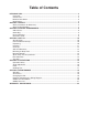
Table of Contents INTRODUCTION ............................................................................................................................... 2 Foreword .................................................................................................................................... 2 Contact Info ................................................................................................................................ 2 Machine Data Sheet.............................................
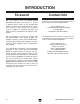
INTRODUCTION Foreword Contact Info We are proud to offer the Model G0489 Metalworking Sander. This machine is part of a growing Grizzly family of fine metalworking machinery. When used according to the guidelines set forth in this manual, you can expect years of trouble-free, enjoyable operation and proof of Grizzly’s commitment to customer satisfaction. If you have any comments regarding this manual, please write to us at the address below: We are pleased to provide this manual with the Model G0489.
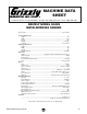
MACHINE DATA SHEET Customer Service #: (570) 546-9663 • To Order Call: (800) 523-4777 • Fax #: (800) 438-5901 GRIZZLY MODEL G0489 METALWORKING SANDER Design Type ..................................................................................................... Floor Model Product Dimensions: Height .......................................................................................................................48" Width ...............................................................................
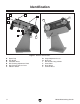
Identification C B I L C K A D E F G H J Figure 1. Machine Identification. A. B. C. D. E. F. -4- Spark Trap Eye Shield Tool/Work Rests Belt Tracking Adjustment Knob Belt Tension Release Lever ON/OFF Switch G. H. I. J. K. L.
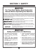
SECTION 1: SAFETY For Your Own Safety, Read Instruction Manual Before Operating this Machine The purpose of safety symbols is to attract your attention to possible hazardous conditions. This manual uses a series of symbols and signal words which are intended to convey the level of importance of the safety messages. The progression of symbols is described below. Remember that safety messages by themselves do not eliminate danger and are not a substitute for proper accident prevention measures.
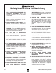
Safety Instructions for Machinery 7. ONLY ALLOW TRAINED AND PROPERLY SUPERVISED PERSONNEL TO OPERATE MACHINERY. Make sure operation instructions are safe and clearly understood. 8. KEEP CHILDREN AND VISITORS AWAY. Keep all children and visitors a safe distance from the work area. 9. MAKE WORKSHOP CHILD PROOF. Use padlocks, master switches, and remove start switch keys. 10. NEVER LEAVE WHEN MACHINE IS RUNNING.
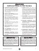
Additional Safety for Belt Sanders 1. RESPIRATOR AND SAFETY GLASSES. Always wear a respirator and safety glasses while operating the machine. Dust and chips are created when sanding. Some debris will be ejected, becoming hazards to the eyes and lungs. 2. PROTECT YOUR HEARING. Always wear approved hearing safety equipment when operating this belt sander. 3. DUST COLLECTION SYSTEM. Never operate the sander without an adequate dust collection system in place and running.
SECTION 2: CIRCUIT REQUIREMENTS 220 3-Phase Connection Type Recommended connection type (see Figures 2 & 3 for an example): 220V .............................Locking Shut-Off Switch Serious personal injury could occur if you connect your machine to the power source before you have completed the set up process. DO NOT connect the machine to the power source until instructed to do so. Amperage Draw The Model G0489 features a 220V motor that draws the following amps under maximum load: Motor Draw at 220V ..
Grounding Phase Converter In the event of an electrical short, grounding reduces the risk of electric shock. The grounding wire in the power cord must be properly connected to the grounding prong on the plug; likewise, the outlet must be properly installed and grounded. All electrical connections must be made in accordance with local codes and ordinances. When using a phase converter, the power from the manufactured power leg (sometimes called the wild wire) can fluctuate.
SECTION 3: SET UP Set Up Safety This machine presents serious injury hazards to untrained users. Read through this entire manual to become familiar with the controls and operations before starting the machine! Wear safety glasses during the entire set up process! The Model G0489 is a heavy machine. DO NOT over-exert yourself while unpacking or moving your machine—get assistance.
Inventory E. Base ........................................................... 1 After all the parts have been removed from the two boxes, you should have the following items: Box 1: (Figures 4 & 5) Qty A. Metalworking Sander.................................. 1 B. Spark Trap .................................................. 1 C. Eye Shield .................................................. 1 D. Rest ............................................................ 1 Hardware Bag (not shown)....................
Clean Up The unpainted surfaces are coated with a waxy oil to protect them from corrosion during shipment. Remove this protective coating with a solvent cleaner or citrus-based degreaser such as Grizzly’s G7895 Degreaser. To clean thoroughly, some parts may need to be removed. For optimum performance from your machine, make sure you clean all moving parts or sliding contact surfaces that are coated.
Mounting to Shop Floor Although not required, we recommend that you mount your new machine to the floor. Because this is an optional step and floor materials may vary, floor mounting hardware is not included. Generally, you can either bolt your machine to the floor or mount it on machine mounts. Both options are described below. Whichever option you choose, it is necessary to level your machine with a precision level. Figure 7. Typical lag shield anchor and lag bolt.
Mounting Sander This step may require three people to complete— two to lift and hold the sander in place, and one person to install the hardware. Components and Hardware Needed: Qty Sleeve ................................................................ 1 Hex Bolt M12-1.75 X 30 ..................................... 1 Hex Nut M12-1.75 .............................................. 1 Flat Washers 12mm .......................................... 2 Helpers ........................................................
Test Run Rest Lever Rest Once the assembly is complete, test run your machine to make sure it runs properly. If, during the test run, you cannot easily locate the source of an unusual noise or vibration, stop using the machine immediately. Square Nut Figure 13. Rest installation. If you cannot remedy a problem, contact our Tech Support at (570) 546-9663 for assistance.
SECTION 4: OPERATIONS Operation Safety Damage to your eyes, lungs, and ears could result from using this machine without proper protective gear. Always wear safety glasses, a respirator, and hearing protection when operating this machine. Angle Adjustment The sander can be angled up and down to meet your needs. Use the angle adjustment lever shown in Figure 14 to lock the sander in the angle you choose. Tighten securely so the sander will not move during operation.
Grinding Tips • When grinding against the contact wheel, make sure the belt guard is closed. • Hold work piece securely with both hands. Use the rests when possible to support the workpiece. • The workpiece will get hot as you continue to grind. Cool the workpiece frequently by quenching in water or another approved solution. • Change belts frequently for the best performance. • Do not force the work into the sander.
SECTION 5: MAINTENANCE Changing the Belt Always disconnect power to the machine before performing maintenance. Failure to do this may result in serious personal injury. Schedule For optimum performance from your machine, follow this maintenance and cleaning schedule and refer to any specific instructions given in this section. Daily Check: • Loose mounting bolts. • Worn or damaged belt. • Clean and chips and debris between platen and sanding belt. • Empty spark trap. • Sweep surrounding dust and chips.
Electrical Components & Wiring Diagram Switch �� Motor � �� � � � � � �� �� �� �� � ��������� ����� ��������������� � ���� �������������������� �� ����� ��������������� � ��� �������������������� � � �� � �� ����� ��������������� �� � � � � ������ G0489 Metalworking Sander -19-
G0489 Parts Breakdown ���� �� �� �� �� �� �� �� �� ���� �� �� �� �� �� �� �� �� �� �� �� �� �� �� �� �� �� ���� �� �� �� ���� �� �� �� �� �� �� �� � � � ���� � � �� �� �� �� � �� �� �� �� �� �� �� �� �� �� � � � �� �� �� �� �� �� �� �� �� �� �� �� �� �� �� �� �� �� �� �� �� �� 88 84 87 89 85 90 86 91 Safety labels warn about machine hazards and ways to prevent injury.
G0489 Parts List REF PART # DESCRIPTION REF PART # DESCRIPTION 1 P0489001 STAND 45 P0489045 STOP RING 2 ������ PW06M HEX BOLT M12-1.75 X 130 46 P6004 BEARING 6004 3 FLAT WASHER 12MM 47 P0489047 SHAFT 4 P0489004 PAPER SPACER 48 P0489048 SPACER 5 P0489005 PIVOT BASE 49 P0489049 MOTOR SUPPORT 6 PN02M HEX NUT M10-1.5 50 PN02M HEX NUT M10-1.5 7 PW04M FLAT WASHER 10MM 51 P0489051 THRUST WASHER 8 PW04M FLAT WASHER 10MM 52 P0489052 THREADED ROD M10-1.
WARRANTY AND RETURNS Grizzly Industrial, Inc. warrants every product it sells for a period of 1 year to the original purchaser from the date of purchase. This warranty does not apply to defects due directly or indirectly to misuse, abuse, negligence, accidents, repairs or alterations or lack of maintenance.
������������� ���������������������������������������������������������������������������������� � ������������������������������������������������������������������������������������ ����� ����������������������� ������������������������������� ���� ��������������������� ���������������������������� ������ ������������������������ ��������������������������� ���������������������������� ������������������������������� ��������������������������� �������������������������������������������������������������
���������������������� ����� ����� ���� ������������������������ ������������� �������������������������� ���������������������� ����������������������������������� ����������������������������������� ������������������������������������� �������������������������������������� ��������������������������������������
����������������������������������������������������������������������� ������������������������������������� ������������������������������������ ����������������� �������������������������������� ��������������������������������� ���� ��������������������� ������������������