MODEL G0492 12" X 36" COMBO LATHE/MILL OWNER'S MANUAL COPYRIGHT © AUGUST, 2006 BY GRIZZLY INDUSTRIAL, INC. WARNING: NO PORTION OF THIS MANUAL MAY BE REPRODUCED IN ANY SHAPE OR FORM WITHOUT THE WRITTEN APPROVAL OF GRIZZLY INDUSTRIAL, INC.
����������������������������������������������������������������������� �������������������������������������������������������������� ���������������������������������������������������������������������� �������������������������������������������������������������������� ������������������������ ������������������������������������������������������������������ �������������������������������������������������������������������� ����������������������������������������������������������������� ����������
Table of Contents INTRODUCTION ............................................................................................................................... 3 Foreword .................................................................................................................................... 3 Contact Info ................................................................................................................................ 3 Machine Data Sheet............................................
SECTION 7: SERVICE ................................................................................................................... 38 Cross Slide Backlash Adjustment ............................................................................................ 38 Gib Adjustments ....................................................................................................................... 38 Electrical Component and Connection Index .................................................................
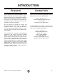
INTRODUCTION Foreword Contact Info We are proud to offer the Model G0492 12" X 36" Combo Lathe/Mill. This machine is part of a growing Grizzly family of fine metalworking machinery. When used according to the guidelines set forth in this manual, you can expect years of trouble-free, enjoyable operation and proof of Grizzly’s commitment to customer satisfaction.
MACHINE DATA SHEET Customer Service #: (570) 546-9663 • To Order Call: (800) 523-4777 • Fax #: (800) 438-5901 MODEL G0492 12" X 36" COMBO LATHE/MILL Product Dimensions: Machine Data Sheet Approximate Net Weight ...............................................................................................................................1200 lbs. Overall Dimensions ....................................................................................... 67-3/4" Wide x 26-3/4" Deep x 72" Tall Footprint ....
Lathe Information Mill/Drill Spindle Taper ...................................................................................................................... R8, 7/16"-20 TPI Spindle Bore .....................................................................................................................................................1-7/16" Lathe Spindle Taper...........................................................................................................................................
Identification I G D B A C K F E J L H M AA N Z Y X U T P S R Q V W G0492 12" X 36" Combo Lathe/Mill. A. B. C. D. E. F. G. H. I. J. K. L. M. N. -6- Lathe Emergency Stop Button Spindle Speed Lever Spindle Range Lever 3-Jaw Chuck Four-Way Tool Post Follow Rest Milling Speed Levers Compound Rest Elevation Handwheel Mill Power/Emergency Stop Button Milling Rack Handles Steady Rest Tailstock Lead Screw P. Chip Tray and Drip Pan Q. Longitudinal and Cross slide Lever R.
����������������� �������������������������������������� ������������������������������������ �������������������������������������������������������������������������������������������������� ������� ����� �� ������� ��� �������� ���� ������� ������ ������ ���� ��������� ��� ������� ���� ������ ��� ������������������������������������������������������������������������������������������� ����������������������������������������������������������������������������������������������� �����������������������
��������������������������������� ��� ����� ������ �������� ���� ����� ����� ����������� ���������� ��� �������� ����������� ����� ������ �������������������������������������������� ����������� ��� ��������������������������������� ����� ���� ��������� ���� ��������� �� ����� ���� ������������������������� ���� ������������������������������� ���������� ������� ���������� ���� ������� ������������������ ���� ������ ������ ����� �������� ��� �������������������������������������� ������� ������ ��� ����� ��
Additional Safety Instructions for Lathe/Mills 1. UNDERSTANDING THE MACHINE: Read and understand this manual before operating machine. 8. PREVENTING AN APRON-CHUCK CRASH: Always release automatic feeds after completing a job. 2. CLEANING MACHINE: To avoid entanglement and lacerations, do not clear chips by hand. Use a brush, and never clear chips while the lathe is turning. 9. 3. USING CORRECT TOOLING: Always select the right cutter for the job, and make sure cutters are sharp.
Glossary of Terms The following is a list of common definitions, terms and phrases used throughout this manual as they relate to this lathe/mill and metalworking in general. Become familiar with these terms for assembling, adjusting or operating this machine. Your safety is VERY important to us at Grizzly! Arbor: A machine shaft that supports a cutting tool. Backlash: Wear in a screw or gear mechanism that may result in slippage, vibration, and loss of tolerance.
SECTION 2: CIRCUIT REQUIREMENTS 220V Single-Phase Serious personal injury could occur if you connect the machine to the power source before you have completed the set up process. DO NOT connect the machine to the power source until instructed to do so. Grounding In the event of an electrical short, grounding reduces the risk of electric shock. The grounding wire in the power cord must be properly connected to the grounding prong on the plug; likewise, the outlet must be properly installed and grounded.
SECTION 3: SET UP Set Up Safety 2. Gather the following items: — Fork Lift or 2-ton hoist, and driver or operator. — 1 Ton lifting straps and hooks 3. Unbolt the crate sides and remove the top and sides. 4. Insert two lifting straps under the bedways and behind the feed rod and the lead screw as shown in Figure 2 and support the lathe with the lifting straps and lifting device. 5. Move the apron between the headstock and the mill column as shown in Figure 2 to balance the load.
Inventory A C B D After all the parts have been removed from the two boxes, you should have the following items: Installed Accessories (Figure 3) .................... Qty. A. 6" Three-Jaw Chuck ..................................... 1 B. 4-Way Tool Post and Compound Rest ........ 1 C. Follow Rest................................................... 1 D. Steady Rest .................................................. 1 Packaged Accessories (Figure 4) E. 8" Four-Jaw Universal Chuck .......................
Site Considerations Clean Up Floor Load The ways and other unpainted parts of your lathe/ mill are coated with a waxy grease that protects them from corrosion during shipment. Clean this grease off with a solvent cleaner or citrus-based degreaser. DO NOT use chlorine-based solvents such as brake parts cleaner, lacquer thinner, or acetone—if you happen to splash some onto a painted surface, you will ruin the finish. Your lathe/mill is a heavy load (1200 lbs.) distributed in a small footprint.
SECTION 4: LATHE OPERATIONS Operation Safety Damage to your eyes, lungs, and ears could result from using this machine without proper protective gear. Always wear safety glasses, a respirator, and hearing protection when operating this machine. The Power Supply When illuminated, the power lamp (Figure 6) indicates that power is being supplied to the lathe/ mill. Pressing the red emergency stop button will cut power for machine operations.
Test Run & Break-In NOTICE Make sure all power feed levers and dials 5. Move the half-nut lever upward to disengage the apron, and move the feed lever to the neutral or central position (see Figure 8). 6. Move the spindle rotation ON/OFF lever to its central position (OFF) as shown in Figure 8, and connect the lathe to power so the green lamp is lit.
Mounting the Chuck and the Faceplate 3. Use a 14mm wrench and loosen the three hex bolts that secure the chuck to the spindle Figure 10. The three-jaw scroll chuck has hardened steel jaws that self-center the workpiece within 0.002"0.003". An extra set of jaws is included for machining larger workpieces. The four-jaw chuck also has hardened steel jaws but are adjusted independently to hold an offcenter workpiece. Each jaw can be removed from the chuck body and reversed for special clamping applications.
Replacing the Jaws The three-jaw scroll chuck has removable hardened steel jaws (Figure 11). The outside of the jaws are used to hold the workpiece from the outer diameter. To remove a set of jaws: 1. DISCONNECT POWER TO THE LATHE/ MILL! 2. Place a piece of wood over the ways to protect them from potential damage. 3. Turn the chuck key counterclockwise and back the jaws out. 4. Clean the jaw mating surfaces and apply a film of white lithium grease to the mating surfaces. 5.
Using the Four-Jaw Chuck 5. Turn each jaw until it just makes contact with the workpiece. 6. In an opposing pattern, tighten each jaw in small increments. After you have adjusted the first jaw, continue tightening the opposing jaw. Check the dead center alignment frequently to make sure you have not wandered off your index point due to applying too much pressure to a single jaw. 7. After the workpiece is held in place, back the tailstock away and rotate the chuck by hand.
Using the Faceplate The faceplate can be used to turn non-cylindrical parts or for off-center turning by clamping the workpiece to the faceplate. To install the faceplate: Refer to the Mounting the Chuck and Faceplate procedures on Page 17 to mount the faceplate. To load a workpiece: 1. Support the workpiece. 2. Slide the tailstock to the workpiece. 3. Lock the tailstock and then turn the tailstock quill so the dead center makes contact with the center point of your workpiece. 4.
Using the Tailstock The tailstock (Figure 17) can be used to support workpieces with the use of a live or dead center. Using an MT#3 drill chuck and a drill bit, the lathe can drill or bore holes in the center of a part. The tailstock can also be offset for cutting shallow tapers. To use the tailstock: Drilling with the Tailstock To install the MT#3 drill chuck: 1. With the tailstock locked, unlock the quill lock lever. 2. Turn the quill feed handle clockwise to extend the quill about one inch. 3.
Cutting Shallow Tapers with Tailstock To setup the tailstock to cut tapers: Aligning Tailstock The tailstock is aligned at the factory with the headstock. We recommend that you take the time to ensure that the tailstock is aligned to your own desired tolerances. To align the tailstock: 1. Lock the tailstock in position. 2. Alternately loosen and tighten the left and right offset adjustment screws until the desired offset is indicated on the scale (see Figures 19 & 20). 3. Retighten the lock screw.
5. Place the live center in the tailstock. 6. Attach a lathe/mill dog to the bar stock and mount it between centers. 7. Turn approximately 0.010" off the diameter. 8. Measure the stock with a micrometer. —If the stock diameter is thinner at the tailstock end, the tailstock needs to be moved away from you half the distance of the amount of the taper (see Figure 23).
Using the Centers The dead center is used in the tailstock and lathe spindle to support workpieces. When used in the tailstock, make sure to keep the MT#3 dead center tip and workpiece lubricated to prevent tip galling. This lathe/mill is also supplied with an MT#5 dead center that fits into the lathe spindle taper. To install a dead or live center: 1. Feed the quill out about 1" and insert the MT#3 dead center (Figure 24). The mating tapers provide the locking action. Figure 24. Inserting dead center. 2.
Using the Steady Rest Using the Follow Rest The steady rest serves as a support for long shafts. The steady rest can be placed anywhere along the length of the ways. The follow rest in Figure 27 is mounted on the saddle and follows the movement of the tool. The follow rest requires only two fingers, as the cutting tool acts as the third. The follow rest is used on long, slender parts to prevent flexing of the workpiece from the pressure of the cutting tool. To use the steady rest: 1. 2.
Using the Compound Rest The compound rest is used to cut tapers on parts or to set the proper infeed angle when threading. It may also be used to cut specific lengths longitudinally, when set parallel to the spindle axis. To set the angular position: 1. Loosen the hex nuts, one on each side of the compound rest (see Figure 28). 2. Rotate the compound rest to the desired angular position using the scale. 3. Tighten the two hex nuts.
Using the Manual Feed Handwheels You can manually move the cutting tool around the lathe/mill with the three handwheels shown in Figure 30. Setting the Spindle RPM To determine and set the needed spindle RPM for cutting: 1. Compound Rest Handwheel S Cross Slide Handwheel Longitudinal Handwheel Figure 30. Carriage controls. Longitudinal Handwheel The longitudinal handwheel moves the carriage left or right along the bed.
2. Determine the average final diameter of the workpiece in inches, for the cut to be made. 3. Now use the following formula to determine the closest RPM for the cutting operation: (Cutting Speed x 4) Diameter of Cut Note: You may need to rotate the chuck by hand to get the gears to engage. RPM Lever = RPM 4. With the calculated RPM, decide on the closest cutting RPM to what you need. 5. Make sure the spindle is completely stopped before proceeding. 6.
Setting the Power Feed Rate The carriage has longitudinal and cross slide power feed capabilities. All directions reverse when spindle rotation is reversed. NOTICE Feed rate is based on spindle RPM. Pay close attention to the feed rate you have chosen and be ready to disengage the apron. Failure to do this may cause the carriage to crash into the chuck. To set and engage the power feed: 1. DISCONNECT THE LATHE/MILL FROM POWER! 2.
Setup for Threading 6. Use the leadscrew lever to select leadscrew direction (Figure 37). Your lathe is capable of cutting inch and metric threads. 7. Setup the cutting tool, compound rest, and cross slide to cut your threads; and loosen the apron lock (Figure 35). To setup for threading: 1. 2.
Change Gear Chart G0492 12" X 36" Combo Lathe/Mill -31-
SECTION 5: MILL OPERATIONS Test Run & Break-In NOTICE Failure to follow start up and spindle breakin procedures will cause rapid deterioration of spindle and other related parts, and never shift gears while lathe or mill is running. It is essential to closely follow the proper break-in procedures to ensure trouble free performance. Complete this process once you have familiarized yourself with all instructions in this manual. 5. Turn the spindle ON and run it a minimum of 10 minutes.
Positioning the Headstock The mill headstock head can be raised and lowered vertically, or rotated left or right up to 90º degrees to position the cutting tool next to the workpiece. To position the spindle head vertically: 1. Make sure the spindle is stopped and the work area is free from obstructions before proceeding. 2. Loosen both column lock levers so that the headstock can freely slide on the column (Figure 41). 3.
Installing Cutters To install a cutter in the spindle: 1. DISCONNECT THE LATHE/MILL FROM POWER! 2. Carefully clean the surface of the arbor and spindle taper. Ensure that they are free of debris and burrs. 3. Insert the arbor into the spindle, and rotate the arbor so the slot in the arbor lines up with the pin inside of the spindle. 4. Press the arbor up firmly to seat it with the spindle. 5. Drawbar Nut Figure 45. The drawbar. 6.
Setting the Spindle RPM Note: You will only be able to get an approximate RPM value with the variable speed knob. 4. NOTICE Never shift gears while lathe or mill is running; otherwise, the gear teeth will be chipped or broken. To determine and set the mill to the needed cutting RPM: 1. NOTICE Failure to follow RPM and Feed Rate Guidelines will shorten cutter life and give poor workpiece results and may threaten operator safety from ejected parts or broken tools.
SECTION 6: MAINTENANCE Basic Maintenance Regular periodic maintenance of your lathe/mill will ensure optimum performance. Make a habit of inspecting your machine each time you use it. Check for the following conditions and repair or replace when necessary: • • • • Loose mounting bolts and chuck. Worn switch or safety features. Worn or damaged cords and plugs. Any other condition that could hamper the safe operation of this machine. General Lubrication Headstock Oil Fill Plug Figure 49.
Belt Adjustment or Replacement For daily lubrication, use a manual oil gun with a general 10W machine oil to lubricate the following 15 ball oiler fittings. See Figure 51 for some typical locations.
SECTION 7: SERVICE Cross Slide Backlash Adjustment Backlash is the amount of play found in a lead screw. It can be found by turning the cross slide handwheel in one direction, and then turning the handwheel the other direction. When the cross slide begins to move, the backlash has been taken up. Note: Avoid the temptation to overtighten the cross slide backlash screw. Overtightening will cause excessive wear to the sliding block and lead screw.
Electrical Component and Connection Index (KM1) Main System Contactor See Figure 58 Figure 60 (KM2, KM3) Spindle Motor Direction Contactors Figure 61 Figure 68 (TC) Transformer Figure 67 Figure 59 Figure 62 Figure 63 Figure 57. G0492 Electrical panel.
Electrical Connections Figure 60. Contactor wiring (KM2 and KM3). Figure 58. Contactor wiring (KM1). Figure 61. Contactor wiring (KM2 and KM3). Figure 59. Junction block wiring. Figure 62. Junction block wiring. Figure 63. Junction block wiring.
Electrical Connections Figure 67. Transformer output connection. Figure 64. Motor connection. Figure 68. Transformer input connection. Figure 65. Start capacitor. Figure 66. Mill power switch. Figure 69. Lathe motor direction limit switches.
Electrical Connections Emergency Stop Switch Power Lamp Jog Button Figure 70. Lathe controls. Figure 71. Lathe control panel wiring.
Troubleshooting Review the troubleshooting and procedures in this section to fix your machine if a problem develops. If you need replacement parts or you are unsure of your repair skills, then feel free to call our Technical Support at (570) 546-9663. Motor & Electrical Symptom Possible Cause Possible Solution Motor will not start. 1. 2. 3. 4. 1. 2. 3. 4. Incorrect lathe operation. Main power panel switch is OFF. Emergency switch is pushed in. Circuit breaker or fuse has tripped. 5.
Troubleshooting Operation and Work Results Symptom Possible Cause Possible Solution Entire machine vibrates excessively upon startup and while running. 1. Workpiece is unbalanced. 1. Reinstall workpiece so it is as centered with the spindle bore as possible. 2. Inspect gears and replace if necessary. 3. Rebalance chuck or faceplate; contact a local machine shop for help. 4. Replace spindle bearings. 2. Worn or broken gear present. 3. Chuck or faceplate has become unbalanced. 4.
Troubleshooting Operation and Work Results (Continued) Symptom Possible Cause Loud, repetitious noise coming from machine at or near the motor. 1. Pulley setscrews or keys are missing or 1. Inspect keys and setscrews. Replace or tighten if necessary. loose. 2. Tighten fan or shim cover, or replace items. 2. Motor fan is hitting the cover. Motor is loud when cutting. Overheats or bogs down in the cut. 1. Excessive depth of cut or feed rate. 2. RPM or feed rate wrong for cutting operation. 1.
SECTION 8: ACCESSORIES H2689—R8 Quick Change Collet Set An affordable quick change collet system with ultra precision. These spring collets are hardened and ground to exacting tolerances and offer incredible holding power. This set inlcudes an R8 arbor and nut, spanner wrench, plastic carrying case and collets sized 1⁄ 8", 1⁄4", 3 ⁄ 8", 1⁄ 2", 5 ⁄ 8", 3 ⁄4", 7⁄ 8", and 1". What's more, the nut features a self-ejecting rim! A set like this will truly speed up any tool changing process.
SECTION 9: PARTS Electrical Box (0000 Series Parts) 6 7 1 2 4 3 8 11 9 10 0000 Series Parts List REF PART # DESCRIPTION REF PART # DESCRIPTION 1 P04920001 2 P04920002 3 P04920003 4 P04920004 CONTACTOR (LC1-D0910, B5, 24V, 50HZ) CONTACTOR (LC1-D1201, B5, 24V, 50HZ) CONTACTOR (LC1-D1201, B5, 24V, 50HZ) TRANSFORMER (JBK5-63), (INPUT 220V +/- 5%, OUTPUT 24V) 6 7 8 9 10 10-1 11 P04920006 P04920007 P04920008 P04920009 P04920010 P04920010-1 P04920011 FUSE 2A FUSE HOUSING TERMINAL BLOCK ST
-48- 1050 1052 1052 1053 105 4 1007 1004 1005 1006 1002 1003 1001 1005-1 1033 103 4 101 3 103 2 1026 1025 1014-2 1014-1 1014-3 1014-4 Change Gears 1055-1 to 1055-17 1058 1057 1056 1014 1015 1016 1017 1018 1019 1020 1021 1022 1023 1024 102 7 102 8 102 9 103 0 1031 1036 103 5 104 2 104 3 104 4 1037 104 5 104 6 1047 1048 103 8 1039 104 0 1041 1049 1008 1009 1010 1011 1012 Lathe Change Gear Housing Diagram (1000 Series Parts) G0492 12" X 36" Combo Lathe/Mill
1000 Series Parts List REF PART # DESCRIPTION REF PART # DESCRIPTION 1001 1002 1003 1004 1005 1005-1 1006 1007 1008 1009 1010 1011 1012 1013 1014 1014-1 1014-2 1014-3 1014-4 1015 1016 1017 1018 1019 1020 1021 PS38M PLW02M PN04M P04921004 P04921005 P04921005-1 PVA71 P04921007 PSS03M PB07M PLW04M PW01M P04921012 P04921013 P04921014 P04921014-1 P04921014-2 P04921014-3 P04921014-4 P04921015 P04921016 P04921017 PW04M PN02M PRP64M P04921021 1022 1023 1024 1025 1026 1027 1028 1029 1030 P04921022 PW06M PEC
-502703 2748 2747 2746 2745 2744 2749 2751 2750 2701 2702 2704 2743 2705 2714 2742 2741 2739 2740 2724 2725 2720 2734 2733 2732 2731 2730 2729 2728 2719 2726 2727 2718 2717 2716 2715 2737 2738 2721 2722 2723 2713 2736 2712 2735 2707 2711 2706 2710 2708 2709 Leadscrew Gearbox Diagram (2700 Series Parts) G0492 12" X 36" Combo Lathe/Mill
2700 Series Parts List REF PART # DESCRIPTION REF PART # DESCRIPTION 2701 2702 2703 2704 2705 2706 2707 2708 2709 2710 2711 2712 2713 2714 2715 2716 2717 2718 2719 2720 2721 2722 2723 2724 2725 2726 P04922701 PS05M P04922703 P04922704 P04922705 PK08M P04922707 P04922708 P04922709 P04922710 P04922711 PK127M P04922713 P04922714 P04922715 P04922716 P04922717 P04922718 P04922719 PS07M PR06M P04922722 PK126M P04922724 P8102 P04922726 COVER PLATE PHLP HD SCR M5-.8 X 8 BALL OILER 8MM SPECIAL SET SCREW M5-.
-523080 3081 3079 3075 3007 3077 3078 3072 3073 3074 3045 3052 3044 3043 3042 3041 3040 3034 3033 3035 3054 3053 3046 3070 3064 3065 3066 3067 3068 3069 3007 3058 3057 3056 3055 3039 3051 3007 3038 3049 3037 3048 3036 3047 3022 3024 3026 028 007 3020 3 3030 3 3021 3027 3023 3025 309 0 3091 309 2 3097 309 3 309 4 3098 3104 3007 3099 3083 3096 31 0 5 3007 31 0 7 308 4 3082 309 6-1 308 8 3110 3108 3007 308 5 31 0 9 310 6 308 9 308 7 3111 3102 3100 3101 3071 3032 3031 3017 3019 3005 3007 3
3000 Series Parts List REF PART # DESCRIPTION REF PART # DESCRIPTION 3001 3002 3003 3004 3005 3006 3007 3008 3009 3010 3011 3012 3013 3014 3015 3016 3017 3018 3019 3020 3021 3022 3023 3024 3025 3026 3027 3028 3030 3031 3032 3033 3034 3035 3036 3037 3038 3039 3040 3041 3042 3043 3044 3045 3046 3047 3048 3049 3051 3052 3053 3054 3055 P04923001 P04923002 PW08M PK08M P04923005 P04923006 PSB33M P04923008 P04923009 PR06M P04923011 P04923012 P04923013 P04923014 PSB13M P04923016 P04923017 P04923018 P04923019
Compound Rest and Tool Post Diagram (3500 Series Parts) ���� ���� ���� ���� ���� ���� ���� ���� ���� ���� ���� ���� ���� ���� ���� ���� ���� ���� ���� ���� ���� ���� ���� ���� ���� ���� ���� ���� ���� ���� ���� ���� ���� ���� ���� ���� ���� ���� ���� -54- G0492 12" X 36" Combo Lathe/Mill
3500 Series Parts List REF PART # DESCRIPTION REF PART # DESCRIPTION 3501 3502 3503 3504 3505 3506 3507 3508 3509 3510 3511 3512 3513 3514 3515 3516 3517 3518 3519 3520 P04923501 P04923502 P04923503 P04923504 P04923505 P04923506 P04923507 P04923508 P04923509 PSS64M PN01M PSS01M P04923513 P04923514 P04923515 PSB01M P04923517 P04923518 P04923519 P04923520 FEMALE KNOB 5/16-18 LEVER 5/16-20 TOOL POST BOLT M10-1.
-56- 4073 4072 4079 4078 4074 4070 4071 4072-1 4076 4077 4075 4064 4001 4062 4085 4084 4063 4069 4061 4065 4066 4067 4068 4083 4081 4080 4082 4059 4060 4058 4054 4055 4056 4057 4052 4053 4018 4020 4019 40274028 4030 4029 4031 4032 4033 4034 4036 4035 4037 4038 4021 4022 4023 4024 4025 4 404 039 4026 0 4041 4017 4011 4012 4013 4010 4014 4008 4015 4009 4016 4006 4007 4045 4044 4047 4049 4043 4048 4050 4046 4042 4051 4004 4002 4003 4005 Bed Diagram (4000 Series Parts) G04
4000 Series Parts List REF PART # DESCRIPTION REF PART # DESCRIPTION 4001 4002 4003 4004 4005 4006 4007 4008 4009 4010 4011 4012 4013 4014 4015 4016 4017 4018 4019 4020 4021 4022 4023 4024 4025 4026 4027 4028 4029 4030 4031 4032 4033 4034 4035 4036 4037 4038 4039 4040 4041 4042 4043 P04924001 P04924002 P04924003 PSB11M P04924005 P04924006 PS08M PSS12M PN01M PSB48M P04924011 P04924012 PSB07M PSB30M PB47M P04924016 PFH07M P04924018 PSS09M PN03M P04924021 P04924022 P04924023 P04924024 PK08M PK29M P8201
Steady Rest and Follow Rest Diagram (4500 Series Parts) ���� ���� ���� ���� ���� ���� ���� ���� ���� ���� ���� ���� ���� ���� ���� ���� ���� ���� ���� ���� ���� ���� ���� ���� ���� ���� ���� ���� ���� ���� ���� ���� ���� -58- G0492 12" X 36" Combo Lathe/Mill
4500 Series Parts List REF PART # DESCRIPTION REF PART # DESCRIPTION 4501 4502 4503 4504 4505 4506 4507 4508 4509 4510 4511 4512 4513 P04924501 P04924502 P04924503 P04924504 P04924505 PN01M P04924507 P04924508 P04924509 P04924510 PW01M P04924512 P04924513 PINNED KNOB ADJUSTMENT STUD TAPERED PIN BRASS-TIPPED FINGER SPECIAL SET SCREW M6-1 HEX NUT M6-1 THUMB KNOB M6-1.0 X 20 CLEVIS PIN 8 X 32MM COTTER PIN 3 X 25MM STEADY REST HEAD FLAT WASHER 8MM STEADY REST BASE FEMALE KNOB M8-1.
Tailstock Diagram (5700 Series Parts) 5728 5727 5726 5725 5724 5723 5715 5716 5717 5720 5718 5729 5722 5721 5719 5714 5730 5713 5712 5739 5731 5711 5710 5732 5740 5733 5741 5709 5734 5708 5707 5706 5735 5705 5704 5703 5736 5702 5701 5737 5738 -60- G0492 12" X 36" Combo Lathe/Mill
5700 Series Parts List REF PART # DESCRIPTION REF PART # DESCRIPTION 5701 5702 5703 5704 5705 5706 5707 5708 5709 5710 5711 5712 5713 5714 5715 5716 5717 5718 5719 5720 5721 P04925701 P04925702 P04925703 P04925704 PR03M P04925706 PSB12M P04925708 P04925709 P04925710 P04925711 P04925712 P04925713 P04925714 P04925715 P04925716 P04925717 P04925718 P04925719 PK125M P04925721 SPECIAL SET SCREW M5-.8 X 8 COMPRESSION SPRING BALL OILER STEEL BALL 8MM EXT RETAINING RING 12MM DOWEL NUT CAP SCREW M8-1.
-62- 6078 6074 6073 6072 6068 6071 6059 6064 6067 6066 6065 6060 6069 6079 6063 6058 6057 6052 6051 6050 6033 6032 6061 6062 6054 6055 6053 6022 6021 6020 6019 6023 6056 6017 6018 6016 6015 6014 6013 6070 6012 6011 6010 6008 6009 6007 6075 6006 6076 6077 6005 6004 6003 6001 6002 6024 6036 6037 6043 6044 6045 6042 6046 6041 6047 6048 6049 6035 6034 6030 6031 6028 6029 6027 6026 6025 6040 6039 6038 Apron Diagram (6000 Series Parts) G0492 12" X 36" Combo
6000 Series Parts List REF PART # DESCRIPTION REF PART # DESCRIPTION 6001 6002 6003 6004 6005 6006 6007 6008 6009 6010 6011 6012 6013 6014 6015 6016 6017 6018 6019 6020 6021 6022 6023 6024 6025 6026 6027 6028 6029 6030 6031 6032 6033 6034 6035 6036 6037 6038 6039 6040 PK81M P04926002 P04926003 PSS04M P04926005 P04926006 P04926007 P04926008 P04926009 P04926010 PR09M P04926012 P04926013 P04926014 P04926015 P04926016 PSB79M P04926018 PR03M PK29M P04926021 P04926022 P04926023 P04926024 P04926025 P0492602
-647520 7519 7501 7517 7588 7518 7509 7510 7527 7516 7515 7514 7526 7525 7513 7502 7503 7504 7505 7506 7507 7508 7521 7511 7522 7523 7512 7524 7542 7541 7540 7539 7538 7534 7535 7533 7532 7589 7531 7530 7529 7528 7546 7537 7536 7543-4 7543-5 7543 7543-1 7584 7583 7582 7581 7585 7547 7544 7545 7543-2 7543-3 7580 7579 7586 7550 7549 7548 7587 7578 7559 7558 7557 7556 7555 7554 7552 7553 7551 7577 7576 7575 7574 7573 7571 7572 7570 7569 7568 75
7500 Series Parts List REF PART # DESCRIPTION REF PART # DESCRIPTION 7501 7502 7503 7504 7505 7506 7507 7508 7509 7510 7511 7512 7513 7514 7515 7516 7517 7518 7519 7520 7521 7522 7523 7524 7525 7526 7527 7528 7529 7530 7531 7532 7533 7534 7535 7536 7537 7538 7539 7540 7541 7542 7543 7543-1 7543-2 7543-3 7543-4 PR12M P04927502 P04927503 P04927504 P04927505 P04927506 PR12M P04927508 P04927509 P04927510 PFH31M P04927512 P04927513 P04927514 P04927515 P04927516 P04927517 P04927518 P04927519 P04927520 P049
Mill Column Diagram (8000 Series Parts) 8014 8013 8012 8017 8015 8018 8016 8011 8010 8009 8008 8030 8019 8029 8028 8027 8026 8007 8006 8020 8021 8025 8022 8005 8023 8024 8004 8003 8002 8001 -66- G0492 12" X 36" Combo Lathe/Mill
8000 Series Parts List REF PART # DESCRIPTION REF PART # DESCRIPTION 8001 8002 8003 8004 8005 8006 8007 8008 8009 8010 8011 8012 8013 8014 8015 P04928001 P04928002 PLW05M PSB92M PLW05M PSB119M P04928007 P04928008 PSB02M P8106 P04928011 P04928012 P04928013 PN41M P04928015 PEDESTAL TAPER PIN LOCK WASHER 12MM CAP SCREW M12-1.75 X 40 LOCK WASHER 12MM CAP SCREW M12-1.75 X 55 COLUMN COLUMN FLANGE CAP SCREW M6-1 X 20 BALL BEARING 8106 COLUMN BRACKET TANG WASHER SPANNER NUT M30-1.5 ACORN NUT M10-1.
Accessories and Labels Diagram (9000 Series Parts) 9004 9016 9013 9020 9009 9017 9014 9005 9048 9006 9015 9008 9010 9033 9022 9001 9012 9007 9047 9046 9045 9023 9044 9021 9011 9039 9040 9041 9038 9024 9037 9034 9032 9025 9026 9030 9028 9043 9035 -68- 9027 9031 9029 G0492 12" X 36" Combo Lathe/Mill
9000 Series Parts List REF PART # DESCRIPTION REF PART # DESCRIPTION 9001 9004 9005 9006 9007 9008 P04929001 P04929004 P04929005 P04929006 P04929007 P04929008 9008-1 9008-2 9008-3 9008-4 9009 9009-1 9009-2 9009-3 9009-4 9010 9011 9012 9013 9014 9015 9016 9017 9020 9021 P04929008-1 P04929008-2 P04929008-3 P04929008-4 P04929009 PAW02M PAW04M PAW06M PAW08M P04929010 P04929011 P04929012 P04929013 P04929014 P04929015 P04929016 P04929017 P04929020 P04929021 6" THREE-JAW CHUCK 8" FOUR-JAW UNIVERSAL CHUCK
WARRANTY AND RETURNS Grizzly Industrial, Inc. warrants every product it sells for a period of 1 year to the original purchaser from the date of purchase. This warranty does not apply to defects due directly or indirectly to misuse, abuse, negligence, accidents, repairs or alterations or lack of maintenance.
������������� ���������������������������������������������������������������������������������� � ������������������������������������������������������������������������������������ ����� ����������������������� ������������������������������� ���� ��������������������� ���������������������������� ������ ������������������������ ��������������������������� ���������������������������� ������������������������������� ��������������������������� �������������������������������������������������������������
���������������������� ����� ����� ���� ������������������������ ������������� �������������������������� ���������������������� ����������������������������������� ����������������������������������� ������������������������������������� �������������������������������������� ��������������������������������������
����������������������������������������������������������������������� ������������������������������������� ������������������������������������ ����������������� �������������������������������� ��������������������������������� ���� ��������������������� ������������������