MODEL G0513X2B 17" BANDSAW w/MOTOR BRAKE Manual Insert The Model G0513X2B is the same as the Model G0513X, except it has a cast iron trunnion, key switch, and a magnetic brake motor. Besides the data sheet, circuit requirements, certain setup and operation procedures, the wiring diagram, and parts in this insert, the content in the Model G0513X owner's manual is the same for both machines. On the following pages, the header indicates which page it replaces in the Model G0513X manual, if applicable.
0$&+,1( '$7$ 6+((7 Customer Service #: (570) 546-9663 · To Order Call: (800) 523-4777 · Fax #: (800) 438-5901 02'(/ * ; % +3 (;75(0( 6(5,(6Þ %$1'6$: : &$67 ,521 75811,21 %5$.( Product Dimensions: Weight.............................................................................................................................................................. 352 lbs. Width (side-to-side) x Depth (front-to-back) x Height...........................................................................
Blade Information Standard Blade Length...................................................................................................................... 131-1/2 in. Blade Width Range................................................................................................................................ 1/8-1 in. Upper Blade Guides........................................................................................................................ Ball Bearing Lower Blade Guides................
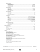
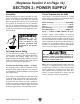
(Replaces Section 1 on Page 11) SECTION 1: SAFETY For Your Own Safety, Read Instruction Manual Before Operating this Machine The purpose of safety symbols is to attract your attention to possible hazardous conditions. This manual uses a series of symbols and signal words intended to convey the level of importance of the safety messages. The progression of symbols is described below.
DISCONNECTING POWER SUPPLY. 6alVnh Y^h" XdccZXi bVX]^cZ [gdb edlZg hjeean WZ[dgZ hZg" k^X^c\! VY_jhi^c\! dg X]Vc\^c\ Xjii^c\ iddah W^ih! WaVYZh! XjiiZgh! ZiX# # BV`Z hjgZ hl^iX] ^h ^c D;; edh^i^dc WZ[dgZ gZXdccZXi^c\ id Vkd^Y Vc jcZmeZXi" ZY dg jc^ciZci^dcVa hiVgi# APPROVED OPERATION.
Additional Safety for Bandsaws BLADE CONDITION. Do not operate with dull, cracked or badly worn blade. Dull blades require more effort to perform the cut and increase the risk of kickback. Inspect blades for cracks and missing teeth before each use. HAND PLACEMENT. Never position fingers or hands in line with the blade. If the workpiece or your hands slip, serious personal injury could occur. WORKPIECE MATERIAL.
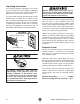
(Replaces Section 2 on Page 14) SECTION 2: POWER SUPPLY Availability Circuit Requirements for 220V 7Z[dgZ ^chiVaa^c\ i]Z bVX]^cZ! Xdch^YZg i]Z VkV^a" VW^a^in VcY egdm^b^in d[ i]Z gZfj^gZY edlZg hjeean X^gXj^i# >[ Vc Zm^hi^c\ X^gXj^i YdZh cdi bZZi i]Z gZfj^gZbZcih [dg i]^h bVX]^cZ! V cZl X^gXj^i bjhi WZ ^chiVaaZY# Id b^c^b^oZ i]Z g^h` d[ ZaZXigdXj" i^dc! [^gZ! dg Zfj^ebZci YVbV\Z! ^chiVaaVi^dc ldg` VcY ZaZXig^XVa l^g^c\ bjhi WZ YdcZ Wn V fjVa^[^ZY ZaZXig^X^Vc ^c VXXdgYVcXZ l^i] Vaa Vee
Grounding Instructions I]^h bVX]^cZ BJHI WZ \gdjcYZY# >c i]Z ZkZci d[ XZgiV^c bVa[jcXi^dch dg WgZV`Ydlch! \gdjcY^c\ gZYjXZh i]Z g^h` d[ ZaZXig^X h]dX` Wn egdk^Y^c\ V eVi] d[ aZVhi gZh^hiVcXZ [dg ZaZXig^X XjggZci# I]Z edlZg XdgY VcY eaj\ heZX^[^ZY jcYZg ¸8^gXj^i GZfj^gZbZcih [dg ''%K¹ dc i]Z egZk^djh eV\Z ]Vh Vc Zfj^ebZci"\gdjcY^c\ l^gZ VcY V \gdjcY" ^c\ egdc\# I]Z eaj\ bjhi dcan WZ ^chZgiZY ^cid V bViX]^c\ gZXZeiVXaZ djiaZi i]Vi ^h egdeZgan ^chiVaaZY VcY \gdjcYZ
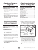
(Replaces Inventory on Page 17) I]Z [daadl^c\ ^h V YZhXg^ei^dc d[ i]Z bV^c Xdbed" cZcih h]^eeZY l^i] ndjg bVX]^cZ# AVn i]Z Xdbed" cZcih dji id ^ckZcidgn i]Zb# >[ Vcn cdc"egdeg^ZiVgn eVgih VgZ b^hh^c\ Z#\# V cji dg V lVh]Zg ! lZ l^aa \aVYan gZeaVXZ i]Zb0 dg [dg i]Z hV`Z d[ ZmeZY^ZcXn! gZeaVXZbZcih XVc WZ dWiV^cZY Vi ndjg adXVa ]VgYlVgZ hidgZ# Crate Contents (Figure 2): Qty A. Bandsaw (not shown).................................. 1 B. Table w/Table Insert...................................
(Replaces Table on Page 21) (Replaces Installing Fence on Page 25) Components and Hardware Needed: Qty Hex Bolts M8-1.25 x 25 ..................................... 4 Components and Hardware Needed: Qty Fence Assembly................................................. 1 Front Rail ........................................................... 1 Rail Plates.......................................................... 3 Cap Screws M6-1 x 20....................................... 3 Flat Washers 6mm..................
3. Thread the fence handle into the fence, then tighten the hex nut against the fence pivot block (see Figure 4). Power Connection 6[iZg ndj ]VkZ XdbeaZiZY Vaa egZk^djh hZije ^chigjXi^dch VcY X^gXj^i gZfj^gZbZcih! i]Z bVX]^cZ ^h gZVYn id WZ XdccZXiZY id i]Z edlZg hjeean# Pivot Block Id Vkd^Y jcZmeZXiZY hiVgijeh dg egdeZgin YVb" V\Z! jhZ i]Z [daadl^c\ hiZeh l]ZcZkZg XdccZXi^c\ dg Y^hXdccZXi^c\ i]Z bVX]^cZ# Fence Handle Hex Nut Figure 4. Fence handle components. 4.
(Replaces Test Run on Page 21) To test run the machine: 1. Follow Steps 1-5 on G0513X Manual Page 26. 2. Verify that the machine is operating correctly by turning the switch disabling key (Figure 8) to "1" and turning the machine ON. —When operating correctly, the machine runs smoothly with little or no vibration or rubbing noises. — Investigate and correct strange or unusual noises or vibrations before operating the machine further.
(Replaces Aligning Fence on Page 31) To ensure cutting accuracy when the fence is first installed, the fence should be aligned with the miter slot. NOTICE Adjusting the fence parallel to the miter slot does not guarantee straight cuts. The miter slot may need to be adjusted parallel to the side of the blade. Refer to the "Aligning Table" instructions on G0513X Manual Page 30. To align the fence parallel with the miter slot: 1. DISCONNECT BANDSAW FROM POWER! 2.
Pointer Calibration 3. Loosen the pointer adjustment nut (Figure 12) and set the pointer in line with "0" and the measurement scale on the table. Your new bandsaw is equipped with a fence measurement system that includes a fence pointer, which must be calibrated when the bandsaw is first set up. Pointer Nut Pointer To calibrate the pointer: 1. If the fence is mounted on the right-hand side of the blade, remove it and re-install it on the left-hand side of the blade. 2.
(Replaces Lubrication on Page 45) To lubricate the blade guide rack and pinion: To lubricate the tension adjustment assembly: 1. DISCONNECT BANDSAW FROM POWER! 2. Open the top wheel cover and look through the top of the wheel. 3. Wipe off any existing grease and sawdust buildup on the blade tension adjustment assembly and tension lever cam. 4. Apply a thin coat of grease to the tension adjustment assembly and tension lever cam (see Figure 14). 1. DISCONNECT BANDSAW FROM POWER! 2.
Magnetic Brake Adjustment on The space between the magnetic motor brake and brake shoe is preset by the factory at 0.2mm. However, you should adjust this space every two to three years, or when it takes over five seconds for the brake to stop the motor. Tools Needed Phillips Head Screwdriver................................... 1 US Dollar Bills.................................................... 2 Hex Wrench 3mm............................................... 1 Hex Wrench 4mm................................
SECTION 8: WIRING I]ZhZ eV\Zh VgZ XjggZci Vi i]Z i^bZ d[ eg^ci^c\# =dlZkZg! ^c i]Z he^g^i d[ ^begdkZbZci! lZ bVn bV`Z X]Vc\" Zh id i]Z ZaZXig^XVa hnhiZbh d[ [jijgZ bVX]^cZh# 8dbeVgZ i]Z bVcj[VXijgZ YViZ d[ ndjg bVX]^cZ id i]Z dcZ hiViZY ^c i]^h bVcjVa! VcY hijYn i]^h hZXi^dc XVgZ[jaan# >[ i]ZgZ VgZ Y^[[ZgZcXZh WZilZZc ndjg bVX]^cZ VcY l]Vi ^h h]dlc ^c i]^h hZXi^dc! XVaa IZX]c^XVa Hjeedgi Vi *,% *)+".
G0513X2B Electrical Components Figure 17. Control panel wiring. Figure 19. Magnetic switch. Figure 18. Motor wiring. -18- READ ELECTRICAL SAFETY ON PAGE 17! Model G0513X2B (Mfg.
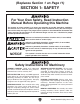
G0513X2B Wiring Diagram 220V, 1-Ph DC 7DM : =di A' =di A& G H 220 VAC 6-15 PLUG (as recommended)
-20- &,( &,& &,' &,"' '& &,"& &, &,* &,% '' &,) '( )- ** &,, &.", &."- &."- &."* '' &,+ ') '& &,"* &,") &,"' &-"* ') &,"( &+ &* &) &( &."+K' &. &-"' &-"& &."( &."' &- )' &.". &.") (% )( '* '. '- (- )% (, )& &."& - )+ )* )) (& (+ *& ( && &-"' &-"( &-"( &-") &' ), &% (' (( () (* ' , ). +& *% * +& -'"&% -'"&& -'"( -'". *. +. -'"&( &&& +% +' -, +& &&& +% )*% +, ++ +( (.
Main Parts List REF PART # DESCRIPTION REF PART # DESCRIPTION 2 3 4 5 7 8 10 11 12 13 14 15 16 17 17-1 17-2 17-3 17-4 17-5 18 18-1 18-2 18-3 18-4 18-5 19 19-1 19-2 19-3 19-4 19-5 19-6V2 19-7 19-8 19-9 21 22 23 24 25 28 29 30 31 32 33 34 35 36 37 38 39 40 41 42 43 44 45 46 PSS01M P0513X003 P0513004 P0513005 P0513X007 PW03M PN01M P0513011 P0513012 P0513013 PRP91M P0513015 P0513016 P0513X2B017 P0513017 P6204LLU PR25M P0513X2B017-4 T23071 P0513X2B018 P0513017 P6204LLU PR25M P0513X2B018-4 T23071 P0513X2B0
Main Parts List REF PART # DESCRIPTION REF PART # DESCRIPTION 170 171 172 173 FLANGE SCREW M5-.8 X 50 PHLP HD SCR M4-.7 X 10 EXT TOOTH WASHER 5MM CONNECTING CORD 174 175 176 177 TERMINAL BOX WIRE NUT P3 FLANGE SCREW M5-.8 X 10 STRAIN RELIEF 5/16" -22- PFS09M PS38M PTLW02M P0513X2B173 P0513X2B174 P0513X2B175 PFS07M P0513X2B177 Model G0513X2B (Mfg.
Fence-Guides Breakdown &*, &*,"&,K' &*,"&+ &*,"& &*,"&&*,"&( &*,"(K' &'+ &*,"&+ &*,"' &*,"&*,") &*'". &*'"- &*'"*K' &*'") &*,"&& &*,"&' &*,"&% &*,"+ &*,", &*,"* &*'"&) &*'"&( &*,"&)K' &*,"&* &*'"&* &*' &', &*'", &*'"& &*'"&& &*'"&% &*,". &*,"&( &*'"+ &*'"&'K' &+&"& &*+ &+& &*+") &*+"' &*+"& &+, &+) &+% &*. &+*K' &+. &,- &(& &*) &*&*( &+( &+- &(' &'- &+' &*+"( &*'"' &*'"( &*- &)* &)*"&& &)*"&&)*"&% &)*"&' &)*"&. &)*"&.
Fence-Guides Parts List REF PART # DESCRIPTION REF PART # DESCRIPTION 126 127 128 131 132 136 137 138 140 141 142 145 145-1 145-2 145-3 145-4 145-5 145-6 145-7 145-8 145-9 145-10 145-11 145-12 145-13 145-14 145-15 145-16 145-17 145-18 145-19 146 147 150 150-1 150-2 150-3 150-4 150-5 150-6 150-7 150-8 150-9 150-10 150-11 151 151-4 151-5 151-6 151-7 151-8 151-9 151-10 152 P0513X2B126 P0513X127 P0513X128 PBHS22M PLW04M PCAP50M PW02M P0513X138 P0513X140 P0513X141 P0513X142 P0513X2B145 PSS07M PCAP01M PS38
Trunnion Breakdown &**"&**", &**"& &**". &**"&+ &**"& &**"' &** &**"&% &**"( &**"&& &**") &**"(& &**"* &**"+ &**"'( &**"&' &**"& &**"&( &**"&) &**"&* &**"( &**"&, &**"') &**"(( &**"(% &**"'. &**"&- &**"& &**"&. &**"'%K' &**"' &**"(' &**"'& &**"'- &**"'' &**"', &**"'+ &(.K' &%( &%) &**"'* &%) &%( .
Labels Breakdown '%& '&+K' '%* '&) '%' '%( '&* '%) '%+ '%- '%, '%.
Accessories Some aftermarket accessories can be installed on this machine that could cause it to function improperly, increasing the risk of serious personal injury. To minimize this risk, only install accessories recommended for this machine by Grizzly. T20501—Face Shield Crown Protector 4" T20502—Face Shield Crown Protector 7" T20503—Face Shield Window T20452—"Kirova" Anti-Reflective S. Glasses T20451—"Kirova" Clear Safety Glasses H0736—Shop Fox® Safety Glasses H7194—Bifocal Safety Glasses 1.
Buy Direct and Save with Grizzly ® – Trusted, Proven and a Great Value! ~Since 1983~ Visit Our Website Today For Current Specials! ORDER 24 HOURS A DAY! 1-800-523-4777