8" WIDE BELT SANDER MODEL G0527 INSTRUCTION MANUAL COPYRIGHT © JUNE 2003 BY GRIZZLY INDUSTRIAL, INC. WARNING: NO PORTION OF THIS MANUAL MAY BE REPRODUCED IN ANY SHAPE OR FORM WITHOUT THE WRITTEN APPROVAL OF GRIZZLY INDUSTRIAL, INC.
WARNING Some dust created by power sanding, sawing, grinding, drilling, and other construction activities contains chemicals known to the State of California to cause cancer, birth defects or other reproductive harm. Some examples of these chemicals are: • Lead from lead-based paints. • Crystalline silica from bricks, cement, and other masonry products. • Arsenic and chromium from chemically treated lumber. Your risk from these exposures varies, depending on how often you do this type of work.
Table Of Contents SECTION 1: SAFETY........................................................................................................................2 Safety Instructions For Power Tools ..........................................................................................2 Additional Safety For Wide Belt Sanders....................................................................................4 SECTION 2: INTRODUCTION ..............................................................................
SECTION 1: SAFETY For Your Own Safety Read Instruction Manual Before Operating This Equipment The purpose of safety symbols is to attract your attention to possible hazardous conditions. This manual uses a series of symbols and signal words which are intended to convey the level of importance of the safety messages. The progression of symbols is described below. Remember that safety messages by themselves do not eliminate danger and are not a substitute for proper accident prevention measures.
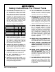
Safety Instructions For Power Tools 9. USE PROPER EXTENSION CORD. Make sure your extension cord is in good condition. Conductor size should be in accordance with the chart below. The amperage rating should be listed on the motor or tool nameplate. An undersized cord will cause a drop in line voltage resulting in loss of power and overheating. Your extension cord must also contain a ground wire and plug pin. Always repair or replace extension cords if they become damaged.
Additional Safety For Wide Belt Sanders 1. INFEED/OUTFEED AREA: DO NOT stand in-line with the infeed or outfeed areas when feeding the workpiece. 2. WORKPIECE FEEDING: DO NOT jam the workpiece into the machine and never feed more than one workpiece at a time. 3. CLOTHING: DO NOT wear loose clothing while operating this machine. Roll up or button sleeves at the cuff. 4. NARROW WORKPIECES: DO NOT sand workpieces narrower than 1⁄8''. 5. THIN WORKPIECES: DO NOT sand workpieces thinner than 1⁄8''. 6.
SECTION 2: INTRODUCTION Commentary Lack of familiarity with this manual could cause serious personal injury. Become familiar with the contents of this manual, including all the safety warnings. We are proud to offer the Model G0527 18" Wide Belt Sander. This machine is part of a growing Grizzly family of fine woodworking machinery.
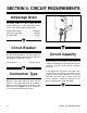
SECTION 3: CIRCUIT REQUIREMENTS Amperage Draw The Model G0527 has three motors that are wired to operate on a 220V single-phase power source. They will draw the following loads: Sanding Drum Motor ............................30 Amps Conveyor Feed Motor ..........................3.8 Amps Elevation Motor ......................................3 Amps Figure 1. Locking shut-off lever.
Minimum Cord Size Extension Cords For 220V single-phase operation, use the following power cord: Because of the high amperage draw from this machine, we do not recommend the use of extension cords. Instead, position your equipment near installed wiring to eliminate the need for extension cords. Cord ..............................................2 Pole, 3 Wire Gauge ................................................................
SECTION 4: MACHINE FEATURES External Features F E G A D B C Figure 2. Front view. A. B. C. D. E. F. G.
Control Panel R Q 1 2 3 4 5 6 7 8 9 0 P H O I N J M K L Figure 3. Control panel. H. I. J. K. L. M. N. O. P. Q. R.
Access Doors A B Figure 4. Inside the left access door. A. Belt Tension Switch B.
C D E H F G Figure 5. Inside the right access door. C. D. E. F. G. H.
SECTION 5: SET UP G0527 Inventory The Model G0527 is a heavy machine weighing in at 1870 lbs. Personal injury can occur if the machine is moved without additional assistance. Use lifting devices such as a fork lift when moving or lifting the machine. The Model G0527 was carefully packed when it left our warehouse. If you discover the machine is damaged after you have signed for delivery, immediately call our Service Department at (570) 546-9663.
Wing Nut ⁄ '' 58 10 # ⁄ '' 7 16 21⁄2'' 23⁄4'' 3 WASH WASH S WA H ASH DIA ER 8mm ASH W ASHE 6mm DI ER ASH R DIA ⁄ '' 14 D ER I ASH 21⁄4'' ⁄ '' 5 16 ET AM LINES ARE 1⁄16'' INCH APART LINES ARE 1MM APART 2 10mm R DIA ET AM 13⁄4'' 4mm MET G0527 18" Wide Belt Sander 11⁄2'' D ER IA TE ME R 16mm ⁄ '' ⁄ '' ⁄ '' ⁄ '' ⁄ '' 1'' 11⁄4'' 5 16 7 16 9 16 34 78 MET 12mm '' '' '' '' ⁄ '' 38 METE 10mm ⁄ ⁄ ⁄ ⁄ 14 38 12 58 DI ER ETER M 8mm 5mm 10mm 15mm 20mm 25mm 30mm 35mm 4
Clean Up Site Considerations The unpainted surfaces are coated with a waxy oil to protect them from corrosion during shipment. Remove this protective coating with a solvent cleaner or citrus-based degreaser such as Grizzly’s G7895 Degreaser. To clean thoroughly, some parts may need to be removed. For optimum performance from your machine, make sure you clean all moving parts or sliding contact surfaces that are coated.
Beginning Assembly Floor Mounting This section will cover the basic assembly and adjustment instructions needed to begin operation. Complete the assembly in the order provided in this manual and then read the remaining portion of the manual before attempting any type of operation. To mount the sander to the floor: Your safety is important! Please follow the warnings below during this entire section: Mount the sander to wooden floors with 1⁄2" lag bolts and washers.
Air Line Hook-Up To hook up the air line: 1. Connect the hose from your air compressor to the air inlet (Figure 7) on the regulator. 2. Make sure the red handle on the regulator is in the open position (parallel with the air inlet). Dust Collection An efficient and clean dust collection system is essential to the proper function of the sander. Ensuring a healthy work environment is also dependent upon cleaning and maintaining your dust collection system. To hook up the dust collection system: 1. 3.
Sanding Belt 4. Remove the spacer block (Figure 10). 5. Install the sanding belt by starting first on the upper roller and then the lower roller. Note— The sanding belt must be centered between the limit switches. If either edge of the sanding belt is touching either limit switch, turn the belt tension switch off and adjust the belt until it is properly centered as shown in Figure 11. To install the sanding belt: 1. Disconnect the sander from the power source! 2.
Pressure Rollers The pressure rollers have been set at the factory, but for safety, you should verify that they are set below the level of the sanding roller. Serious personal injury could result if the machine is connected to the power source during assembly or adjustment.
Starting the machine: 1. Wear safety glasses at all times when running the machine! 2. Connect the machine to the power source. 3. Press the TABLE UP and TABLE DOWN keys. The table should go up and down smoothly. 4. Press the FEED BELT START and FEED BELT STOP buttons. The feed belt should start, run and stop smoothly. 5. Press the SANDING BELT START and SANDING BELT STOP buttons. The sanding belt should start, run and stop smoothly.
SECTION 6: OPERATIONS Before Sanding Your safety is important! Please follow the warnings below during this entire section: Choosing Sandpaper NOTICE #100 and #150 grit sanding belts are included with the Model G0527. To avoid serious personal injury, read and become familiar with the entire instruction manual before using the Model G0527. Damage to your eyes, lungs, and ears could result from failure to wear safety glasses, a dust mask, and hearing protection while sanding with this machine.
Table Movement Adjusting Feed Rate The table height can be adjusted either manually or by power assist. The feed belt motor and gear assembly (Figure 13) controls the speed of the feed belt. The Model G0527 features feed belt speeds of 16.4, 23, and 32.8 FPM. Manual Adjustment—Manual adjustments are made by turning the handwheel located under the front of the infeed table. The thickness measurement is displayed on the digital readout.
Amperage Meter Sanding Workpiece The amperage meter is located above the control panel as shown in Figure 14. Use the meter to monitor the amperage load on the machine while performing sanding operations. Typically, no more than 0.5mm (approx. 1⁄64") of material is removed during each pass. Attempts to remove too much material can cause jamming, wood burning, rapid paper wear or tearing, poor finish and belt slippage. The following is the correct sanding operating procedure: 1.
SECTION 7: MAINTENANCE General Schedule Your safety is important! Please follow the warnings below during this entire section: The following items should be checked each time the sander is used: ON OFF Disconnect power to the machine when performing maintenance, assembly or adjustments. Failure to do this may result in serious personal injury. Loose hair and clothing could get caught in machinery causing serious personal injury.
Servicing Brakes 3. Pull the mounting pins out of the caliper bracket and remove the air line from the caliper. The caliper should now be able to be removed as in Figure 15. Eventually the brake pads will wear out. Checking and replacing these is a simple project that can be done in the shop, with the exception of having the rotor resurfaced. 4. The brake pads are secured to the caliper with cap screws.
Air Circuit Filters Clean Sanding Belts The air filter on the Model G0527 is located on the main regulator (Figure 16). Empty the filter trap as it becomes filled with moisture and dirt. The internal white filter should be replaced yearly. You can greatly increase the lifespan of your sanding belts if you clean them often. As mentioned on page 35, cleaning pads are the fastest way to clean wood dust from the sanding belts. Regulator Filter Trap Drain Valve Figure 16. Regulator filter trap.
Maintenance Log Date -26- Approximate Hours Of Use Maintenance Performed G0527 18" Wide Belt Sander
SECTION 8: SERVICE ADJUSTMENTS Calibration NOTICE 7. Using a precise micrometer or set of calipers, measure the thickness at various points around the board. 8. Continue sanding the board until the average thickness measurement is within +⁄-0.003". Note—The final several passes should be done without adjusting the table height. This ensures the most consistent average thickness. 9. Make note of the digital display read-out. It should be the same as the average thickness of the sanded wood.
Feed Belt Tension Feed Belt Tracking To adjust the feed belt tension: 1. Disconnect the sander from the power source! 2. Raise the safety guard (Figure 17) on the front end of the feed table. 3. Increase or decrease the feed belt tension by adjusting the bolts located on the left and right side of the front table roller (Figure 17). Note—When tensioned properly, you should not be able to lift the feed belt off the table surface or slide it back and forth. DO NOT sand boards with the guard removed.
Belt Oscillation NOTICE The oscillation adjustments have been performed at the factory and should require no further attention. However, we recommend verifying the settings. When the oscillation is correctly adjusted, the sanding belt oscillates to the left and to the right at the same speed and without coming into contact with the limit switches.
Table Parallelism Table Mounting Bolts NOTICE The table has been adjusted at the factory and should require no further attention. However, we recommend verifying that it is parallel with the sanding roller. Adjusting the table parallelism can be a very tedious task that takes a great amount of patience. DO NOT adjust the table unless you are having trouble sanding your workpiece to a uniform thickness. Take precise notes on any adjustments you make to any of the table elevation screws (Figure 20).
Pressure Rollers 5. Disconnect the sander from the power source! 6. Loosen the roller lock nuts (Figure 22) on the infeed pressure roller. Turn the adjustment bolts (Figure 22) to lower the pressure roller until it just touches the board. Note—DO NOT continue to lower the roller beyond that point. Note—Variables such as feed rate, depth of the cut, and the type of sanding belt can play a big part in determining the proper amount of downward pressure exerted by the rollers.
V-Belt Adjustment To adjust either V-belt: 1. Disconnect the sander from the power source! NOTICE 2. Loosen the lock nut (Figure 23 & 24). The V-belts have been properly adjusted at the factory and should require no further attention. If future adjustment is needed follow the instructions below. 3. Turn the adjustment nut up or down until the proper V-belt tension is achieved. Note—The V-belt should deflect 1" off of center when pushed with your finger.
Air Line Circuit A. B. C. D. E. F. G. H.
Service Log Date -34- Approximate Hours Of Use Service Performed G0527 18" Wide Belt Sander
SECTION 9: REFERENCE INFO General This section contains the following subsections for the Model G0527: aftermarket accessories, data sheets, wiring diagrams, parts diagrams and list, troubleshooting, and warranty/return information. If you need parts or help in assembling your machine, or if you need operational information, call the service department at (570) 546-9663. Trained service technicians will be glad to help you.
MACHINE DATA SHEET Customer Service #: (570) 546-9663 • To Order Call: (800) 523-4777 • Fax #: (800) 438-5901 MODEL G0527 18" WIDE-BELT SANDER Design Type ......................................................................................................Floor Model Overall Dimensions: Width ........................................................................................................................30" Height .....................................................................................
Parts Diagrams & Lists 7A, 7B 2 6 8 9 10, 11, 12 3 13 REF PART # 2 3 6 7 7 8 9 10 11 12 13 P05270002 P05270003 P05270006 P05270007A P05270007B P99620008 P99620009 PWR810 PWR1214 PWR1719 P05270013 G0527 18" Wide Belt Sander DESCRIPTION LIMIT SWITCH TUBE TOOL BOX DOOR HANDLE SANDING BELT (#100 GRIT) SANDING BELT (#150 GRIT) PHILLIP'S SCREWDRIVER FLAT SCREWDRIVER 8 x 10 WRENCH 12 x 14 WRENCH 17 x 19 WRENCH HEX WRENCH SET -37-
-38- G0527 18" Wide Belt Sander 1101 1125 1128 1122 1102 1104 1107 1109 1124 1129 1127 1106 1126 1130 1105 1104 1108 1131 1103 1116 1114 1115 1301 1303 1110 1311 1310 1112 1111 1113 1308 1302-1 1302-2 1306 1313 1312 1122 1123 1301-1 1304 1312 1118 1305 1133 1132 1121 1119 1307
REF PART # 1101 1102 1103 1104 1105 1106 1107 1108 1109 1109-1 1109-2 1109-3 1109-4 1109-5 1109-6 1110 1111 1112 1113 1114 1115 1116 1118 1119 1121 P05271101 P05271102 P05271103 PN06 P05271105 PLW07 PB24 PW01 P05271109 P05271109-1 P05071109-2 PC600A PC030A P05271109-5 P05271109-6 P05271110 PSB11 PLW01 P05271113 PB03 PLW01 P05271116 P05271118 PVA68 P05271121 DESCRIPTION MACHINE FRAME MOTOR BASE MOTOR BASE HINGE HEX NUT 1⁄2-12 ADJUSTMENT ROD LOCK WASHER 1⁄2 HEX BOLT 3⁄8-16 X 11⁄4" FLAT WASHER 1⁄2" MOTOR 5
2101 2202 2109 2103 2104 2110 2102 2201 2203 2108 2206 2204 2111 2105 2106 2107 2406 2407 2410 2409 2401 2408 2406 2404 2405 2403 2402 2334 2338 2324 2335 2337 2331 2340 2315 2314 2317 2333 2322 2325 2311 2321 2309 2313 2323 2324 2332 2327 2326 2328 2341 2303 2302 -40- 2312 2318 2319 2320 2308 2307 2317 2301 2327 2316 2306 2307 2310 2336 2303 2339 2304 2305 G0527 18" Wide Belt Sander
REF PART # 2101 2102 2103 2104 2105 2106 2107 2108 2109 2110 2111 2201 2202 2203 2204 2206 2301 2302 2303 2304 2305 2306 2307 2308 2309 2310 2311 2312 2313 2314 2315 2316 2317 2318 2319 2320 P052762101 PB03 PW07 PLW01 PLW04 PB21 P052762107 P052762108 PB07 PLW01 P052762111 P052762201 P052762202 P51107 PEC11M P052762206 P052762301 P052762302 P6005 P052762304 PSB05 P052762306 P6002 P052762308 PSB31 P052762310 PSB01 P052762312 PSS08 P052762314 PVA28 P052762316 PSS07 PLW01 PB32 PSS07 DESCRIPTION ELEVATION SC
-42- G0527 18" Wide Belt Sander 3133 3140 3102 3143 3142 3116 3144 3141 3202 3207 3208 3117 3131 3203 3201 3204 3101 3206 3205 3136 3135 3132 3138 3137 3112 3115 3114 3113 3107 3103 3123 3125 3105 3106 3124 3118 3110 3111 3108 3104 3119 3128 3120 3121 3110 3114 3130
REF 3101 3102 3103 3104 3105 3106 3107 3108 3110 3111 3112 3113 3114 3115 3116 3117 3118 3119 3120 3121 3123 3123-1 3123-2 3123-3 3123-4 PART # P05273101 P05273102 P05273103 PW10M PLW08M PB100M P05273107 PUCF205 PLW04 PB18 PUCF205 PLW04 PB18 P05273115 PLW04 PB24 P05273118 PK11 PSS08 P05273121 P05273123 P05273123-1 P05073123-2 PC040A P05273123-4 DESCRIPTION CONVEYOR TABLE CONVEYOR BELT GEARBOX FIX PLATE FLAT WASHER 14MM LOCK WASHER 14MM HEX BOLT M14-2 x 30 OUTFEED ROLLER BEARING UCF205 LOCK WASHER 3⁄8" HEX
4107 4103 4301 4204 4203 4302 4304 4303 4202 4205 4201 4203 4204 4109 4108 REF 4103 4107 4108 4109 4201 4202 4203 4204 4205 4301 4302 4303 4304 -44- PART # P05274103 PN08 PB07 PLW01 P05274201 P05274202 P6001 P05274204 PSS07 P05274301 P05274302 PRP55M P05274304 DESCRIPTION SPRING HEX NUT 3⁄8"-16 HEX BOLT 5⁄16-18 x 3⁄4" LOCK WASHER 5⁄16" PISTON ROLLER SHAFT PISTON ROLLER BALL BEARING 6001ZZ SHAFT BEARING COLLAR SETSCREW 1⁄4-20 x 1⁄2" PISTON ROLLER ADJ.
5205 5114 5411 5206 5407 5112 5410 5409 5408 5402 5203 5115 5403 5107 5401 5104 5108 5110 5111 5405 REF 5104 5107 5108 5110 5111 5112 5114 5115 5203 5205 5206 5401 5402 5403 5405 5406 5407 5408 5409 5410 5411 G0527 18" Wide Belt Sander PART # P05275104 PK11 PLW01 PLW07 PB40 PSB04 P05275114 P05275115 PSB85M P05275205 P05275206 P05275401 P05275402 P05275403 P05275405 PSB11 P05275407 P05275408 P6205 P05275410 P05275411 DESCRIPTION 5406 BALL BEARING UCC206 KEY 5⁄16 X 5⁄16 x 13⁄16" LOCK WASHER 5⁄16"
-46- G0527 18" Wide Belt Sander 6104 6124 6105 6106 6101 6115 6107 6206 6203 6207 6208 6205 6112 6110 6123 6116 6105 6124 6117 6108 6113 6116 6204 6125 6121 6109 6115 6119 6124 6105 6111 6201 6202 6127 6120 6108 6122 6109 6118 6106 6212 6110 6211 6213 6106 6206 6208 6204 6205 6213 6210 6212 6209 6207 G0527-6000
REF PART # 6101 6104 6105 6106 6107 6108 6109 6110 6111 6112 6113 6115 6116 6117 6118 6119 6120 6121 6122 P05276101 P05276104 PB193 PLW04 PB18 PLW07 PB53 PLW01 PSB07 PB09M P05276113 P05276115 P05276116 P05276117 P05276118 P05276119 P05276120 PW07 PB09 DESCRIPTION SQUARE FRAME SQUARE FRAME SEAL (LEFT) HEX BOLT 1⁄4-20 x 1⁄2" LOCK WASHER 3⁄8" HEX BOLT 3⁄8-16 x 1" LOCK WASHER 1⁄2" HEX BOLT 1⁄2-12 x 1" LOCK WASHER 5⁄16" CAP SCREW 5⁄16-18 x 3⁄4" HEX BOLT M8-1.
REF PART # 7101 7102 7103 7104 7105 7106 7107 7108 7109 7109-1 7110 7111 7112 P05277101 P05277102 PS24M P05277104 P05277105 P05277106 PB03 PW07 P05277109 P05277109-1 PS04 P05277111 P05277112 -48- DESCRIPTION UPPER FRAME COVER DUST HOOD 4" PHLP HD SCR M6-1 x 10 LEFT DOOR, UPPER FRAME RIGHT DOOR, UPPER FRAME DOOR LOCK HEX BOLT 5⁄16-18 x 1" FLAT WASHER 5⁄16" RIGHT DOOR, LOWER FRAME LEFT DOOR, LOWER FRAME PHLP HD SCR 1⁄4-20 x 1⁄2" PROTECTION AL PLATE HINGE REF PART # DESCRIPTION 7113 7114 7115 7116 P0
8102 8103 8101 8123 8124 8120 8125 8125 8122 8119 8121 8132 8135 8111 8136 8112 8123 8115 8118 8114 8115-1 8113 8109 8104 8117 8116 8105 8126 8106 8107 8133 8128-1 8128-2 8130 8129-1 8108 8129-2 8131 G0527 18" Wide Belt Sander -49-
REF PART # 8101 8102 8103 8104 8105 8106 8107 8108 8109 8111 8112 8113-1 8114 8115 8116 8117 8118 8119 P05278101 P05278102 P05278103 P05278104 PN05 PLW02 P05278107 PS07M P05278109 P05278111 P05278112 P05278113 P05278114 P05278115 P05278116 PS51M P05278118 PW06 -50- DESCRIPTION ELECTRICAL CONTROL BOX HINGE CONTROL BOX OF DOOR BASE PLATE HEX NUT 1⁄4-20 LOCK WASHER 1⁄4" CONTROL PANEL PHLP HD SCR M4-.7 x 8 CURRENT DEVICE CONTACTOR LC1D386M7 RELAY LRD356 (30-38A) 4A FUSE RELAY LR3D-086 (2.
9132 9120 9126 9124 9131 9114 9122 9123 9125 9133 9111 9112 9133 9111 9117 9109 9129 9117 9113 9125 9109 9110 9108 9128 9103 9104 9107 9127 9106 9102 9101 9105 IN G0527 18" Wide Belt Sander -51-
REF 9101 9102 9103 9104 9105 9106 9107 9108 9109 9110 9111 9112 9113 9114 PART # P05279101 P05279102 P05279103 P05279104 P05279105 P05279106 PS22 P05279108 P05279109 P05279110 P05279111 P05279112 P05279113 P05279114 -52- DESCRIPTION FILTER CUP 1⁄4" PRESSURE REGULATOR 1⁄4" BRONZE CONN. 1⁄4"T x 5⁄16"N FLEXIBLE HOSE 8MM AIR SWITCH 1⁄4" ELBOW 1⁄4"T x 5⁄16"N PHLP HD SCR 10-24 x 5⁄8" ELBOW 1⁄4" x 1⁄8"T SOLENOID VALVE T-JOINT 5⁄16"N x 1⁄8"T x 5⁄16"N PLASTIC CONN.
Machine Troubleshooting SYMPTOM POSSIBLE CAUSE CORRECTIVE ACTION Sanding belt does not ten- 1. Low air pressure. sion correctly; rollers slip 2. Air leaks in system. under belt. 1. Adjust air pressure to 75 PSI at primary regulator. 2. Inspect all hoses and connections for leaking air; use water on suspected area to detect bubbles. Sanding belt runs off to one 1. Air eye fork clogged. side, stopping the sander. 2. Oscillation return valve closed. 3. Oscillation timing incorrect. 1.
Sanding Troubleshooting SYMPTOM POSSIBLE CAUSE CORRECTIVE ACTION Lines across width of work- 1. Sanding belt seam is open or dam- 1. Repair or replace sanding belt. aged. piece. Glossy spots or streaks on 1. Worn sanding belt. 2. Rear pressure roller too low. workpiece. Sanding belt clogs quickly. 1. Replace sanding belt. 2. Raise rear pressure roller. (See warning in Pressure Roller section!) 1. Sanding belt grit too small for par- 1. Replace with a coarser grit sanding belt. ticular job. 2.
Notes G0527 18" Wide Belt Sander -57-
Warranty & Returns Grizzly Industrial, Inc. warrants every product it sells for a period of 1 year to the original purchaser from the date of purchase. This warranty does not apply to defects due directly or indirectly to misuse, abuse, negligence, accidents, repairs or alterations or lack of maintenance.
WARRANTY CARD Name ____________________________________________________________________________________ Street ____________________________________________________________________________________ City ______________________________________________________________State________Zip_________ Phone Number_______________________E-Mail_______________________FAX________________________ MODEL #_____________________Serial # __________________________ Order #______________________ The following information is given on
FOLD ALONG DOTTED LINE Place Stamp Here GRIZZLY INDUSTRIAL, INC. P.O.
"UY $IRECT AND 3AVE WITH 'RIZZLY® n 4RUSTED 0ROVEN AND A 'REAT 6ALUE 6ISIT /UR 7EBSITE 4ODAY !ND $ISCOVER 7HY 'RIZZLY§ )S 4HE )NDUSTRY ,EADER s 3%#52/$).' s /2$%3()04.7 5 s %-!),230/.