MODEL G0529 OSCILLATING SPINDLE & 12" DISC SANDER OWNER'S Manual Copyright © SEPTEMBER, 2003 By Grizzly Industrial, Inc. REVISED APRIL, 2008 (BL) Warning: No portion of this manual may be reproduced in any shape Or form without the written approval of Grizzly Industrial, inc.
4HIS MANUAL PROVIDES CRITICAL SAFETY INSTRUCTIONS ON THE PROPER SETUP OPERATION MAINTENANCE AND SERVICE OF THIS MACHINE EQUIPMENT &AILURE TO READ UNDERSTAND AND FOLLOW THE INSTRUCTIONS GIVEN IN THIS MANUAL MAY RESULT IN SERIOUS PERSONAL INJURY INCLUDING AMPUTATION ELECTROCUTION OR DEATH 4HE OWNER OF THIS MACHINE EQUIPMENT IS SOLELY RESPONSIBLE FOR ITS SAFE USE 4HIS RESPONSIBILITY INCLUDES BUT IS NOT LIMITED TO PROPER INSTALLATION IN A SAFE ENVIRONMENT PERSONNEL TRAINING AND USAGE AUTHORIZATION PROPER INS
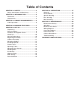
Table of Contents SECTION 1: SAFETY........................................ 2 Safety Instructions for Machinery................... 2 SECTION 2: INTRODUCTION........................... 5 Foreword......................................................... 5 Contact Info.................................................... 5 SECTION 3: CIRCUIT REQUIREMENTS......... 6 110V Operation............................................... 6 SECTION 4: MACHINE FEATURES................. 7 SECTION 5: Set UP....................
3%#4)/.
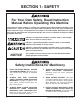
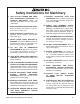
3AFETY )NSTRUCTIONS FOR -ACHINERY /.,9 !,,/7 42!).%$ !.$ 02/0 %2,9 350%26)3%$ 0%23/..%, 4/ /0%2!4% -!#().%29 BV`Z hjgZ deZgVi^dc ^chigjXi^dch VgZ hV[Z VcY XaZVgan jcYZghiddY# +%%0 #(),$2%. !.$ 6)3)4/23 !7!9 @ZZe Vaa X]^aYgZc VcY k^h^idgh V hV[Z Y^h" iVcXZ [gdb i]Z ldg` VgZV# -!+% 7/2+3(/0 #(),$02//& JhZ eVYadX`h! bVhiZg hl^iX]Zh! VcY gZbdkZ hiVgi hl^iX] `Znh# .%6%2 ,%!6% 7(%. -!#().% )3 25..).
Additional Safety Instructions For Oscillating Spindle & Disc Sander • • • • Read this manual. This manual contains proper operating instructions for this machine. do not jam the workpiece against the sanding surfaces. Firmly grasp the workpiece in both hands and ease it against the spindle/disc using light pressure. do not wear loose clothing while operating this machine. Roll up or button sleeves at the cuff. do not place hands near, or in contact with, sanding surfaces during operation.
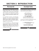
SECTION 2: INTRODUCTION Foreword Contact Info We are proud to offer the Model G0529 Oscillating Spindle & Disc Sander. This machine is part of a growing Grizzly family of fine woodworking machinery. When used according to the guidelines set forth in this manual, you can expect years of trouble-free, enjoyable operation and proof of Grizzly’s commitment to customer satisfaction. We stand behind our machines.
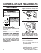
SECTION 3: CIRCUIT REQUIREMENTS 110V Operation Power Connection Device The Model G0529 comes with a 5-15 plug, similar to Figure 1, to connect the machine to power. Serious personal injury could occur if you connect the machine to power before completing the setup process. DO NOT connect the machine to the power until instructed later in this manual. Electrocution or fire could result if machine is not grounded and installed in compliance with electrical codes.
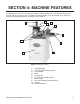
SECTION 4: MACHINE FEATURES An important part of safety is knowing your machine and its components. Take the time to familiarize yourself with the features of your new G0529 Oscillating Spindle & 12" Disc Sander. They will be frequently mentioned throughout the instructions in this manual. 2 1 3 4 5 6 10 7 8 9 Figure 2. Machine features. 1. Sanding Spindle 2. Cast Iron Spindle Sanding Table 3. Power Switch 4. Motor 5. Sanding Disc 6. Cast Iron Disc Sanding Table 7. Miter Gauge 8.
SECTION 5: Set UP Unpacking Parts Inventory The Model G0529 Oscillating Spindle & 12" Disc Sander was carefully packed at the factory. If you discover the machine is damaged after you have signed for delivery, and the truck and driver are gone, you will need to file a freight claim with the carrier. Save the containers and all packing materials for possible inspection by the carrier or its agent. Without the packing materials, filing a freight claim can be difficult.
Hardware Recognition Chart G0529 Oscillating Spindle & Disc Sander -9-
Clean Up Site Considerations The unpainted surfaces are coated with a waxy oil to protect them from corrosion during shipment. Remove this protective coating with a solvent cleaner or citrus-based degreaser such as Grizzly’s G7895 Degreaser. To clean thoroughly, some parts may need to be removed. For optimum performance from your machine, make sure you clean all moving parts or sliding contact surfaces that are coated.
Beginning Assembly Cabinet Assembly This section will cover the basic assembly and adjustment instructions needed to begin operation. Complete the assembly in the order provided in this manual and then read the remaining portion of the manual before attempting any type of operation. The Model G0529 Sander mounts on a sturdy cabinet stand. To assemble the cabinet stand: 1.
Mounting Sander When the cabinet has been completed, it is time to place the sander unit on top of the cabinet stand. To mount the sander to the top of the cabinet stand: 1. With the help of an assistant, place the sander on the cabinet stand. The Model G0529 weighs 166 lbs. Personal injury could occur if the machine is moved without additional assistance. Seek help when moving or lifting the machine. 2. Align the holes on the rim of the cabinet sides with the threaded holes in the rim of the sander. 3.
Table Inserts Squaring Table The table inserts minimize the gap between the working surface edge and the spindle. It is important to use the proper table insert according to the diameter spindle you are using. To square the sanding tables: 1. Disconnect the machine from the power supply. The Model G5029 comes with the following four table inserts: 2. Set the table at 90˚ as shown in Figure 8.
5. If the table is not 90˚ from the spindle, adjust the table stop bolt to allow the table to move more as shown in Figure 10. Figure 12. Squaring the disc sanding table. 3. Figure 11. Squaring the sanding table. 6. Tighten the table stop bolt against the underside of the table when the table is set at 90˚. Loosen the lock lever and adjust the table angle until it is perfectly perpendicular and flush with both edges of the machinist square. 4.
Sanding Disc Installation The disc sander requires 12" PSA (pressure sensitive adhesive) sanding discs. To install a new sanding disc on the 12" disc sanding surface: 1. Disconnect the machine from the power supply. Aligning Table The table must be spaced evenly away from the face of the sanding disc so that the sandpaper does not rub against the table. To align the table: 1. Loosen the bolts that secure the table to the table support bracket as shown in Figure 13. 2. Remove the disc sanding table. 3.
Miter Gauge Dust Collection The miter gauge needs to be adjusted perpendicular to the face of the wheel when it is mounted in the table slot. There are two 2" dust collection ports for the sander that should be connected to a dust collector. The ports are located under the sanding tables as shown in Figure 15. To adjust miter gauge: 1. Use a machinist square with one edge against the face of the miter gauge and the other against the disc face as shown in Figure 14. 2" Dust Ports Figure 16.
SECTION 6: Operations General Power Switch This section covers basic disc sanding operations. Please read the remaining portion of the manual before attempting any type of operation. The Model G0529 sander is equipped with a paddle-type power switch with a safety key. Your safety is important! Please follow the warnings below during this entire section: To operate the power switch: 1. Insert the safety locking key shown in Figure 16.
Spindle Sanding The oscillating spindle sander on the Model G0529 produces an extremely fine sanding finish on edges or contours. The oscillation of the spindle disperses the material contact throughout the sanding sleeve to prevent burning. Never use the Model G0529 for applications other than those for which it was made. DO NOT overload the machine or use excess force when sanding. Severe personal injury, damage to the machine, or damage to your workpiece could occur.
Miter Sanding Disc Sanding To perform disc sanding operations: 1. Set the angle of the table relative to the sanding disc. The angle can be set with the angle gauge on the disc sander or with a protractor for greater accuracy. The most efficient way to get a perfect miter is to cut the workpiece slightly long and sand it to the desired dimension.
SECTION 7: MAINTENANCE Maintenance Safety Schedule Your safety is important! Please follow the warnings below during this entire section: Check for the following conditions before you use the sander: • Loose table bolts. Serious personal injury could occur if you connect your machine to the power source during the maintenance process. DO NOT connect the machine to the power source while performing any maintenance on this machine. • Worn or damaged sanding discs or sleeves. • Worn or damaged wires.
SECTION 8: Reference Info Aftermarket Accessories PRO-STICK® Abrasive Surface Cleaners Extend the life of your sanding discs and sleeves! Size Model 11⁄2" X 11⁄2" X 81⁄2" ..................................... G1511 2" X 2" X 12".............................................
Machine Data Sheet MACHINE DATA SHEET Customer Service #: (570) 546-9663 · To Order Call: (800) 523-4777 · Fax #: (800) 438-5901 MODEL G0529 SPINDLE SANDER Product Dimensions: Weight.............................................................................................................................................................. 166 lbs. Length/Width/Height.............................................................................................................................
Spindle Info Spindle Diameters................................................................................................................1/4, 5/8, 1-1/2, 2 in. Spindle Lengths..................................................................................................................................... 5-1/2 in. Spindle Speed....................................................................................................................................1725 RPM Spindle Oscillations..............
Wiring Diagram The motor wiring shown here is current at the time of printing, but it may not match your machine. Always use the wiring diagram inside the motor junction box. CZjigVa =di E699A: HL>I8= k^ZlZY [gdb WZ]^cY DC 110 VAC D;;
Frame Breakdown +- +. +, ++ ,& ,&' -+ +' +* +) +( *+ ** *( )"& *' )"' )+ &&) +& (( )"( +'6 )* .& '. )) &%) '&%. ), ., .(+ &&) &% &&% &%% .. &%, &%- (. () && )& &%) (& ', .+ (- (, .* .) (* . &&' &&, &&* ,' ( ,( .' .& &(* &%& &%' &(& &(( &(+ (% &(' -- )' .( &&( (( &%( &&+ &%, &%- (+ -. &(- )% &(. ,+ -, .% )( )* + &%% -* , &&.
Frame Parts List REF PART # DESCRIPTION REF PART # DESCRIPTION 2 3 4 4-1 4-2 4-3 5 6 7 8 9 10 11 12 13 14 15 16 17 18 19 20 21 22 23 23-1 23-2 23-3 23-4 24 25 26 27 28 29 30 31 33 34 35 36 37 38 39 40 41 42 43 44 45 BASE UPPER FRAME SPINDLE 2" SPINDLE 1-1/2" SPINDLE 5/8" SPINDLE 1/4" HELICAL BEVEL GEAR PU HELICAL BEVEL GEAR RIGHT OIL BOX LEFT OIL BOX CONNECTION ROD RIGHT BRACKET LEFT BRACKET WORKING TABLE FLAT WASHER 3/8 WORKING TABLE FRONT GRADUATED SCALE REAR GRADUATED SCALE DUST HOOD DISC GUARD DISC
REF PART # DESCRIPTION REF PART # DESCRIPTION 110 112 113 114 115 116 117 118 119 121 COVER SET SCREW M4-.7 X 5 E-CLIP 4MM HEX BOLT M8-1.
Cabinet Breakdown &%+ &%- &%&%- -' -' -( &&+ &'+ -( &'* &'* &%- &)( -' &&+ -% -& &'+ &)% -% &)' &(, -& REF PART # DESCRIPTION REF PART # DESCRIPTION 80 81 82 83 106 108 116 PAD FLAT HD SCR 5/16-18 X 3/4 LOCK WASHER 5/16 HEX NUT 5/16-18 CAP SCREW 5/16-18 X 3/4 FLAT WASHER 5/16 HEX BOLT 5/16-18 X 1 125 126 137 140 142 143 RIGHT OR LEFT PANEL FRONT OR REAR PANEL WARNING LABEL-READ MANUAL WARNING LABEL-DUST MASK WARNING LABEL-ID LABEL GRIZZLY LOGO -28- P0529080 PFH14 PLW01 PN02
Troubleshooting Motor & Electrical Symptom Possible Cause Possible Solution Motor will not start. 1. Low voltage. 2. Open circuit in motor or loose connections. 1. Check power line for proper voltage. 2. Inspect all lead connections on motor for loose or open connections. Motor will not start; 1. Short circuit in line cord or plug. fuses or circuit breakers blow. 2. Short circuit in motor or loose connections. 1. Inspect cord or plug for damaged insulation and shorted wires. 2.
Machine Operation Continued Symptom Machine when operating. Possible Cause slows 1. Applying too much pressure to workpiece. Machine vibrates excessively. 2. Undersized circuit or using ext cord. 1. Stand not stable on floor. 2. Incorrect motor mounting. 3. Incorrect sanding sleeve tension. 4. Broken/defective sanding sleeve/disc. Possible Solution 1. Sand with less pressure—let the movement of the sleeve/disc do the work. 2. Make sure circuit wires are proper gauge & don’t use ext cords! 1.
7!22!.
;DA9 6ADC< 9DII:9 A>C: EaVXZ HiVbe =ZgZ '2)::,9 ).$5342)!, ).# 0 / "/8 "%,,).
WARRANTY AND RETURNS 7!22!.49 !.$ 2%452.
"UY $IRECT AND 3AVE WITH 'RIZZLY® n 4RUSTED 0ROVEN AND A 'REAT 6ALUE 6ISIT /UR 7EBSITE 4ODAY !ND $ISCOVER 7HY 'RIZZLY® )S 4HE )NDUSTRY ,EADER s 3%#52% /2$%2).' s /2$%23 3()00%$ 7)4(). (/523 s % -!), 2%30/.3% 7)4(). /.