OSCILLATING SPINDLE & 12" DISC SANDER MODEL G0529 INSTRUCTION MANUAL COPYRIGHT © SEPTEMBER, 2003 BY GRIZZLY INDUSTRIAL, INC. WARNING: NO PORTION OF THIS MANUAL MAY BE REPRODUCED IN ANY SHAPE OR FORM WITHOUT THE WRITTEN APPROVAL OF GRIZZLY INDUSTRIAL, INC. PRINTED IN TAIWAN ONLINE MANUAL DISCLAIMER THE INFORMATION IN THIS MANUAL REPRESENTS THE CONFIGURATION OF THE MACHINE AS IT IS CURRENTLY BEING SHIPPED. THE MACHINE CONFIGURATION CAN CHANGE AS PRODUCT IMPROVEMENTS ARE INCORPORATED.
WARNING Some dust created by power sanding, sawing, grinding, drilling, and other construction activities contains chemicals known to the State of California to cause cancer, birth defects or other reproductive harm. Some examples of these chemicals are: • Lead from lead-based paints. • Crystalline silica from bricks, cement, and other masonry products. • Arsenic and chromium from chemically treated lumber. Your risk from these exposures varies, depending on how often you do this type of work.
Table of Contents SECTION 1: SAFETY............................................................................................................................2 Safety Instructions For Power Tools ..............................................................................................2 SECTION 2: INTRODUCTION ..............................................................................................................5 SECTION 3: CIRCUIT REQUIREMENTS ...................................................
SECTION 1: SAFETY For Your Own Safety Read Instruction Manual Before Operating This Equipment The purpose of safety symbols is to attract your attention to possible hazardous conditions. This manual uses a series of symbols and signal words which are intended to convey the level of importance of the safety messages. The progression of symbols is described below. Remember that safety messages by themselves do not eliminate danger and are not a substitute for proper accident prevention measures.
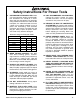
Safety Instructions For Power Tools 9. USE PROPER EXTENSION CORD. Make sure your extension cord is in good condition. Conductor size should be in accordance with the chart below. The amperage rating should be listed on the motor or tool nameplate. An undersized cord will cause a drop in line voltage resulting in loss of power and overheating. Your extension cord must also contain a ground wire and plug pin. Always repair or replace extension cords if they become damaged.
Additional Safety Instructions For The Oscillating Spindle & Disc Sander • • • • READ THIS MANUAL. This manual contains proper operating instructions for this machine. DO NOT jam the workpiece against the sanding surfaces. Firmly grasp the workpiece in both hands and ease it against the spindle/disc using light pressure. DO NOT wear loose clothing while operating this machine. Roll up or button sleeves at the cuff. REPLACE sanding discs and sleeves when they become worn.
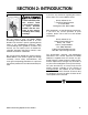
SECTION 2: INTRODUCTION If you have any comments regarding this manual, please write to us at the address below: Lack of familiarity with this manual could cause serious personal injury. Become familiar with the contents of this manual, including all the safety warnings. We are proud to offer the Model G0529 Oscillating Vertical Spindle Sander & 12" Disc Sander. This machine is part of a growing Grizzly family of fine woodworking machinery.
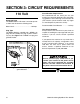
SECTION 3: CIRCUIT REQUIREMENTS 110 Volt Amperage Draw The Model G0529 1 HP motor is wired to operate at 110V and will draw the following load: Motor Load............................................10 Amps Plug Type The Model G0529 is supplied with a NEMA 5-15 plug. DO NOT modify the plug or power cord in any way. See Figure 1 for a NEMA 5-15 plug and grounded outlet. Circuit Breaker Requirements We recommend that the circuit you use your machine on should be dedicated.
Grounding Extension Cords In the event of an electrical short, grounding reduces the risk of electric shock by providing a path of least resistance to disperse electric current. This tool is equipped with a power cord that has an equipment-grounding prong. The outlet must be properly installed and grounded in accordance with all local codes and ordinances.
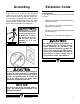
SECTION 4: MACHINE FEATURES An important part of safety is knowing your machine and its components. Take the time to familiarize yourself with the features of your new G0529 Oscillating Spindle & 12" Disc Sander. They will be frequently mentioned throughout the instructions in this manual. 2 1 3 4 5 6 10 7 8 9 Figure 2. Machine Features. 1. 2. 3. 4. 5. 6. 7. 8. 9. 10.
SECTION 5: SET UP Unpacking Parts Inventory The Model G0529 Oscillating Spindle & 12" Disc Sander was carefully packed at the factory. If you discover the machine is damaged after you have signed for delivery, and the truck and driver are gone, you will need to file a freight claim with the carrier. Save the containers and all packing materials for possible inspection by the carrier or its agent. Without the packing materials, filing a freight claim can be difficult.
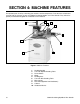
10 WASH Button Head Screw Flange Bolt ⁄ '' 7 16 23⁄4'' 3 WASH S WA H ASH 8mm ASH W ASHE 6mm DI ER ASH ASHE R DIA ⁄ '' 14 D ER I ASH 21⁄2'' DIA ER ⁄ '' 5 16 ET AM LINES ARE 1⁄16'' INCH APART LINES ARE 1MM APART 21⁄4'' 10mm R DIA ET AM 2 4mm MET 13⁄4'' ⁄ '' 38 METE 11⁄2'' D ER IA TE ME R 16mm ⁄ '' ⁄ '' ⁄ '' ⁄ '' ⁄ '' 1'' 11⁄4'' 5 16 7 16 9 16 34 78 MET 12mm '' '' '' '' ET AM 10mm ⁄ ⁄ ⁄ ⁄ 14 38 12 58 DI ER ETER M 8mm 5mm 10mm 15mm 20mm 25mm 30mm 35mm 40mm 4
Clean Up Site Considerations The unpainted surfaces are coated with a waxy oil to protect them from corrosion during shipment. Remove this protective coating with a solvent cleaner or citrus-based degreaser such as Grizzly’s G7895 Degreaser. To clean thoroughly, some parts may need to be removed. For optimum performance from your machine, make sure you clean all moving parts or sliding contact surfaces that are coated.
Beginning Assembly Cabinet Assembly This section will cover the basic assembly and adjustment instructions needed to begin operation. Complete the assembly in the order provided in this manual and then read the remaining portion of the manual before attempting any type of operation. The Model G0529 Sander mounts on a sturdy cabinet stand. To assemble the cabinet stand: 1.
Mounting Sander When the cabinet has been completed, it is time to place the sander unit on top of the cabinet stand. To mount the sander to the top of the cabinet stand: 1. 3. To install the spindle onto the sander: 1. Disconnect the machine from the power supply. 2. Select the proper diameter of spindle sleeve. The Model G5029 comes with the following four sizes of spindle sleeves: With the help of an assistant, place the sander on the cabinet stand. The Model G0529 weighs 143 lbs.
Table Inserts Squaring Table The table inserts minimize the gap between the working surface edge and the spindle. It is important to use the proper table insert according to the diameter spindle you are using. To square the sanding tables: 1. Disconnect the machine from the power supply. The Model G5029 comes with the following four table inserts: 2. Set the table at 90˚ as shown in Figure 8.
If the table is not 90˚ from the spindle, adjust the table stop bolt to allow the table to move more as shown in Figure 10. 5. ! Figure 11. Squaring the sanding table. 3. Loosen the lock lever and adjust the table angle until it is perfectly perpendicular and flush with both edges of the machinist square. 4. Tighten the lock lever while holding the table perpendicular. 5. Adjust the scale pointer to read 0˚ when the table has been properly adjusted. Figure 10. Squaring the sanding table. 6.
Sanding Disc Installation Aligning Table The disc sander requires 12" sanding discs with hook and loop backing. To install a new sanding disc on the 12" disc sanding surface: 1. Disconnect the machine from the power supply. 2. Remove the disc sanding table. 3. Remove the old sanding disc. 4. Install the new sanding disc as shown in Figure 12. The table must be aligned to the face of the sanding disc so that the sandpaper does not rub against the table. To align the table: 1.
Miter Gauge Dust Collection The miter gauge needs to be adjusted perpendicular to the face of the wheel when it is mounted in the table slot. There are two 2" dust collection ports for the sander that should be connected to a dust collector. The ports are located under the sanding tables as shown in Figure 15. To adjust miter gauge: 1. Use a machinist square with one edge against the face of the miter gauge and the other against the disc face as shown in Figure 14. ! 2" Dust Ports Figure 15.
SECTION 6: OPERATIONS General Power Switch This section covers basic disc sanding operations. Please read the remaining portion of the manual before attempting any type of operation. The Model G0529 sander is equipped with a paddle-type power switch with a safety key. Your safety is important! Please follow the warnings below during this entire section: To operate the power switch: 1. Insert the safety locking key shown in Figure 16.
Spindle Sanding The oscillating spindle sander on the Model G0529 produces an extremely fine sanding finish on edges or contours. The oscillation of the spindle disperses the material contact throughout the sanding sleeve to prevent burning. Never use the Model G0529 for applications other than those for which it was made. DO NOT overload the machine or use excess force when sanding. Severe personal injury, damage to the machine, or damage to your workpiece could occur.
Miter Sanding Disc Sanding To perform disc sanding operations: 1. Set the angle of the table relative to the sanding disc. The angle can be set with the angle gauge on the disc sander or with a protractor for greater accuracy. The most efficient way to get a perfect miter is to cut the workpiece slightly long and sand it to the desired dimension.
SECTION 7: MAINTENANCE Maintenance Safety Schedule Your safety is important! Please follow the warnings below during this entire section: Check for the following conditions before you use the sander: • Loose table bolts. ! Serious personal injury could occur if you connect your machine to the power source during the maintenance process. DO NOT connect the machine to the power source while performing any maintenance on this machine. • Worn or damaged sanding discs or sleeves. • Worn or damaged wires.
Maintenance Log Date -22- Approximate Hours Of Use Maintenance Performed G0529 Oscillating Spindle & Disc Sander
SECTION 8: REFERENCE INFO General This section contains the following subsections for the Model G0529: aftermarket accessories, data sheets, parts diagrams and list, troubleshooting, and warranty/return information. If you need parts or help in assembling your machine, or if you need operational information, call the service department at (570) 546-9663. Trained service technicians will be glad to help you.
MACHINE DATA SHEET Customer Service #: (570) 546-9663 • To Order Call: (800) 523-4777 • Fax #: (800) 438-5901 G0529 OSCILLATING SPINDLE & 12" DISC SANDER Design Type ......................................................................................................Floor Model Overall Dimensions: Height ....................................................................................................................47"H Height (Spindle Table to Floor)....................................................
Parts Diagrams & Lists 66 71 78 12 86 67 65 64 63 52 46 114 61 33 104 28 109 45 91 29 114 44 10 110 97 98 36 100 99 107 108 39 34 96 38 37 95 94 35 9 11 41 112 104 31 33 36 93 92 91 113 27 135 103 116 107 108 117 115 101 102 3 131 133 136 30 132 88 42 89 138 40 139 76 87 90 43 45 6 100 85 7 119 107 108 4 60 13 75 25 23-4 8 5 84 118 141 23 116 108 24 23-1 23-3 14 23-2 116 108 22 21 19 2 117 107 106 22 124 G0529 Oscillating Spindle & Disc Sander 121
Parts Diagrams & Lists 106 108 108 108 82 82 83 126 116 83 125 125 108 143 82 116 80 81 126 140 80 142 -26- 137 81 G0529 Oscillating Spindle & Disc Sander
REF PART # 2 3 4 5 6 7 8 9 10 11 12 13 14 15 16 17 18 19 20 21 22 23 23-1 23-2 23-3 23-4 24 25 26 27 28 29 30 31 32 33 34 35 36 37 38 39 40 41 42 43 44 45 46 P0529002 P0529003 P0529004 P0529005 P0529006 P0529007 P0529008 P0529009 P0529010 P0529011 P0529012 PW02 P0529014 P0529015 P0529016 P0529017 P0529018 P0529019 P0529020 P0529021 P0529022 P0529023 P0529023-1 P0529023-2 P0529023-3 P0529023-4 P0529024 PSW07 P0529026 P0529027 P0529028 P0529029 P0529030 P0529031 PSS11 P0529033 P0529034 P0529035 P0529036 P6
REF PART # 104 106 107 108 109 110 112 113 114 115 116 117 118 119 120 121 123 PW06 PSB07 PLW01 PW07 PSB33M P0529110 PSS08M PEC02M PB07M PSS02M PB03 PS06 PN01M PB04 PLN03 PB19 P0529123 -28- DESCRIPTION REF FLAT WASHER 1⁄4 CAP SCREW 5⁄16-18 X 3⁄4 LOCK WASHER 5⁄16 FLAT WASHER 5⁄16 CAP SCREW M5-.8 X 12 COVER SET SCREW M4-.7 X 5 E-CLIP 4MM HEX BOLT M8-1.
Troubleshooting TROUBLE CAUSE CORRECTION Grains easily rub off the 1. Sanding sleeve/disc has been stored in 1. Store sanding sleeve/disc away from extremely hot or dry temsleeve or disc . an incorrect environment. peratures. 2. Sanding sleeve/disc has been smashed 2. Store sanding sleeve/disc flat not bent or folded. or folded. Deep sanding grooves or 1. Sanding sleeve/disc grit is too coarse scars in workpiece. for the desired finish. 2. Workpiece sanded across the grain. 3.
Warranty & Returns Grizzly Industrial, Inc. warrants every product it sells for a period of 1 year to the original purchaser from the date of purchase. This warranty does not apply to defects due directly or indirectly to misuse, abuse, negligence, accidents, repairs or alterations or lack of maintenance.
WARRANTY CARD Name ____________________________________________________________________________________ Street ____________________________________________________________________________________ City ______________________________________________________________State________Zip_________ Phone Number_______________________E-Mail_______________________FAX________________________ Model #_____________________Serial # __________________________ Order #______________________ The following information is given on
FOLD ALONG DOTTED LINE Place Stamp Here GRIZZLY INDUSTRIAL, INC. P.O.
Buy Direct and Save with Grizzly® – Trusted, Proven and a Great Value! Visit Our Website Today And Discover Why Grizzly® Is The Industry Leader! • SECURE ORDERING • ORDERS SHIPPED WITHIN 24 HOURS • E-MAIL RESPONSE WITHIN ONE HOUR -OR- Call Today For A FREE Full Color Catalog