MODEL G0538 OSCILLATING SPINDLE SANDER OWNER'S Manual Copyright © NOVEMBER, 2005 By Grizzly Industrial, Inc. Revised December, 2009 (JB) Warning: No portion of this manual may be reproduced in any shape Or form without the written approval of Grizzly Industrial, inc.
This manual provides critical safety instructions on the proper setup, operation, maintenance and service of this machine/equipment. Failure to read, understand and follow the instructions given in this manual may result in serious personal injury, including amputation, electrocution or death. The owner of this machine/equipment is solely responsible for its safe use.
Table of Contents INTRODUCTION................................................................................................................................ 2 Foreword..................................................................................................................................... 2 Contact Info................................................................................................................................. 2 Machine Data Sheet............................................
INTRODUCTION Foreword Contact Info We are proud to offer the Model G0538 Oscillating Spindle Sander. This machine is part of a growing Grizzly family of fine woodworking machinery. When used according to the guidelines set forth in this manual, you can expect years of trouble-free, enjoyable operation and proof of Grizzly’s commitment to customer satisfaction.
Machine Data Sheet MACHINE DATA SHEET Customer Service #: (570) 546-9663 · To Order Call: (800) 523-4777 · Fax #: (800) 438-5901 MODEL G0538 1/3 HP OSCILLATING SPINDLE SANDER Product Dimensions: Weight................................................................................................................................................................ 34 lbs. Length/Width/Height.......................................................................................................................
Machine Data Sheet Spindle Info Spindle Diameters........................................................................................................1/2, 3/4, 1, 1-1/2, 2, 3 in. Spindle Lengths..................................................................................................................................... 4-1/2 in. Spindle Speed....................................................................................................................................
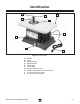
Identification A B D C E G F H I Figure 1. Identification. A. B. C. D. E. F. G. H. I. J.
SECTION 1: SAFETY For Your Own Safety, Read Instruction Manual Before Operating this Machine The purpose of safety symbols is to attract your attention to possible hazardous conditions. This manual uses a series of symbols and signal words which are intended to convey the level of importance of the safety messages. The progression of symbols is described below. Remember that safety messages by themselves do not eliminate danger and are not a substitute for proper accident prevention measures.
Safety Instructions for Machinery 7. Only allow trained and properly supervised personnel to operate machinery. Make sure operation instructions are safe and clearly understood. 8. KEEP CHILDREN AND VISITORS AWAY. Keep all children and visitors a safe distance from the work area. 9. MAKE WORKSHOP CHILD PROOF. Use padlocks, master switches, and remove start switch keys. 10. NEVER LEAVE WHEN MACHINE IS RUNNING.
Safety Instructions for Spindle Sanders 1. FEED RATE. Never jam a workpiece against the sanding surface. Firmly hold the workpiece and ease it against the spindle using light pressure. 7. SANDING SLEEVES. Worn or damaged sanding sleeves can tear apart and become entangled in the spindle. Replace sanding sleeves promptly as required. 2. AVOIDING ENTANGLEMENT. Keep loose clothing articles such as sleeves, belts or jewelry items away from the spindle. Never wear gloves when operating the spindle sander.
SECTION 2: CIRCUIT REQUIREMENTS 110V Operation Serious personal injury could occur if you connect the machine to the power source before you have completed the set up process. DO NOT connect the machine to the power source until instructed to do so. Electrocution or fire could result if this machine is not grounded correctly or if your electrical configuration does not comply with local and state codes.
SECTION 3: SET UP Set Up Safety This machine presents serious injury hazards to untrained users. Read through this entire manual to become familiar with the controls and operations before starting the machine! Wear safety glasses during the entire set up process! Items Needed for Set Up The following items are needed to complete the set up process, but are not included with your machine: Description Qty • Safety Glasses (for each person)............... 1 • Dust Collection System...........................
Inventory After all the parts have been removed from the box, you should have the following items: A Inventory (Figure 3) Qty A. Sander Unit................................................. 1 B. Sander Unit Base Plate............................... 1 C. Sanding Sleeve and Drum 3"...................... 1 D. Sanding Sleeve and Drum 2"...................... 1 E. Sanding Sleeve and Drum 11⁄2"................... 1 F. Sanding Sleeve and Drum 3⁄4"..................... 1 G. Sanding Sleeve 1⁄2"....................
Base Attachment The metal base plate needs to be attached to the spindle sander before use. Components and Hardware Needed: Qty Tap Screw M4-0.7 x 12...................................... 4 Sander Base Plate............................................. 1 To attach the sander base plate: 1. Examine the inside of the sander body and remove any loose packing material found. Figure 5. Mounting the spindle sander. Note: Loose packing material inside the sander body during operation is an imminent fire hazard.
SECTION 4: OPERATIONS Switch⁄Safety Key Keep loose clothing rolled up and out of the way of machinery and keep hair pulled back. To disable the switch, remove the lockout key (Figure 7) from the paddle switch. Disconnect power from the machine when performing any maintenance, assembly or adjustments. Failure to do this may result in serious personal injury. Using this machine produces dust which may cause allergic reactions and respiratory problems.
To install or replace a sanding sleeve: 1. Hold the spindle hex nut with one of the included 9⁄16" wrenches. 2. Hold the flats of the spindle using the small slot in the second 9⁄16" wrench, as shown in Figure 8, and loosen the hex nut so that it can be removed by hand. Figure 9. Sleeve installation order. Sanding To sand a workpiece: Figure 8. Loosening the spindle hex nut. 3. Remove the hex nut, upper spindle washer, sanding sleeve, sanding drum, and throat plate. 4.
SECTION 5: ACCESSORIES G7984—Face Shield H1298—Dust Sealed Safety Glasses H1300—UV Blocking, Clear Safety Glasses H2347—Uvex® Spitfire Safety Glasses H0736—Shop Fox® Safety Glasses H1300 H1298 G7984 H2347 H0736 Figure 11. Our most popular safety glasses. PRO-STIK® Belt Cleaners G1511—Large (11 ⁄ 2" x 11 ⁄ 2" x 81 ⁄ 2") G1512—Small (2" x 2" x 12") H1446—13 ⁄ 8" x 41 ⁄4" H1447—13 ⁄ 8" x 81 ⁄ 2" These crepe-rubber Belt Cleaners quickly remove gum and grit from belts and discs without damage.
SECTION 6: MAINTENANCE Cleaning Disconnect power from the machine when performing any maintenance, assembly or adjustments. Failure to do this may result in serious personal injury. Schedule Cleaning the Model G0538 is relatively easy. Follow the Sleeve Installation instructions on Page 15, taking special care to clean every area thoroughly. However, sawdust and other particles can also work their way under the rotation mark plate. To clean under the rotation mark plate: 1.
SECTION 7: SERVICE Review the troubleshooting and procedures in this section to fix your machine if a problem develops. If you need replacement parts or you are unsure of your repair skills, then feel free to call our Technical Support at (570) 546-9663. Troubleshooting Motor & Electrical Symptom Possible Cause Possible Solution 1. Check power line voltage and correct if necessary. Motor will not start. 1. Low voltage. 2. Open circuit in motor or loose connec- 2.
Burn marks workpiece. on 1. Using too fine of sanding grit. 2. Using too much pressure. 3. Work held still for too long. Glazed sanding 1. Sanding wet stock. surfaces. 2. Sanding stock with high residue. 1. Use a coarser grit sanding sleeve. 2. Reduce pressure on workpiece while sanding. 3. Do not keep workpiece in one place for too long. 1. Dry stock properly before sanding. 2. Use different stock. Or, accept the characteristics of the stock and plan on cleaning⁄replacing belts⁄discs frequently.
Wiring Diagram 110 VOLT MOTOR Disconnect power from machine before performing any electrical service.
74 -20- 65 61 64 5 4-3 75 2 1 66 3 76 63 68 67 14 8 69 4-1 70 71 20 7 6 13 72 23 22 62 73 21 18 4-2 19 12 53 57 54 4-6 53 55 56 58 60 15 17 59 16 57 54 55 4-4 4-5 11 9 10 48 31 47 30 52 32 37 45 51 35 49 50 46 44 29 28 27 26 38 39 40 42 41 33 34 35 36 32 25 24 43 Parts Breakdown G0538 Oscillating Spindle Sander
Parts List REF PART # DESCRIPTION REF PART # DESCRIPTION 1 2 3 4-1 4-2 4-3 4-4 4-5 4-6 5 6 7 8 9 10 11 12 13 14 15 16 17 18 19 20 21 22 23 24 25 26 27 28 29 30 31 32 33 34 35 36 PN03M P0538002 P0538003 P0538004-1 P0538004-2 P0538004-3 P0538004-4 P0538004-5 P0538004-6 P0538005 P0538006 PHTEK22M P0538008 P0538009 P0538010 PHTEK5M P0538012 P0538013 P0538014 PHTEK6M P0538016 P0538017 P0538018 P0538019 PW03M PHTEK17M P0538022 PHTEK5M PHTEK6M P0538025 P0538026 P0538027 P0538028 PHTEK6M P0538030 PK19M P0538
WARRANTY AND RETURNS Grizzly Industrial, Inc. warrants every product it sells for a period of 1 year to the original purchaser from the date of purchase. This warranty does not apply to defects due directly or indirectly to misuse, abuse, negligence, accidents, repairs or alterations or lack of maintenance.
WARRANTY CARD Name _____________________________________________________________________________ Street _____________________________________________________________________________ City _______________________ State _________________________ Zip _____________________ Phone # ____________________ Email ________________________ Invoice # _________________ Model # ____________________ Order # _______________________ Serial # __________________ The following information is given on a voluntary basis.
FOLD ALONG DOTTED LINE Place Stamp Here GRIZZLY INDUSTRIAL, INC. P.O.
Buy Direct and Save with Grizzly ® – Trusted, Proven and a Great Value! ~Since 1983~ Visit Our Website Today For Current Specials! ORDER 24 HOURS A DAY! 1-800-523-4777