4" X 36" BELT & 6" DISC COMBO SANDER MODEL G0547 INSTRUCTION MANUAL COPYRIGHT © NOVEMBER, 2003 BY GRIZZLY INDUSTRIAL, INC. WARNING: NO PORTION OF THIS MANUAL MAY BE REPRODUCED IN ANY SHAPE OR FORM WITHOUT THE WRITTEN APPROVAL OF GRIZZLY INDUSTRIAL, INC. ONLINE MANUAL DISCLAIMER THE INFORMATION IN THIS MANUAL REPRESENTS THE CONFIGURATION OF THE MACHINE AS IT IS CURRENTLY BEING SHIPPED. THE MACHINE CONFIGURATION CAN CHANGE AS PRODUCT IMPROVEMENTS ARE INCORPORATED.
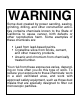
WARNING Some dust created by power sanding, sawing, grinding, drilling, and other construction activities contains chemicals known to the State of California to cause cancer, birth defects or other reproductive harm. Some examples of these chemicals are: • Lead from lead-based paints. • Crystalline silica from bricks, cement, and other masonry products. • Arsenic and chromium from chemically treated lumber. Your risk from these exposures varies, depending on how often you do this type of work.
Table of Contents SECTION 1: SAFETY ..................................................................................................................................2 Safety Instructions for Power Tools ......................................................................................................2 Additional Safety Instructions for the G0547 Combo Sander................................................................4 SECTION 2: INTRODUCTION .........................................................
SECTION 1: SAFETY For Your Own Safety Read Instruction Manual Before Operating This Equipment The purpose of safety symbols is to attract your attention to possible hazardous conditions. This manual uses a series of symbols and signal words which are intended to convey the level of importance of the safety messages. The progression of symbols is described below. Remember that safety messages by themselves do not eliminate danger and are not a substitute for proper accident prevention measures.
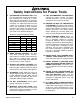
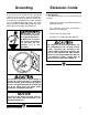
Safety Instructions for Power Tools 9. USE PROPER EXTENSION CORD. Make sure your extension cord is in good condition. Conductor size should be in accordance with the chart below. The amperage rating should be listed on the motor or tool nameplate. An undersized cord will cause a drop in line voltage resulting in loss of power and overheating. Your extension cord must also contain a ground wire and plug pin. Always repair or replace extension cords if they become damaged.
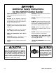
Additional Safety Instructions for the G0547 Combo Sander • • • • READ THIS MANUAL. This manual contains proper operating instructions for this machine. DO NOT jam the workpiece against the sanding surfaces. Firmly grasp the workpiece in both hands and ease it against the belt/disc using light pressure. DO NOT wear loose clothing while operating this machine. Roll up or button sleeves at the cuff. REPLACE sanding discs and belts when they become worn.
SECTION 2: INTRODUCTION If you have any comments regarding this manual, please write to us at the address below: Lack of familiarity with this manual could cause serious personal injury. Become familiar with the contents of this manual, including all the safety warnings. We are proud to offer the Model G0547 4" x 36" Belt & 6" Disc Combo Sander. This machine is part of a growing Grizzly family of fine woodworking machinery.
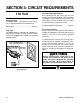
SECTION 3: CIRCUIT REQUIREMENTS 110 Volt Amperage Draw The Model G0547 1⁄3 HP motor is wired to operate at 110V and will draw the following load: Motor Load..............................................5 Amps Plug Type The Model G0547 is supplied with a NEMA 5-15 plug. DO NOT modify the plug or power cord in any way. See Figure 1 for a NEMA 5-15 plug and grounded outlet. i Circuit Breaker Requirements We recommend that the circuit you use your machine on should be dedicated.
Grounding Extension Cords In the event of an electrical short, grounding reduces the risk of electric shock by providing a path of least resistance to disperse electric current. This tool is equipped with a power cord that has an equipment-grounding prong. The outlet must be properly installed and grounded in accordance with all local codes and ordinances.
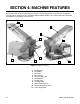
SECTION 4: MACHINE FEATURES An important part of safety is knowing your machine and its components. Take the time to familiarize yourself with the features of your new Model G0547 Combo Sander. They will be frequently mentioned throughout the instructions in this manual. 8 9 1 2 10 6 11 7 3 5 4 Figure 2. Machine Features. 1. 2. 3. 4. 5. 6. 7. 8. 9. 10. 11.
SECTION 5: SET UP Unpacking The machine was carefully packed when it left the Grizzly warehouse. If you discover the machine is damaged after you have signed for delivery, and the truck and driver are gone, you will need to file a freight claim with the carrier. Save the containers and all packing materials for possible inspection by the carrier or its agent. Without the packing materials, filing a freight claim can be difficult.
Hardware Recognition Chart -10- G0547 Combo Sander
Site Considerations Weight Load The Model G0547 Combo Sander is a small weight load with a small footprint. Most tables and workbenches should be sufficient to carry the weight of the machine. Reinforce the table or workbench if you question its ability to support the added weight. Working Clearance Working clearances can be thought of as the distances between machines and obstacles that allow safe operation of every machine without limitation.
Beginning Assembly This section will cover the basic assembly and adjustment instructions needed to begin operation. Complete the assembly in the order provided in this manual and then read the remaining portion of the manual before attempting any type of operation. Mounting Sander To mount the sander to a workbench: 1. Screw 1⁄4" x 11⁄2" (or longer) lag bolts with 1⁄4" washers through the holes in the base and into the workbench.
Installing Disc Table To install the disc table: 1. Lay the table upside down and align the table support with the holes in the table. 2. Take three hex bolts out of the hardware bag and put a lock washer and a flat washer on each bolt. 3. Screw the hex bolts with washers through the table support and into the disc table as shown in Figure 5. Squaring Table When the table tilt is set to 0˚, the table should be adjusted perpendicular to the sanding disc face. To square the table: 1.
Attaching Sandpaper 5. Center the sticky half of the sandpaper on the upper half of the disc and press the sandpaper onto the surface (Figure 8). ! The Model G0547 Combo Sander accepts 6" diameter cloth or paper-backed pressure sensitive adhesive (PSA) sanding discs. These are available in a variety of grits. See the current Grizzly catalog for prices and ordering information.
Aligning Table Adjusting Miter Gauge The table must be aligned to the face of the sanding disc so that the sandpaper does not rub against the table. To align the table: 1. 2. 3. Disconnect the machine from the power source! Loosen the hex bolts that secure the table to the table support bracket. The miter gauge needs to be adjusted perpendicular to the face of the wheel when it is mounted in the table slot. To adjust miter gauge: 1. Disconnect the machine from the power source! 2.
Installing Sanding Belt Adjusting Belt Angle To adjust the sanding belt angle: 1. Disconnect the machine from the power source! 2. Loosen the cap screw shown in Figure 11. ! To install the sanding belt: 1. Disconnect the machine from the power source! 2. Loosen the belt tension by pulling out the tensioning lever shown in Figure 13. ! Belt Tensioning Lever Figure 11. Raising the sanding belt bed. 3. Raise the sanding belt to the desired angle and tighten the cap screw. Figure 13.
Adjusting Sanding Belt Tracking Before starting the sander, make sure you have performed the preceding assembly and adjustment instructions, and you have read through the rest of the manual and are familiar with the various functions and safety issues associated with this machine. Failure to follow this warning could result in serious personal injury. 5. Note—Listen for any unusual noises, vibrations or rubbing while adjusting the tracking. If anything sounds unusual, stop the sander immediately.
SECTION 6: OPERATIONS Power Switch General This section covers basic sanding operations. Please read the remaining portion of the manual before attempting any type of operation. The Model G0547 Combo Sander is equipped with a paddle-type power switch with a safety key.
Disc Sanding Always keep the workpiece on the side of the wheel that is rotating down toward the table. This will keep the workpiece from flying out of your hands from the rotational forces. Miter Sanding The most efficient way to get a perfect miter is to cut the workpiece slightly long and sand it to the desired dimension. Miter sanding can be done easily with the miter gauge: To perform miter sanding operations: 1.
Angle Sanding Miters can also be sanded by changing the angle of the table. Always keep the workpiece on the side of the wheel that is rotating down toward the table. This will keep the workpiece from flying out of your hands from the rotational forces. To perform angle sanding operations: 1. Loosen the knob securing the table. 2. Use the angle gauge to acheive the desired table angle and tighten the handles.
Horizontal Sanding Curved Sanding Horizontal sanding allows you to sand the flat surface of a board. Inside curves can be sanded using the curved end of the sanding belt. To perform horizontal sanding operations: To perform curved sanding operations: 1. Turn the power ON and allow the sander to reach full speed. 1. Turn the power ON and allow the sander to reach full speed. 2. Place the workpiece against the surface of the sanding belt.
SECTION 7: MAINTENANCE Maintenance Safety Schedule Your safety is important! Please follow the warnings below during this entire section: Check for the following conditions before each use: • Loose table bolts. ! Serious personal injury could occur if you connect your machine to the power source during the maintenance process. DO NOT connect the machine to the power source while performing any maintenance on this machine. • Worn or damaged sanding discs or belts. • Worn or damaged wires.
Replacing Drive Belt 6. Tighten the drive belt housing screws while keeping tension on the drive belt. 7. Test the belt tension by squeezing the belt between your fingers. There should be no more than 1⁄4" of play in the belt. To replace and tension the drive belt: 1. Disconnect the machine from the power source! 2. Remove the drive belt cover plate. 3. Loosen the three screws shown in Figure 23 and slide the drive belt housing down and remove the old belt.
SECTION 8: REFERENCE INFO General This section contains the following subsections for the Model G0547: aftermarket accessories, data sheets, parts diagrams and list, troubleshooting, and warranty/return information. If you need parts or help in assembling your machine, or if you need operational information, call the service department at (570) 546-9663. Trained service technicians will be glad to help you.
MACHINE DATA SHEET Customer Service #: (570) 546-9663 • To Order Call: (800) 523-4777 • Fax #: (800) 438-5901 GRIZZLY MODEL G0547 4" X 36" BELT 6" DISC COMBO SANDER Design Type.................................................................................................... Bench Model Overall Dimensions and Specifications: Height (Belt Horizontal) ........................................................................................103⁄4" Height (Belt Vertical) ........................................
Parts Breakdown -26- G0547 Combo Sander
REF PART # 1 2 3 4 5 6 7 8 9 10 11 12 13 14 15 16 17 18 19 20 21 22 23 24 25 26 27 28 29 30 31 32 33 34 35 36 37 38 P0547001 P0547002 P0547003 P0547004 PS75M PB02M PLW03M PW03M P0547009 P0547010 PLW01M PS09M P0547013 PSS16M P0547015 P6001 P0547017 P0547018 PW02M PS05M P0547021 P0547022 PS06M PHTEK28M P0547025 P0547026 P0547027 PSB26M PLW03M P0547030 PHTEK4M P0547032 P0547033 P0547034 P0547035 P0547036 P0547037 P0547038 DESCRIPTION KNOB M6-1 X 27 (MALE) RUBBER WASHER NOTCHED WASHER BED PHLP HD SCR M5-.
Troubleshooting Guide TROUBLE CAUSE CORRECTION Grains easily rub off the belt 1. Sanding belt/disc has been stored in an 1. Store sanding belt/disc away from extremely hot or dry temperor disc. incorrect environment. atures. 2. Sanding belt/disc has been smashed or 2. Store sanding belt/disc flat not bent or folded. folded. Deep sanding grooves or 1. Sanding belt/disc grit is too coarse for scars in workpiece. the desired finish. 2. Workpiece sanded across the grain. 3.
Maintenance Notes Date Approximate Hours Of Use G0547 Combo Sander Service Performed -29-
Warranty & Returns Grizzly Industrial, Inc. warrants every product it sells for a period of 1 year to the original purchaser from the date of purchase. This warranty does not apply to defects due directly or indirectly to misuse, abuse, negligence, accidents, repairs or alterations or lack of maintenance.
WARRANTY CARD Name ____________________________________________________________________________________ Street ____________________________________________________________________________________ City ______________________________________________________________State________Zip_________ Phone Number_______________________E-Mail_______________________FAX________________________ Model # G0547 Combo Sander Serial # __________________________ Order #______________________ The following information is given on
FOLD ALONG DOTTED LINE Place Stamp Here GRIZZLY INDUSTRIAL, INC. P.O.
Buy Direct and Save with Grizzly® – Trusted, Proven and a Great Value! Visit Our Website Today And Discover Why Grizzly® Is The Industry Leader! • SECURE ORDERING • ORDERS SHIPPED WITHIN 24 HOURS • E-MAIL RESPONSE WITHIN ONE HOUR -OR- Call Today For A FREE Full Color Catalog