MODEL G0554Z 14" X 40" GEAR-HEAD FLOOR LATHE OWNER'S Manual Copyright © MAY, 2009 By Grizzly Industrial, Inc., REVISED July, 2010 (Tr) Warning: No portion of this manual may be reproduced in any shape Or form without the written approval of Grizzly Industrial, inc.
This manual provides critical safety instructions on the proper setup, operation, maintenance, and service of this machine/tool. Save this document, refer to it often, and use it to instruct other operators. Failure to read, understand and follow the instructions in this manual may result in fire or serious personal injury—including amputation, electrocution, or death. The owner of this machine/tool is solely responsible for its safe use.
Table of Contents INTRODUCTION................................................ 2 Manual Accuracy............................................ 2 Contact Info.................................................... 2 Machine Description....................................... 2 Identification.................................................... 3 Machine Data Sheet....................................... 4 SECTION 6: MAINTENANCE.......................... 50 Schedule...................................................
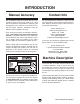
INTRODUCTION Manual Accuracy Contact Info We are proud to offer this manual with your new machine! We've made every effort to be exact with the instructions, specifications, drawings, and photographs of the machine we used when writing this manual. However, sometimes errors do happen and we apologize for them. We stand behind our machines. If you have any service questions, parts requests or general questions about the machine, please call or write us at the location listed below.
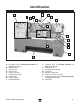
Identification A F B G D C H E J I K L M P N O Q Figure 1. Model G0554Z identification. A. Headstock (refer to Headstock Controls on Page 21 for details) B. Spindle MT#5 C. 3-Jaw Chuck D. Steady Rest E. 4-Way Tool Post F. Halogen Work Light G. Follow Rest H. Coolant Nozzle I. Compound Slide Model G0554Z (Mfg 01/09+) J. Tailstock (refer to Tailstock Controls on Page 23 for details) K. Carriage Rack L. Longitudinal Leadscrew M. Feed Rod N. Spindle Control Rod O. Coolant Tank Access Panel P.
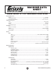
Machine Data Sheet MACHINE DATA SHEET Customer Service #: (570) 546-9663 · To Order Call: (800) 523-4777 · Fax #: (800) 438-5901 MODEL G0554Z 14" X 40" GEAR-HEAD FLOOR LATHE Product Dimensions: Weight............................................................................................................................................................ 2750 lbs. Length/Width/Height............................................................................................................................
Tailstock Info Tailstock Travel...................................................................................................................................... 4-3/4 in. Tailstock Taper.......................................................................................................................................... MT#3 Tailstock Barrel Diameter...................................................................................................................1-25/32 in.
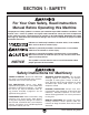
SECTION 1: SAFETY For Your Own Safety, Read Instruction Manual Before Operating this Machine The purpose of safety symbols is to attract your attention to possible hazardous conditions. This manual uses a series of symbols and signal words intended to convey the level of importance of the safety messages. The progression of symbols is described below. Remember that safety messages by themselves do not eliminate danger and are not a substitute for proper accident prevention measures.
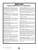
Safety Instructions for Machinery DISCONNECTING POWER SUPPLY. Always disconnect machine from power supply before servicing, adjusting, or changing cutting tools (bits, blades, cutters, etc.). Make sure switch is in OFF position before reconnecting to avoid an unexpected or unintentional start. INTENDED USE. Only use the machine for its intended purpose and only use recommended accessories. Never stand on machine, modify it for an alternative use, or outfit it with nonapproved accessories. STABLE MACHINE.
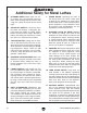
Additional Safety for Metal Lathes 1. CLEARING CHIPS. Metal chips can easily cut bare skin—even through a piece of cloth. Avoid clearing chips by hand or with a rag. Use a brush or vacuum to clear metal chips. 2. 3. CHUCK KEY SAFETY. A chuck key left in the chuck can become a dangerous projectile when the spindle is started. Always remove chuck key after using it. Develop a habit of not taking your hand off of a chuck key unless it is away from the machine. TOOL SELECTION.
SECTION 2: CIRCUIT REQUIREMENTS 220V Single-Phase Operation Serious personal injury could occur if you connect the machine to power before completing the setup process. DO NOT connect the machine to the power until instructed later in this manual. Electrocution or fire could result if machine is not grounded and installed in compliance with electrical codes.
SECTION 3: SETUP Needed for Setup This machine presents serious injury hazards to untrained users. Read through this entire manual to become familiar with the controls and operations before starting the machine! Wear safety glasses during the entire setup process! The Model G0554Z is a heavy machine. Serious personal injury may occur if safe moving methods are not used. To be safe, get assistance and use power equipment rated for at least 3500 lbs. to move the shipping crate and machine.
Inventory A B The following is a description of the main components shipped with your lathe. Lay the components out to inventory them. E Note: If you can't find an item on this list, check the mounting location on the machine or examine the packaging materials carefully. Occasionally we pre-install certain components for shipping purposes. Inventory: (Figures 3–4) Qty A. 4-jaw Chuck 8"............................................ 1 B. Faceplate 12"............................................... 1 C.
Cleanup Gasoline and petroleum products have low flash points and can explode or cause fire if used to clean machinery. Avo i d u sing t h e s e p r o d u c t s to c l e a n m a c hin e r y. The unpainted surfaces of your machine are coated with a heavy-duty rust preventative that prevents corrosion during shipment and storage. This rust preventative has been your machine's close ally and guardian since it left the factory.
Site Considerations Weight Load Physical Environment Refer to the Machine Data Sheet for the weight of your machine. Make sure that the surface upon which the machine is placed will bear the weight of the machine, additional equipment that may be installed on the machine, and the heaviest workpiece that will be used. Additionally, consider the weight of the operator and any dynamic loading that may occur when operating the machine.
Placing & Assembling Lathe 4. To balance the lifting load, loosen the tailstock lock lever, move the tailstock to the end of the bedway, then lock it in place (see Figure 8). The Model G0554Z is a heavy machine. Serious personal injury may occur if safe moving methods are not used. To be safe, get assistance and use power equipment rated for at least 3500 lbs. to move the shipping crate and machine. Tailstock Lock Lever Figure 8. Tailstock lock lever. To place and assemble your lathe: 1.
6. Attach the lifting web straps to the lifting bars and the powered lifting equipment. Note: Make sure to position the straps on the lifting bars up against the lathe to provide the best lifting safety. Also, make sure the straps will not put strain on any part of the carriage, leadscrew, or shafts. 7. Unbolt the lathe from the shipping pallet, then with an assistant to steady the load, raise the lathe a couple of inches.
Mounting to Shop Floor Checking Gear Oil You can either bolt your machine to the floor or use the included foot pads and leveling hardware. Because mounting your lathe to the floor with permanent hardware is an optional step and floor materials may vary, floor mounting hardware is not included. Whichever option you choose, it is necessary to first level your machine with a precision level to prevent cracking or warping of the cast iron bed and ways, as described on the previous page.
To test run the machine: 1. Make sure you understand the safety instructions at the beginning of the manual and that the machine is set up properly. 7. Push the emergency STOP button in, then twist it clockwise until it pops out. When the emergency stop button pops out, the switch is reset and ready for operation (see Figures 14–15). 2.
9. Verify that the machine is operating correctly by moving the spindle lever down (see Figure 13). —When operating correctly, the machine runs smoothly with little or no vibration or rubbing noises. — Investigate and correct strange or unusual noises or vibrations before operating the machine further. Always disconnect the machine from power when investigating or correcting potential problems. 10.
Spindle Break-In 8. Turn the lathe OFF and allow the spindle to come to a complete stop, then disconnect the lathe from power. NOTICE 9. Place your hand on the spindle to test its operational temperature. Successfully complete all of the spindle break-in steps to avoid rapid deterioration of the spindle bearings and components. — If the spindle is hotter than you can comfortably leave your hand on, the spindle bearing preload may need to be adjusted.
SECTION 4: OPERATIONS Operation Overview To reduce the risk of serious injury when using this machine, read and understand this entire manual before beginning any operations. Damage to your eyes and lungs could result from using this machine without proper protective gear. Always wear safety glasses and a respirator when operating this machine. This overview gives you the basic process that happens during an operation with this machine.
Basic Controls Headstock Controls A Use Figures 17–21 and the following descriptions to become familiar with the basic controls of your lathe. B Main Power Switch C B Incoming Power Terminal Box E D Figure 18. Headstock controls. Main Power Switch A. Feed Rate & Thread Charts: Show the configurations of the change gears, levers, and knobs needed to set the rotational speed of the leadscrew or feed rod. Figure 17. Main power switch. B.
Gearbox Controls Carriage Controls & Components O N M F I Y G X J H P Q W R K T L V Figure 19. Gearbox controls. F. Feed Lock Knob: Engages/disengages the power feed and the feed rate knobs. G. Numeric Feed Rate Knob: One of three controls for setting the feed rate. H. C-F Feed Rate Knob: One of three controls for setting the feed rate. I. STOP Button: When pushed, turns the spindle motor and coolant pump OFF. To reset this button, twist it clockwise until it pops out. J.
U. Apron. Houses the carriage gearing and internal components. V. Tailstock Controls Longitudinal Handwheel: Moves the carriage from side-to-side along the spindle center line in increments of 0.005" or 0.10mm. X. Saddle: Rides on top of the bedways and supports the cross slide and apron. Y. Cross Slide: Moves back-and-forth across the spindle center line and supports the compound rest. AA Z AB W. Cross Slide Handwheel: Moves the cross slide toward and away from the work.
Foot Brake The Model G0554Z lathe comes equipped with a foot brake (see Figure 22). The foot brake is intended to be used primarily as a time saving tool. The best method for using the foot brake is to turn the spindle OFF with the spindle lever, then apply even and moderate pressure to the foot brake to slow the spindle to a stop. Stepping on the foot brake while the spindle is ON will kill the power to the spindle motor and will bring the spindle to a stop.
3. One at a time, use the spindle lock key to turn the three cam-locks counterclockwise until the marks on the cam-locks align with the single marks on the spindle nose, as shown in Figure 24. As you turn the cam-locks, they will rise slightly up from the spindle nose. Marks Aligned Mounting Chuck or Faceplate 1. DISCONNECT LATHE FROM POWER! 2.
Installing Cam-Lock Studs 4. Install and tighten the locking cap screws. Tools Needed Qty Hex Wrench 5mm............................................... 1 5. To install cam-lock studs into a chuck or faceplate: 1. Lay the chuck or faceplate upside down on protective, flat surface. 2. If installed, remove the three locking cap screws adjacent to the cam-lock mounting holes (see Figure 27). Cam-Lock Stud Make sure that the cam-lock studs can rock back-and-forth against the head of the locking cap screw.
3. Clean away debris and oily substances from the mating surfaces of the jaws. 4. Flip each jaw 180°, then re-install the cap screws to secure top jaws, as shown in Figure 30. 3. Use the chuck key to open the jaws so that the workpiece lays flat against the chuck face, jaw steps, or fits into the spindle hole. See Figure 31 for examples of workpiece holding options for the 3-jaw chuck. Mounting on an Outside Diameter Figure 30. Reversing jaws. Mounting in an Inside Diameter Figure 31.
4-Jaw Chuck 5. Tighten each jaw in small increments. After you have adjusted the first jaw, continue tightening in an opposing sequence, as shown in Figure 32. Always use a low spindle speed when machining non-concentric workpieces or for off-center turning to avoid ejecting the workpiece from the mounting device at a high rate of speed. Failure to heed this warning could lead to serious personal injury, death or property damage.
Faceplate The 12" faceplate included with your lathe is used when machining non-concentric workpieces or for off-center turning by clamping the workpiece to it. Refer to the ACCESSORIES section on Page 48 for clamping options. 3. With assistance, place the workpiece onto the faceplate and clamp it in place with a minimum of three independent clamping devices (see Figure 34 for an example).
Centers Your Model G0544Z lathe includes one HSS MT#3 dead center, one carbide-tipped dead center, and one MT#5–MT#3 tapered sleeve, as shown in Figure 35. Carbide-Tipped Dead Center Live Centers Although the dead center achieves a more accurate finished product, it requires low spindle speeds to avoid heat from friction damaging the center of workpiece.
To mount a workpiece onto the spindle dead center: 1. DISCONNECT LATHE FROM POWER! 2. Thoroughly clean and dry the tapered mating surfaces of the spindle bore, tapered sleeve, and the HSS MT#3 dead center. 3. To protect these mating surfaces from rust and corrosion that could make removing them difficult, apply a thin coat of light machine oil to these surfaces, then use a c lean shop rag to wipe the surfaces again. This will leave a minimal amount of oil on the mating surfaces.
5. To prevent the workpiece slipping off the dead center tip, center drill the tailstock end of the workpiece with a tapered hole that matches the tip of the dead center. 6. Seat the center into the quill, position the tailstock so that the tip of the center presses against the workpiece enough to hold it in place, then tighten the tailstock lock lever. 7. Rotate the tailstock handwheel clockwise to feed the center farther into the workpiece until it is snug, then tighten the quill lock lever.
Tailstock Alignment The tailstock offset of your lathe was aligned with the spindle center line at the factory. We recommend that you take the time to ensure that the tailstock is aligned to your own desired tolerances, especially if you have changed the offset to cut shallow tapers. Note: As long as this dead center remains in the chuck, the point of the center will remain true to the spindle center line. The point will have to be refinished whenever the center is removed and then returned to the chuck.
Drilling with Tailstock 9. Use a caliper to measure both ends of the workpiece. — If the machined workpiece is thicker at the tailstock end, move the tailstock toward the operator 1⁄2 the distance of the amount of taper (see Figure 41). Move the tailstock toward the operator half the distance of the taper. To install an MT#3 drilling tool into the tailstock: 1. With the tailstock locked in place, unlock the quill, then use the handwheel to extend it about 1". 2.
3. Unlock the tailstock and move the tip of the bit close to, but not touching, the workpiece. 4. Start spindle rotation, unlock the quill, then turn the quill handwheel clockwise to feed the bit into the workpiece. To remove the drill chuck or drill shank, put on heavy gloves or use a shop rag to catch the tool, then rotate the quill handwheel counterclockwise until the tool is forced out of the quill.
Steady Rest The steady rest serves as a support for long shafts (length to diameter ratio of 3:1 or greater). The steady rest can be placed anywhere along the length of the bedway. 4. Loosen the star lock knob and open the steady rest so the workpiece can rest on the bottom two fingers (see Figure 47 for an example). To install/use the steady rest: 1. DISCONNECT LATHE FROM POWER! 2.
Follow Rest The follow rest in Figure 48 is mounted on the saddle and follows the movement of the tool. It can be attached/removed with the two socket head cap screws located at the base of the follow rest. The follow rest requires only two fingers as the cutting tool acts as the third. This rest is used on long, slender parts to prevent flexing of the workpiece from the pressure of the cutting tool. It should be used when the workpiece length to diameter ratio is 3:1 or greater.
Four-Way Tool Post Spindle Speed The four-way tool post is mounted on top of the compound slide, and allows a maximum of four tools to be loaded simultaneously. To set the correct spindle speed for your operation, you will need to: 1) Calculate the spindle speed (RPM) needed for your operation, and 2) configure the spindle speed levers for the calculated speed. The four-way tool post allows for quick indexing to new tools.
2. Determine the final diameter, in inches, for the cut you intend to make. 4. Note: For this step, you will need to average out the diameters or work with the finish diameter. Note: When the calculated spindle speed falls between the available speeds, use your best judgement as to which speed to use. 3.
Power Feed Understanding the Feed Rate & Threading Charts Examine the Model G0544Z feed rate and threading charts in Figure 55 on Page 41. These charts show the various configurations of the feed rate lever/knobs and the quick change gears. Power feed on the Model G0554Z uses the machine to move the tooling rather than manual rotation of the handwheels. When the feed rod is engaged, the carriage or cross slide moves.
TPI Numeric Feed Rate Knob Row 1 2 3 4 5 6 7 8 in 127 40 A 120 Change Gear Configurations 40 A 127 B 25 120 A 50 A–B Feed Rate Lever Column B C 4 41⁄2 5 51⁄2 53⁄4 6 61⁄2 7 D .0294 D .0235 .0082 .0214 .0075 .0205 .0072 .0196 .0181 .0069 .0168 .0063 .0059 9 10 11 11 ⁄2 12 13 14 1 .0147 .0131 .0051 D .0073 .0045 .0065 .0025 .0117 .0041 .0107 .0036 .0102 .0036 .0098 .0090 .0035 Longitudinal Feed Rates (Top Triangle) .0084 .0031 .0030 .0023 .0058 .0020 .0053 .
Refer to the shaded areas of the illustration in Figure 56 and the examples below to understand the layout of the top chart. 5. Set the numeric feed rate knob on the gearbox to 3, as indicated in the top row. 6. Set the quick change gears as indicated in the left column. Both 40T gears will mesh with the outer 127T gear (refer to Quick Change Gears on Page 44 for detailed instructions). TPI 1 2 3 4 5 6 7 8 in 127 40 120 A 40 A 127 25 B 120 50 A C 4 41⁄2 5 51⁄2 53⁄4 6 61⁄2 7 D .0294 .
NOTICE ALWAYS make sure the spindle is turned OFF and is at a complete stop before changing any gear configuration to prevent damage to the lathe gearing and voiding the warranty. Setting Feed Rate Controls 4. Set the feed rate lever and knobs as directed in the charts. The example illustrated in Figures 58–59 shows the setting for cutting 11 TPI threads— A, 4, and C. Note: You may need to rock the spindle, leadscrew, or feed rod back-and-forth by hand to get the gears to properly engage.
Quick Change Gears Tools Needed Qty Hex Wrench 5mm............................................... 1 Wrench or Socket 16mm.................................... 1 Wrench or Socket 18mm.................................... 1 The quick change gears are used with the feed rate controls to set the required feed rate.
6. 7. Move the middle gears up to mesh with the top gear, then tighten the hex nut to hold it in place. 2. Use the power feed direction lever to select the rotation direction of the feed rod (see the illustration in Figure 61). Note: When meshing the middle gears, make sure there is a backlash of 0.001"–0.002" between the gears. Note: The direction arrows shown above and below the power feed direction lever are only accurate when the spindle is rotating counterclockwise (toward the operator).
Threading Controls The purpose of this subsection is to orient you with the controls used when threading and how to use the threading dial. If you are unfamiliar with threading on a lathe, we strongly recommend that you read books, review industry trade magazines, or get formal training before beginning any threading projects. Thread Dial & Chart The numbers on the thread dial are used with the thread dial chart to show when to engage the half-nut during inch threading.
To use the thread dial chart (see Figure 65), find the TPI (threads per inch) on the chart that you want to cut, then reference the dial number to the right of it. The dial numbers indicate when to engage the half-nut for a specific thread pitch. Note: The thread dial chart can also be found on the front of the thread dial housing. THREAD DIAL T.P.
ACCESSORIES SECTION 5: ACCESSORIES T10096—Taper Attachment for Model G0554Z H5948—Collet Attachment for Model G0554Z H8257—Primrose Armor Plate with Moly-D Machine and Way Oil 1 Quart This superior machine and way lubricant prevents stick slip and chatter due to anti-friction capabilities resulting in greater precision machining capabilities. Provides the thinnest oil film possible while effectively providing needed lubrication and rust/corrosion protection.
G9610—Test Indicator .03" Range/.001" Resolution G9611—Test Indicator .008" Range/.0001" Resolution G9612—Test Indicator .030" Range/.0005" Resolution These test indicators have an easy to read dial and a pivoting stylus that moves at right angles to the dial face. Figure 70. Test Indicator. H6879—Lathe Operation & Maintenance Book This detailed metal lathe book provides extensive coverage of a wide variety of metalworking operations.
SECTION 6: MAINTENANCE Always disconnect power to the machine before performing maintenance. Failure to do this may result in serious personal injury. Schedule For optimum performance from your machine, follow this maintenance schedule and refer to any specific instructions given in this section. Note: This maintenance schedule is based on average daily usage. Adjust the maintenance schedule to match your usage to keep your lathe running smoothly and to protect your investment.
Lubrication Your lathe has numerous metal-to-metal moving parts that require proper lubrication to help ensure efficient and long-lasting operation. Other than the lubrication points covered in this section, all other bearings are internally lubricated and sealed at the factory. Simply leave them alone unless they need to be replaced. Figure 74. Location of the nine ball oilers on the carriage components. ALWAYS disconnect power to the lathe before performing the lubrication tasks.
NOTICE Headstock Sight Glass Drain and refill the headstock, gearbox, and apron oil reservoirs after the first 40 hours of operation to remove any sludge build-up that may accumulate from initial operation. Headstock, Gearbox, & Apron Oil Reservoirs Examine the Figures 77–80 to identify the locations of the oil sight glasses, drain plugs, and fill plugs for each oil reservoir. The reservoirs are properly filled when the oil level reaches half-way in the sight glasses.
Tensioning/ Replacing V-Belts 4. Check the deflection of the V-belts by applying moderate pressure midway between the pulleys, as illustrated in Figure 82. When properly tensioned, there should be approximately a 3⁄4" deflection. NOTICE After the first 16 hours of use, the V-belts will stretch and seat into the pulley grooves. The V-belts must be properly re-tensioned after this period to avoid severely reducing their useful life.
Replacing V-Belts Checking Coolant Tank 1. DISCONNECT LATHE FROM POWER! When checking the coolant tank, the goal is to make sure there is enough coolant, the swarf level in the first chamber of the tank is not too high, and the coolant has not become contaminated. 2. Perform Steps 2–3 of the previous procedure. 3.
3. Inspect the level and quality of the coolant. — If the level of the coolant is below approximately 2" from the top, add coolant. — Use a flashlight and inspect the level of swarf inside the first chamber of the tank. If the swarf level is beyond 3⁄4 the height of the partition wall, then the tank must be cleaned (see the illustration in Figure 84). Cleaning Coolant Tank The coolant tank of your lathe holds approximately three gallons of coolant.
SECTION 7: SERVICE Review the troubleshooting and procedures in this section to fix or adjust your machine if a problem develops. If you need replacement parts or you are unsure of your repair skills, then feel free to call our Technical Support at (570) 546-9663. Troubleshooting Motor & Gearbox Symptom Possible Cause Possible Solution Motor will not start. 1. Reset stop button. 1. Stop button not reset. 2. Turn the main power switch ON. 2. Main power switch is OFF. 3.
Operation and Work Results Symptom Possible Cause Possible Solution Bad surface finish. 1. Incorrect spindle speed or feed rate. 2. Dull tool or poor tool selection. 3. Depth of cut too great. 4. Too much play in gibs. 5. Tool too high. 1. Adjust for proper spindle speed and feed rate. 2. Use sharp tools; use correct tool for the operation. 3. Reduce depth of cut and take more passes. 4. Adjust gibs (Page 58). 5. Lower tool position. Entire machine vibrates excessively upon startup and while running.
Cross Slide Backlash Adjustment Backlash is the amount of play in a leadscrew. It is felt when turning the handwheel in one direction, then turning it in the other direction. The distance the handwheel moves without moving the leadscrew or the attached component is the backlash. When adjusting the backlash, the goal is to remove excess backlash without making the cross slide bind, making it hard to move. Overtightening will cause excessive wear on the sliding surfaces and the leadscrew.
Moving the gib toward the front of the slide increases pressure and moving it toward the rear of the slide decreases the pressure. Loosen one gib screw a small amount, tighten the other gib screw the same amount, then test the movement of the slide. Continue this process until you are satisfied with the results. Tailstock Gib The tailstock gib is adjusted in the same manner as the cross and compound slide gibs (see Figure 89).
Shear Pin Replacement The longitudinal leadscrew is secured to the connecting collar of the gearing in the headstock with the use of a soft-metal tapered shear pin (see Figure 90). The shear pin is designed to break and disengage power to the leadscrew to help protect more expensive lathe components if you crash your carriage or take too large of a cut and overload the lathe. 3. Remove the leadscrew end bracket shown in Figure 91.
Brake Pads 5. Step off the foot brake to release the brakes, then remove the pulley to expose the brake pads, as shown in Figure 93. When the brake pads are worn down to less than 1 ⁄ 8" thick, they must be replaced. If the brake pads completely wear out, then metal will grind on metal and the pulley may be ruined. When replacing the brake pads, the inside of the pulley must be turned so that it is smooth and even as the pulley also acts as the brake drum. Tools Needed Qty Phillips Screwdriver #2.........
Spindle Bearing Preload 4. Remove the chuck or faceplate from the spindle, then open the left side door to expose the outboard end of the spindle and its end cap, as shown in Figure 94. Your lathe is shipped from the factory with the preload of the spindle tapered roller bearings properly adjusted. Over time, the bearings will wear and reduce the preload, causing excessive spindle end-play, which is one cause for poor workpiece finish.
6. Remove the three cap screws that secure the spindle nut. 7. If you are performing this procedure because the normal operating temperature of the spindle was too hot, proceed with Step 8. 10. Place a dial indicator on the cross slide and move the carriage toward the spindle until the contact point of the indicator just touches the spindle face, then zero out the dial, as shown in Figure 97. If you are performing this procedure because of excessive spindle end-play, go to Step 9. 8.
13. When you are confident that you have adjusted the spindle nut so that there is no spindle end-play or preload, tighten the spindle nut an additional 9⁄16" turn clockwise to introduce the correct amount of spindle bearing preload, which is 0.003" (see Figure 98). Tip: Scribe marks on the spindle nut and the head casting to aid in turning the spindle nut 9 ⁄16". Spindle Nut 9 /16" Figure 98. Turning the spindle nut 9⁄16". 14.
SECTION 8: WIRING These pages are current at the time of printing. However, in the spirit of improvement, we may make changes to the electrical systems of future machines. Study this section carefully. If there are differences between your machine and what is shown in this section, call Technical Support at (570) 546-9663 for assistance BEFORE making any changes to the wiring on your machine. Wiring Safety Instructions 1. 2. 3. 4. SHOCK HAZARD.
Electrical Overview A Electrical Cabinet Halogen Lamp Power Junction Box Side Door Safety Switch Left Rear View C G J B Main Power Switch Control Panel D I H Spindle Switches Coolant Pump J i A Control Panel (Page 71) Brake Switch Electrical Box (Page 68) b Spindle Switches (Page 71) Halogen Lamp (Page 69) c E Side Door Safety Switch (Page 69) Brake Switch (Page 70) D G H Coolant Pump (Page 71) F -66- E F Motor READ ELECTRICAL SAFETY ON PAGE 65! Main Power Switch (Page 69)
Electrical Cabinet Identification Fuses Contactor Contactor Contactor Contactor Overload Relays Relay Transformer Grounding Plate Terminal Block Figure 100. Electrical cabinet identification.
READ ELECTRICAL SAFETY ON PAGE 65! Page 69 A PE 0 PE V12 2T1 1L1 0 PE 2 PE 11 13 U11 L PE 3L2 N 5L3 L V12 Page 70 PE U11 V12 Z11 Z11 H U21 U21 98 96 95 17.
elect components a Electrical Components (A) A Halogen Lamp To c b Electrical Cabinet (Page 68) Figure 101. Halogen lamp. C Side Door Safety Switch Side Door Safety Switch 16 6 To c b Electrical Cabinet (Page 68) NC NO C Figure 102. Side door safety switch. D Main Power Switch Main Power Switch To c b Electrical Cabinet (Page 68) PE PE To c G Power Junction Box (Page 70) L N 5 1 7 3 GND 0 1 N L 2 6 4 8 Figure 103. Main power switch.
elect components b Electrical Components (B) E Brake Switch Brake Switch NC To c b Electrical Cabinet (Page 68) NO C 3 6 Figure 104. Brake switch. To c b Electrical Cabinet (Page 68) F Motor Motor Wiring Junction Box PE U11 GND V12 W1 V1 U1 V2 U2 W2 Z12 V12 Figure 105. Motor.
elect components c Electrical Components (C) H Coolant Pump Z22 V22 GND PE Figure 107. Coolant pump. To c b U21 Electrical Cabinet (Page 68) I Spindle Switches Control Panel (viewed from rear) To c b Electrical Cabinet (Page 68) PE 8 7 NC NC 4 10 GND NO NO Spindle Switches C C FWD REV J Control Panel 3 1 GND STOP SB1 1 3 4 Figure 108. Spindle switches and control panel (viewed from the rear).
SECTION 9: PARTS Headstock Shifting Breakdown 3 2 1 3 3 3 3 17 14 5 9 15 14 17 14 8 18 13 9 8 5 7 9 8 15 10 19 18 6 14 7 16 15 4 7 M N 11 K 41 K N M 30 21 25 22 31 28 29 44 48 14 20 45 46 47 -72- 23 49 51 142 52 53 54 48 49 50 5 12 24 159 P 24 28 36 29 J 35 27 26 27 37 5 60 55 39 27 38 26 L 23 21 22 25 34 38 24 26 29 20 31 40 20 24 28 30 F 42 43 31 33 L 21 22 25 32 P J 5 20 159 56 25 25 57 58 59 56 24 F 26 27 Model G0554Z
Headstock Shifting Parts List REF PART # DESCRIPTION REF PART # DESCRIPTION 1 2 3 4 5 6 7 8 9 10 11 12 13 14 15 16 17 18 19 20 21 22 23 24 25 26 27 28 29 30 31 OIL FILL PLUG HEADSTOCK COVER CAP SCREW M6-1 X 25 GASKET O-RING 14 X 2.
Headstock Gearing Breakdown 65 66 67 73 72 64 A 75 74 68 157 88 87 86 76 63 85 82 128 62 61 84 71 70 82 81 80 97 83 79 96 78 B 95 94 93 76 92 91 77 74 82 89 106 90 128 104 109 128 74 107 105 96 69 Left Side Profile 103 102 B 99 -74- 100 108 96 S C 101 A D E Model G0554Z (Mfg 01/09+)
Headstock Gearing Parts List REF PART # DESCRIPTION REF PART # DESCRIPTION 61 62 63 64 65 66 67 68 69 70 71 72 73 74 75 76 77 78 79 80 81 82 83 84 85 86 CAP SCREW M8-1.
Headstock Spindle Breakdown 122 114 121 120 113 112 111 118 61 117 129 119 S 130 116 110 158 127 103 131 132 115 126 S 125 133 124 135 123 134 134 136 137 138 133 149 139 S 140 148 141 95 150 142 145 146 142 144 147 145 149 133 143 152 C 133 89 74 74 82 96 151 90 153 128 154 155 D 156 E -76- 128 Model G0554Z (Mfg 01/09+)
Headstock Spindle Parts List REF PART # DESCRIPTION REF PART # DESCRIPTION 61 74 82 89 90 95 96 103 110 111 112 113 114 115 116 117 118 119 120 121 122 123 124 125 126 127 128 129 CAP SCREW M8-1.25 X 16 EXT RETAINING RING 25MM BALL BEARING 6204/P5 END CAP GASKET EXT RETAINING RING 40MM BALL BEARING 6005/P5 EXT RETAINING RING 55MM CAP SCREW M6-1 X 16 END CAP GASKET CAP SCREW M5-.8 X 12 LOCK COLLAR TAP. ROLLER BEARING 32011/P5 GEAR 38T LOCK COLLAR GEAR 59T CAP SCREW M5-.8 X 20 GEAR 87T BUSHING TAP.
Gearbox Shifting Breakdown 206 207 204 202 205 203 208 210 211 209 213 233 328 329 A 201 215 B C 213 330 212 331 223 241 321 238 241 239 242 224 220 225 240 229 236 228 235 227 223 235 327 247 223 218 249 232 216 254 241 250 258 259 245 260 251 253 252 226 231 -78- 255 234 219 230 256 257 244 260 222 217 261 327 327 221 A 332 235 243 Model G0554Z (Mfg 01/09+)
Gearbox Shifting Parts List REF PART # DESCRIPTION REF PART # DESCRIPTION 201 202 203 204 205 206 207 208 209 210 211 212 213 215 216 217 218 219 220 221 222 223 224 225 226 227 228 229 230 231 232 233 CASTING PLUG GEARBOX CASTING TOP LEFT GEARBOX COVER FLAT HD SCR M4-.7 X 10 TOP RIGHT GEARBOX COVER TOP FRONT GEARBOX COVER CAP SCREW M8-1.25 X 35 CONTROL PANEL HOUSING PHLP HD SCR M3-.5 X 6 CONTROL PANEL FRONT COVER GASKET CAP SCREW M8-1.25 X 40 CAP SCREW M8-1.
Gearbox Gearing Breakdown 269 268 266 250 279 267 276 265 263 280 278 277 293 262 250 264 276 272 295 275 289 274 B 291 294 292 287 273 282 290 278 285 283 288 281 322 286 323 271 270 303 300 284 302 301 301 300 296 276 298 297 278 279 325 299 280 308 310 309 312 310 307 306 250 304 C 311 326 315 316 324 305 310 275 299 250 314 298 317 318 319 313 278 320 -80- Model G0554Z (Mfg 01/09+)
Gearbox Gearing Parts List REF PART # DESCRIPTION REF PART # DESCRIPTION 250 262 263 264 265 266 267 268 269 270 271 272 273 274 275 276 277 278 279 280 281 282 283 284 285 286 287 288 289 290 291 292 293 CAP SCREW M6-1 X 16 SPECIAL FLAT WASHER GEAR 52T CAP SCREW M6-1 X 20 END CAP GASKET BALL BEARING 6004/P5 KEY 5 X 5 X 14 GEAR SHAFT BALL BEARING 16002/P5 SHAFT COLLAR KEY 5 X 5 X 75 SHAFT SHAFT COLLAR BALL BEARING 6003/P5 EXT RETAINING RING 20MM GEAR 16T/32T BALL BEARING 6202/P5 GASKET END CAP GEAR 28T
Apron Controls 403 401 406 402 404 405 408 401 409 411 410 407 412 414 416 413 415 420 419 417 418 421 422 424 423 430 473 433 419 473 432 429 435 434 425 426 435 431 429 428 427 431 REF PART # DESCRIPTION REF PART # DESCRIPTION 401 402 403 404 405 406 407 408 409 410 411 412 413 414 415 416 417 418 CAP SCREW M6-1 X 10 HALF-NUT ASSEMBLY HALF-NUT BRACKET CAP SCREW M6-1 X 16 HALF-NUT GIB SET SCREW M6-1 X 10 CAP SCREW M8-1.25 X 40 SET SCREW M8-1.
Apron Gearing 436 439 440 438 437 441 442 444 443 E 445 447 448 446 451 449 450 452 453 454 456 455 D 462 458 457 C 459 460 461 466 474 467 463 468 464 469 465 B A B 470 C D A E 471 472 REF PART # DESCRIPTION REF PART # DESCRIPTION 436 437 438 439 440 441 442 443 444 445 446 447 448 449 450 451 452 453 454 BUSHING SHAFT EXT RETAINING RING 16MM GEAR 22T COLLAR PIN 5 X 35 GEAR 24T SET SCREW M6-1 X 6 KEY 5 X 5 X 15 SHAFT O-RING 17 X 1.
Saddle & Cross Slide Breakdown 510 508 509 511 502 507 506 515 505 513 517 512 503 514 516 502 516 501 519 527 520 523 526 525 528 521 532 524 531 531 534 Cross Slide Backlash 536 Adjustment Cap Screw 537 522 518 529 535 530 510 533 540 563 541 564 538 545 547 544 559 562 556 548 557 548 547 543 550 545 542 558 561 544 555 -84- 565 566 545 552 551 555 553 554 560 Model G0554Z (Mfg 01/09+)
Saddle & Cross Slide Parts List REF PART # DESCRIPTION REF PART # DESCRIPTION 501 502 503 505 506 507 508 509 510 511 512 513 514 515 516 517 518 519 520 521 522 523 524 525 526 527 528 529 530 531 532 CROSS SLIDE GIB GIB ADJUSTMENT SCREW PHLP HD SCR M5-.8 X 10 WIPER PLATE CROSS SLIDE BODY T-BOLT HUB BALL OILER 8MM CAP SCREW M6-1 X 20 SLEEVE SET SCREW M8-1.25 X 8 HEX NUT M10-1.
Compound Slide & Tool Post 605 602 601 604 603 606 612 608 607 609 611 613 614 616 610 617 618 637 619 620 622 623 615 634 625 626 636 638 621 632 633 635 624 628 631 634 630 627 629 REF PART # DESCRIPTION REF PART # DESCRIPTION 601 602 603 604 605 606 607 608 609 610 611 612 613 614 615 616 617 618 619 TOOL POST BASE TOOL POST LOCK SCREW HANDLE HUB HANDLE LEVER HANDLE KNOB SPACER TOOL POST STUD TOOL POST POSITION PIN COMPRESSION SPRING CLAMP BAR BALL OILER 8MM COMPOUND SLIDE CAP S
Tailstock 654 655 651 652 656 657 653 658 665 659 667 669 666 660 661 668 663 670 662 687 659 671 664 685 688 686 672 680 684 689 673 683 682 681 674 678 679 677 676 675 REF PART # DESCRIPTION REF PART # DESCRIPTION 651 652 653 654 655 656 657 658 659 660 661 662 663 664 665 666 667 668 669 670 GRADUATED DIAL CAP SCREW M6-1 X 20 BEARING HOUSING THRUST BEARING 8103 KEY 4 X 4 X 20 TAILSTOCK LEADSCREW CAP SCREW M6-1 X 16 LEADSCREW NUT HANDLE KNOB HANDLE LEVER HANDLE BOLT SPACE
Follow Rest Thread Dial 701 751 752 702 703 754 756 753 704 757 705 755 707 706 708 709 REF PART # DESCRIPTION 751 752 753 754 755 756 757 DIAL PIN 3 X 12 SHAFT PIN 3 X 20 GEAR 32T THREAD DIAL BODY CAP SCREW M6-1 X 45 P0554Z0751 P0554Z0752 P0554Z0753 P0554Z0754 P0554Z0755 P0554Z0756 PSB30M 710 REF PART # DESCRIPTION 701 702 703 704 705 706 707 708 709 710 ADJUSTMENT KNOB SET SCREW M6-1 X 6 BUSHING SPECIAL SCREW SLEEVE BRASS FINGER HEX NUT M6-1 SET SCREW M6-1 X 6 FOLLOW REST CASTING CAP SC
Steady Rest 801 803 802 804 805 806 807 808 818 810 809 819 811 812 813 814 815 816 817 REF PART # DESCRIPTION REF PART # DESCRIPTION 801 802 803 804 805 806 807 808 809 810 ADJUSTMENT KNOB SET SCREW M6-1 X 6 BUSHING ADJUSTMENT SCREW SLEEVE BRASS FINGER UPPER STEADY REST CASTING PIN 8 X 40 SET SCREW M6-1 X 20 HEX NUT M6-1 811 812 813 814 815 816 817 818 819 LOWER STEADY REST CASTING LOCK PIN HEX NUT M12-1.75 FLAT WASHER 12MM CLAMP PLATE FLAT WASHER 12MM HEX BOLT M12-1.
Change & End Gears 857 875 856 877 879 855 854 880 852 871 853 858 851 881 860 861 859 867 868 860 864 863 866 865 861 862 869 870 878 871 882 871 872 883 873 874 884 885 REF PART # DESCRIPTION REF PART # DESCRIPTION 851 852 853 854 855 856 857 858 859 860 861 862 863 864 865 866 867 GEAR 30T GEAR 40T CAP SCREW M5-.
Bed & Shaft Breakdown 953 910 905 952 907 908 909 906 911 904 916 918 917 911 921 914 924 957 955 919 920 915 923 956 927 958 954 959 960 919 922 913 912 925 928 961 926 945 929 923 930 939 941 940 931 938 932 933 936 946 942 947 951 930 929923 934 937 935 943 944 948 949 950 Model G0554Z (Mfg 01/09+) -91-
Bed & Shaft Parts List REF PART # DESCRIPTION REF PART # DESCRIPTION 904 905 906 907 908 909 910 911 912 913 914 915 916 917 918 919 920 921 922 923 924 925 926 927 928 929 930 931 932 THREADED STUD ELECTRICAL BOX GAP CAP SCREW M10-1.5 X 40 HEX NUT M8-1.25 THREADED PIN M8-1.25 BED HEX BOLT M16-2 X 50 CAP SCREW M6-1 X 25 PIN 6 X 35 LONG RACK SHORT RACK BALL OILER 10MM PLUG PLUG CAP SCREW M8-1.25 X 55 PIN 8 X 55 END BRACKET THRUST BEARING 8104 SET SCREW M8-1.
Stand & Brake Breakdown 1002 1003 1053 1001 1057 1053-5 1053-1 1058 1053-2 1053-4 1053-3 510 563 562 1053-6 1060 1059 1061 1054 1002 1055 1002 1015 1062 1004 1005 1002 1007 1017 1018 1019 1012 1013 1016 1020 1008 1011 1009 1014 1006 1010 1021 1047 1002 1052 1046 1002 1049 1045 1048 1022 1023 1024 1056 1044 1043 1042 1039 1038 1037 1026 1027 1028 1029 1036 1035 1030 1031 1034 1032 1033 1025 1040 1050 1041 1002 Model G0554Z (Mfg 01/09+) -93-
Stand & Brake Parts List REF PART # DESCRIPTION REF PART # DESCRIPTION 510 562 563 1001 1002 1003 1004 1005 1006 1007 1008 1009 1010 1011 1012 1013 1014 1015 1016 1017 1018 1019 1020 1021 1022 1023 1024 1025 1026 1027 1028 1029 1030 1031 1032 PSB02M P0554Z0562 P0554Z0563 P0554Z1001 PS68M P0554Z1003 P0554Z1004 P0554Z1005 P0554Z1006 P0554Z1007 P0554Z1008 P0554Z1009 P0554Z1010 P0554Z1011 P0554Z1012 P0554Z1013 P0554Z1014 P0554Z1015 P0554Z1016 P0554Z1017 PN13M P0554Z1019 P0554Z1020 P0554Z1021 PSS14M P0554
Electrical Breakdown 1101 1102 1103 32A 32A KA1 12 17.
Electrical Parts List REF PART # DESCRIPTION REF PART # DESCRIPTION 328 329 331 332 1052 1053 1053-1 1053-2 1053-3 1053-4 1053-5 1053-6 1054 1056 1057 1057-1 1057-2 1057-3 1057-4 1057-5 1057-6 1101 1102 1103 1104 P0554Z0328 P0554Z0329 P0554Z0331 P0554Z0332 P0554Z1052 P0554Z1053 P0554Z1053-1 P0554Z1053-2 P0554Z1053-3 P0554Z1053-4 P0554Z1053-5 P0554Z1053-6 P0554Z1054 P0554Z1056 P0554Z1057 P0554Z1057-1 P0554Z1057-2 P0554Z1057-3 P0554Z1057-4 PS55M P0554Z1057-6 P0554Z1101 P0554Z1102 P0554Z1103 P0554Z1104
Accessories 1201-1 1201-2 1202 1203 1204 1201 1205 1207 1206 1209 1208 1211 1212 1213 1214 1210 1215 1218 1219 1220 1221 1222 1223 1217 1233 961 1231 1232 1224 1230 1229 1228 1227 1225 1226 REF PART # DESCRIPTION REF PART # DESCRIPTION 961 1201 1201-1 1201-2 1202 1203 1204 1205 1206 1207 1208 1209 1210 1211 1212 1213 1214 1215 P0554Z0961 P0554Z1201 P0554Z1201-1 P0554Z1201-2 P0554Z1202 P0554Z1203 P0554Z1204 P0554Z1205 P0554Z1206 P0554Z1207 P0554Z1208 P0554Z1209 P0554Z1210 P0554Z1211
Label Placement 1251 1257 1259 1256 1255 1254 1258 1253 1252 REF PART # DESCRIPTION REF PART # DESCRIPTION 1251 1252 1253 1254 1255 LATHE CONFIGURATION LABEL MODEL NUMBER LABEL GRIZZLY OVAL NAMEPLATE ELECTRICITY LABEL MACHINE ID LABEL 1256 1257 1258 1259 ENTANGLEMENT HAZARD LABEL DISCONNECT WARNING LABEL GRIZZLY GREEN TOUCH-UP PAINT GRIZZLY PUTTY TOUCH-UP PAINT P0554Z1251 P0554Z1252 G8589 PLABEL-14 P0554Z1255 PLABEL-55 PLABEL-53 PPAINT-1 PPAINT-11 Safety labels warn about machine hazards an
WARRANTY CARD Name _____________________________________________________________________________ Street _____________________________________________________________________________ City _______________________ State _________________________ Zip _____________________ Phone # ____________________ Email ________________________ Invoice # _________________ Model # ____________________ Order # _______________________ Serial # __________________ The following information is given on a voluntary basis.
FOLD ALONG DOTTED LINE Place Stamp Here GRIZZLY INDUSTRIAL, INC. P.O.
WARRANTY AND RETURNS WARRANTY AND RETURNS Grizzly Industrial, Inc. warrants every product it sells for a period of 1 year to the original purchaser from the date of purchase. This warranty does not apply to defects due directly or indirectly to misuse, abuse, negligence, accidents, repairs or alterations or lack of maintenance.
Buy Direct and Save with Grizzly ® – Trusted, Proven and a Great Value! ~Since 1983~ Visit Our Website Today For Current Specials! ORDER 24 HOURS A DAY! 1-800-523-4777