MODEL G0442/G0601 5 HP CYCLONE DUST COLLECTOR OWNER'S Manual Copyright © APRIL, 2010 By Grizzly Industrial, Inc., Revised SEPTEMBER, 2010 (TS) Warning: No portion of this manual may be reproduced in any shape Or form without the written approval of Grizzly Industrial, inc.
This manual provides critical safety instructions on the proper setup, operation, maintenance and service of this machine/equipment. Failure to read, understand and follow the instructions given in this manual may result in serious personal injury, including amputation, electrocution or death. The owner of this machine/equipment is solely responsible for its safe use.
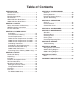
Table of Contents INTRODUCTION Manual Accuracy............................................ 2 Contact Info.................................................... 2 Machine Description....................................... 2 Identification.................................................... 3 G0442 Machine Data Sheet........................... 4 G0601 Machine Data Sheet........................... 7 SECTION 1: SAFETY Safety Instructions for Machinery.................
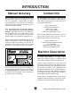
INTRODUCTION Manual Accuracy Contact Info We are proud to offer this manual with your new machine! We've made every effort to be exact with the instructions, specifications, drawings, and photographs of the machine we used when writing this manual. However, sometimes we still make an occasional mistake. We stand behind our machines. If you have any service questions, parts requests or general questions about the machine, please call or write us at the location listed below.
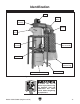
Identification Motor Outlet Hose Blower Assembly Noise Muffler Inlet Port Cyclone Assembly Canister Filter Assembly Control Box Canister Collection Bag Collection Drum w/Casters Vacuum Hose Figure 1. Identification (Model G0442 shown). To reduce the risk of serious injury when using this machine, read and understand this entire manual before beginning any operations.
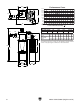
G0442 Machine Data Sheet MACHINE DATA SHEET Customer Service #: (570) 546-9663 · To Order Call: (800) 523-4777 · Fax #: (800) 438-5901 MODEL G0442 5 HP CYCLONE DUST COLLECTOR Product Dimensions: Weight.............................................................................................................................................................. 517 lbs. Length/Width/Height...............................................................................................................
Main Specifications: Operation Air Suction Cap........................................................................................................... 2184 CFM @ 1.9 in. S.P. Max Static Pressure................................................................................................................................ 14.0 in. Main Inlet Size............................................................................................................................................10 in.
G0442 Performance Curve 31¾" Performance Curve 31¾" ø8" ø8" 31¾"ø8" ø8" 57" 31¾" 57" ø8" 63" ø8" ø10" ø8" ø10" 2184 0.0 CFM 63" ø8" 2500 2250 2000 1750 1500 1250 1000 750 500 250 0 1.0 2.0 3.0 4.0 5.0 6.0 7.0 8.0 9.0 10.0 11.0 12.0 13.0 14.0 STATIC PRESSURE (Inch/H2O) 5 HP GRIZZLY DUST COLLECTOR PERFORMANCE RESULTS Max CFM Max SP HP Volts Inlet Impeller 2184 14.0 5 HP 220V 10" 16" ø8" ø8" 82¾" Restrictor plate (inch) Static pressure (Inch/H2O) CFM Dia 10" 1.9 Dia 9" 2.
G0601 Machine Data Sheet MACHINE DATA SHEET Customer Service #: (570) 546-9663 · To Order Call: (800) 523-4777 · Fax #: (800) 438-5901 MODEL G0601 5 HP 3-PHASE CYCLONE DUST COLLECTOR Product Dimensions: Weight.............................................................................................................................................................. 517 lbs. Length/Width/Height...............................................................................................................
Main Specifications: Operation Air Suction Cap............................................................................................................ 2184 CFM @1.9 in. S.P. Max Static Pressure................................................................................................................................ 14.0 in. Main Inlet Size............................................................................................................................................10 in.
G0601 Performance Curve Performance Curve 31¾" ø8" ø8" 31¾" 57" ø8" 63" ø8" 2500 2250 2000 1750 1500 1250 1000 750 500 250 0 2184 0.0 CFM 1.0 2.0 3.0 4.0 5.0 6.0 7.0 8.0 9.0 10.0 11.0 12.0 13.0 14.0 STATIC PRESSURE (Inch/H2O) 5 HP GRIZZLY DUST COLLECTOR PERFORMANCE RESULTS Max CFM Max SP HP Volts Inlet Impeller 2184 14.0 5 HP 220V 10" 16" ø10" ø8" 82¾" 46¼" 111" Restrictor plate (inch) Static pressure (Inch/H2O) CFM Dia 10" 1.9 Dia 9" 2.1 Dia. 8" 3.0 Dia. 7" 4.6 Dia.
SECTION 1: SAFETY For Your Own Safety, Read Instruction Manual Before Operating this Machine The purpose of safety symbols is to attract your attention to possible hazardous conditions. This manual uses a series of symbols and signal words intended to convey the level of importance of the safety messages. The progression of symbols is described below. Remember that safety messages by themselves do not eliminate danger and are not a substitute for proper accident prevention measures.
DISCONNECTING POWER SUPPLY.Alwaysdisconnect machine from power supply before servicing, adjusting, or changing cutting tools (bits, blades, cutters, etc.). Make sure switch is in OFF positionbeforereconnectingtoavoidanunexpectedorunintentionalstart. APPROVED OPERATION. Untrained operators can be seriously hurt by machinery. Only allow trained or properly supervised people to use machine.
Additional Safety Instructions for Dust Collectors MACHINE USE. This machine is intended to only collect wood dust and chips from woodworking machines. Do not use this dust collector as a vacuum or with machines producing dust/chips from metal, asbestos products, lead paint, silica or any products that are not natural wood or man-made wood products, such as plywood or particle boards. WEAR RESPIRATOR. This machine may blow fine dust particles into the air during operation causing a hazard to the lungs.
SECTION 2: POWER SUPPLY Availability Circuit Requirements Before installing the machine, consider the availability and proximity of the required power supply circuit. If an existing circuit does not meet the requirements for this machine, a new circuit must be installed. To minimize the risk of electrocution, fire, or equipment damage, installation work and electrical wiring must be done by a qualified electrician in accordance with all applicable codes and standards.
G0601 Circuit Requirements for 220V The Model G0601 is prewired to operate on a 220V power supply circuit that has a verified ground and meets the following requirements: Nominal Voltage............................... 220V/240V Cycle...........................................................60 Hz Phase..................................................... 3-Phase Circuit Rating....................................... 15 Amps Plug/Receptacle.............................
For Model G0601 220V operation: The recommended plug specified for the Model G0601 under Circuit Requirements has a grounding prong that must be connected to the equipmentgrounding wire of the power cord. The plug must only be inserted into a matching receptacle (outlet) that is properly installed and grounded in accordance with all local codes and ordinances (see Figure 3). GROUNDED 15-15 RECEPTACLE Extension Cords (220V Only) We do not recommend using an extension cord with this machine.
G0601 440V Conversion The Model G0601 can be converted for 440V operation. This conversion job consists of disconnecting the machine from the power source, replacing the control box assembly, and rewiring the motor for 440V operation. The necessary control box (Part P0601003-1) for this procedure can be purchased by calling Grizzly Customer Service at (800) 523-4777. All wiring changes must be inspected by a qualified electrician before the machine is connected to the power source.
Correcting Phase Polarity (G0601 Only) This subsection is only provided for troubleshooting. If you discover during the test run that the machine will not operate, or that the impeller spins backward, the power connections may be wired out-of-phase. Without the proper test equipment to determine the polarity of the power source legs, wiring machinery to 3-phase power may require trial-and-error.
SECTION 3: SETUP Needed for Setup This machine presents serious injury hazards to untrained users. Read through this entire manual to become familiar with the controls and operations before starting the machine! Wear safety glasses during the entire setup process! This machine and its components are very heavy. Get lifting help or use power lifting equipment such as a forklift to move heavy items. The following are needed to complete the setup process, but are not included with the machine.
Inventory The following is a description of the main components shipped with the machine. Lay the components out to inventory them. Collector Box Contents (Figure 7): Qty A. Intake Cylinder............................................ 1 B. Cyclone Funnel........................................... 1 C. Intake Barrel................................................ 1 D. Collection Bags — Canister Filter........................................ 2 — Collection Drum.................................... 1 E.
Stand Box Contents (Figure 8): Qty A. Lower Stand Legs....................................... 4 B. Upper Stand Legs....................................... 4 C. Upper Stand Braces.................................... 4 D. Lower Stand Braces.................................... 4 E. Collector Mounting Brackets....................... 4 F. Hardware Bags —Hex Bolts 3⁄8"-16 x 3⁄4"............................. 64 —Lock Nuts 3⁄8"-16..................................... 64 —Flat Washers 3⁄8"...........................
Hardware Recognition Chart Model G0442/G0601 (Mfg Since 8/10) -21-
Site Considerations Weight Load Physical Environment Refer to the Machine Data Sheet for the weight of your machine. Make sure that the surface upon which the machine is placed will bear the weight of the machine, additional equipment that may be installed on the machine, and the heaviest workpiece that will be used. Additionally, consider the weight of the operator and any dynamic loading that may occur when operating the machine.
Mounting to Shop Floor Although not required, we recommend that you mount this machine to the floor. Because this is an optional step and floor materials may vary, floor mounting hardware is not included. Generally, you can either bolt the machine to the floor or mount it on machine mounts. Both options are described below. Whichever option you choose, it is necessary to level the machine with a precision level.
Assembly 2. The Model G0442/G0601 is a heavy machine. Serious personal injury may occur if safe moving methods are not used. To be safe, get assistance and use power equipment to move the shipping crate and remove the machine from the crate. To assemble the dust collector: 1. Connect the upper stand legs with the lower stand braces, using (16) 3⁄8"-16 x 3⁄4" hex bolts, (32) 3⁄8" flat washers, and (16) 3⁄8"-16 lock nuts (see Figure 12).
4. Attach the cyclone funnel to the intake barrel with a barrel gasket between them, as shown in Figure 15, with (12) 5⁄16"-18 x 1" hex bolts, (24) 5⁄16" flat washers, and (12) 5⁄16"-18 hex nuts. 6. Place a large piece of cardboard on the ground to prevent scraping the parts on the bare floor during the next steps. 7. Note: At the places where you see three holes close together as shown in Figure 16, only use the center hole for this step. The two outside holes will be used in the next step.
10. Lift the assembly upright and rotate it so the inlet/outlet directions are suitable for your shop. 11. Lift the motor/blower housing assembly with a forklift and attach the intake cylinder to the bottom of the housing, as shown Figure 19, using (4) 5⁄16"-18 x 3⁄4" hex bolts and (4) 5⁄16" flat washers.
14. Attach the assembly to the intake barrel, as shown in Figure 22, with (12) 5⁄16"-18 x 3⁄4" hex bolts and (12) 5⁄16" flat washers. 16. Attach one roll of 3 x 15 x 700mm foam tape to the outside lip of each outlet port, as shown in Figure 23. 17. Attach the two filter cross braces to the L-braces, as shown in Figure 24, using (4) 3 ⁄8"-16 x 3⁄4" hex bolts, (8) 3⁄8" flat washers, and (4) 3⁄8"-16 hex nuts. x4 x 12 Figure 22. Securing blower on intake barrel. 15.
19. Using the forklift, lift the entire assembly approximately 2" off the ground to gain clearance for filter installation. 20. Mount the two filters to the braces with brace gaskets between them, as shown in Figure 26, using (8) 5⁄16"-18 x 3⁄4" hex bolts and (8) 5⁄16" fender washers. 22. Using the forklift, raise the assembly up and attach the lower stand legs to the upper stand legs, as shown in Figure 28, using (24) 3⁄8"-16 x 3⁄4" hex bolts, (48) 3⁄8" flat washers, and (24) 3 ⁄8"-16 lock nuts.
24. Connect the upper and lower collection drums together with the included metal clamp and the provided hex bolt and nut, as shown in Figure 30. 26. Install the three drum latches, as shown in Figure 32, with the (6) 10-24 x 3⁄8" Phillips head screws and (6) 10-24 hex nuts included in the box with the drum latches. Use the remaining (6) 10-24 x 3⁄8" Phillips head screws and (6) 10-24 hex nuts to plug the lower latch mounting holes.
28. Install the larger plastic collection bag into the drum, place the lid on it and hook the latch over the lid, as shown in Figure 34, then clamp it in place. 30. Fit the plastic collection bags over the bottom of the filters and clamp them in place with the metal bag clamps, as shown in Figure 36. Bag Clamp Figure 36. Canister filter collection bag installed. Figure 34. Latch hooked over the lid for clamping. 29.
32. Slide the reducer over the inlet port on the barrel (Figure 38), line up the mounting holes, and secure it in place with the (3) M4 x 12 sheet metal screws. 34. Mount the switch on the stand, as shown in Figure 40, with (2) 3⁄8"-16 x 3⁄4" hex bolts, (4) 3 ⁄8" flat washers, and (2) 3⁄8"-16 hex nuts. Reducer x3 Figure 38. Reducer installed. 33. Secure the vacuum hose inside the upper and lower stand legs with the (2) U-shaped clips (see Figure 39). Figure 40. Switch mounted to stand.
Test Run 7. Press the TIMER button on the control box and cycle through each of the times to make sure the indicators light. When the assembly is complete, test run the dust collection system to make sure it operates properly. 8. Press the TIMER button on the remote control and cycle through the times in the same manner as Step 7. If, during the test run, you cannot easily locate the source of an unusual noise or vibration, stop using the machine immediately, then review the Troubleshooting on Page 49.
SECTION 4: SYSTEM DESIGN General The Model G0442/G0601 is designed to be a central dust collector system. The large suction capacity of the Model G0442/G0601 allows great flexibility in planning and designing of the dust collection duct layout. Metal Duct Advantages of metal duct (see Figure 41) is its conductivity and that it does not contribute to static electrical charge build-up. However, static charges are still produced when dust particles strike other dust particles as they move through the duct.
Flexible Duct Flexible hose is generally used for short runs, small shops and at rigid duct-to-tool connections. There are many different types of flex hose on the market today. These are manufactured from materials such as polyethylene, PVC, cloth hose dipped in rubber and even metal, including steel and aluminum. The superior choice here is metal flex hose (see Figure 42) that is designed to be flexible, yet be as smooth as possible to reduce static pressure loss.
Designing Ducting System Your sketch only needs the basic details of the shop layout, similar to Figure 44, including all the current/planned machines and the planned placement of the dust collector. Step 1: Decide Who Will Design For most small-to-medium sized shops, you can design and build the dust collection system yourself without hiring engineers or consultants. We have included some information here to get you started on a basic design.
Step 4: Determine CFM of Each Machine BAD Figure 46. Bad duct layout. 3. Directional changes should be kept to a minimum. The more directional change fittings you use directly increases the overall resistance to airflow. 4. Gradual directional changes are more efficient than sudden directional changes (i.e. use the largest corner radius possible when changing hose or pipe direction). 5.
If the machine doesn't have a built in dust port, use Figure 48 as a guide to determine which size of dust port to install on the machine. Machine Average Dust Port Size Table Saw....................................................... 4" Miter/Radial-Arm Saw.....................................2" Jointer (6" and smaller).................................. 4" Jointer (8"-12")................................................ 5" Thickness Planer (13" and smaller)................ 4" Thickness Planer (14"-20")....
Determining Branch Line Duct Diameter The general rule of thumb for a branch line duct is that the velocity of the airflow must not fall below 4000 FPM. For small/medium sized shops, using the dust port size from the machine as the branch line duct size will achieve the correct velocity in most applications. However, if the dust port on the machine is smaller than 4", make the branch line 4" and neck the line down right before the dust port.
Calculating Duct Resistance Adding duct work, elbows, branches and any other components to a duct line increases airflow resistance (static pressure loss). This resistance can be minimized by using rigid (smooth) pipe and gradual curves, as opposed to flexible pipe and 90˚ elbows. To help you think about this resistance, imagine riding a bicycle in a tunnel that is an exact replica of the duct work.
Note: When calculating static pressure loss to determine if multiple lines can be left open at the same time, only include the main line numbers once. 5. Compare the total static pressure loss for that line to the closest CFM given in the Performance Curve section on the Machine Data Sheet for your dust collector on Page 6 (Model G0442) or Page 9 (Model G0601). Example: The Model G0601 Data Sheet Performance Curve is illustrated in Figure 56. Find 4.
System Grounding Since plastic hose is abundant, relatively inexpensive, easily assembled and air tight, it is a very popular material for conveying dust from woodworking machines to the dust collector. We recommend using flexible hose (flex-hose) to connect the woodworking machine to the dust collector. However, plastic flex-hose and plastic duct are an insulator, and dust particles moving against the walls of the plastic duct create a static electrical build up.
SECTION 5: OPERATIONS Damage to your eyes, lungs, and ears could result from using this machine without proper protective gear. Always wear safety glasses, a respirator, and hearing protection when operating this machine. Do NOT put hands or small objects near inlet openings during operation. Objects sucked into the inlet will meet with the impeller blade. Failure to heed this warning could result in property damage or personal injury.
Control Box Panel Use the illustration of the control box panel in Figure 59 and the descriptions that follow to become familiar with the functions of the buttons on the control box. A. Timer Indicator Lights: Turns ON when a timer setting is selected. B. Infrared Port: Receives infrared communication from the remote control. C. ON/OFF Button: Starts/stops the dust collector motor. D. Timer Button: Cycles through the available timer settings.
ACCESSORIES SECTION 6: ACCESSORIES H5293—4" Metal Duct Starter Kit H5295—5" Metal Duct Starter Kit H5297—6" Metal Duct Starter Kit Save over 20% with this great starter kit. Includes: (2) machine adapters, (10) pipe clamps, (3) 5' straight pipes, (1) branch, (3) pipe hangers, (1) end cap, (3) adjustable nipples, (1) 90˚ elbow, and (1) 60˚ elbow. Figure 60. Metal Duct Starter Kit.
Metal Elbows These industrial metal elbows are available from 4"–8" with 90˚, 60˚, 45˚, or 30˚ curves. Also, available with a 90˚ long radius curve. Call (800) 523-4777 or visit www.grizzly. com for more information and pricing. 90° Metal Branches We carry many different branches, all designed to minimize airflow resistance. 90° Long Radius Figure 66. Metal Branches. 30° 45° 60° Reducers & Adapters We carry a multitude of reducers and elbows to cover most applications from 4" through 9". Figure 64.
SECTION 7: MAINTENANCE Cleaning Filters Always disconnect power to the machine before performing maintenance. Failure to do this may result in serious personal injury. Schedule For optimum performance from your machine, check the following items during operation. If you notice a problem, resolve it before continuing operation. At the end of the day, make sure the machine is turned OFF and disconnected from power. During Operations: • Dust collection drums and bags. • Check/repair loose mounting bolts.
Rinsing Filter For a thorough cleaning, the filter can be removed and rinsed off. However, make sure to clean the filter with the brush system first. Allow the filter to air dry. Do not use compressed air on the pleated filter or leave it in the sun to dry—this could damage it. 3. Pull the black handle all the way down and secure the cable into the handle hook at the bottom of the canister assembly, as shown in Figure 70, to hold it in place during the following steps.
6. With help from another person to steady the canister assembly, turn it upside down and remove the two hex bolts, hex nuts, and flat washers from the cross support (see Figure 72), then remove the canister base from the assembly. 8. Before re-inserting the filter into the assembly, make sure that the filter brush base is aligned with two of the fastener holes around the base of the assembly (see Figure 74). This will allow the canister base to align with the fastener holes around the brush base.
SECTION 8: SERVICE Review the troubleshooting and procedures in this section to fix or adjust the machine if a problem develops. If you need replacement parts or you are unsure of your repair skills, then feel free to call our Technical Support at (570) 546-9663. Troubleshooting Symptom Possible Cause Possible Solution Machine does not start or a breaker trips. 1. Wall fuse/circuit breaker is blown/tripped. 1. Ensure circuit size is suitable for this machine; replace weak breaker. 2.
Symptom Possible Cause Possible Solution Loud, repetitious noise, or excessive vibration coming from dust collector. 1. Dust collector is not on a flat surface and wobbles. 2. Impeller is loose or damaged and unbalanced. 1. Stabilize the dust collector. 3. The motor mounting or housing connections are loose. 4. Impeller is loose on the motor shaft. 5. Motor fan cover is dented, causing the motor fan to hit the cover while spinning. 1. Empty collection bags. 2. Clean filters. 3.
SECTION 9: WIRING These pages are current at the time of printing. However, in the spirit of improvement, we may make changes to the electrical systems of future machines. Study this section carefully. If there are differences between your machine and what is shown in this section, call Technical Support at (570) 546-9663 for assistance BEFORE making any changes to the wiring on your machine. Wiring Safety Instructions SHOCK HAZARD.
g0442 wiring G0442 Wiring Diagram SINGLE-PHASE 220 VOLT POWER SOURCE 3L2 5L3 NO13 2T1 4T2 6T3 NO14 Contactor 1L1 GROUND A1 ON 98 97 96 OFF 95 Circuit Board Overload Relay A2 AC2 AC1 COM S IC(220V) Start Capacitor Contactor Overload Relay Circuit Board Run Capacitor -52- Figure 75. Model G0442 Figure 76. Model G0442 control box wiring. motor wiring.
g0601 wiring G0601 Wiring Diagram THREE-PHASE 220 VOLT POWER SOURCE NOTICE The Model G0601 is prewired for 220V operation. To operate your machine at 440V you must replace the 220V control box with a 440V control box—Part 0601003-1, which can be purchased separately.
Parts Breakdown SECTION 10: PARTS Main 13 12 11 G0442 1-1 1 1-4 1-2 108 1-5 1-6 8 6 7 2 17 G0601 1-1 1-2 92 Grizzly Cyclone Induction Motor 93 1-3 G0601 440V Conversion Kit 94 3-1 100 103 75 74 3 4 90 91 95 74 75 70 96 97 71 77 98 99 101 79 84 83 75 26 45 44 49 72 46 76 106 40 43 112 48 50 109 113 110 50 51 24 105 26 27-1V3 23 31 32 111 28 30 32 36AV2 29 34 35 26 30-1 33 30 105 52 36V2 54-1 88 54-2 85 67 75 26 22 89 78V2 27V3 105 25 24 39 41 42 53 1
G0442 Only Parts List REF PART # DESCRIPTION REF PART # DESCRIPTION 1 1-1 1-2 1-4 1-5 1-6 2 3 5 MOTOR 5HP 220V 1PH MOTOR FAN COVER MOTOR FAN S CAPACITOR 400M 250V 1-3/4 X 3-3/4 R CAPACITOR 40M 450V JUNCTION BOX MOTOR CORD 10G 3W CONTROL BOX ASSEMBLY 220V 1PH HEX BOLT 1/2-13 X 1-3/4 6 7 8 9 99 101 103 108 FLAT WASHER 1/2 IN LOCK WASHER 1/2 HEX NUT 1/2-13 BLOWER COVER MACHINE ID LABEL MODEL NUMBER LABEL POWER CORD 10G 3W 10' MOTOR GASKET P0442001 P0442001-1 P0442001-2 PC400C P0442001-5 P0442001-6 P044
G0442/G0601 Common Parts List REF PART # DESCRIPTION REF PART # DESCRIPTION 33 34 35 36AV2 36V2 36-1V2 36-4V2 37V2 38V2 39 40 41 42 43 44 45 46 47V2 48 49 50 51 52 53 54 54-1 54-2 55V2 56 57A 57V2 58 59 60 61 62 63 64 65 66 67 68 69 70 71 72 73 PN08 PB07 PW07 P0637041AV2 P0637041-4V2 P0637041-1V2 P0637041V2 P0637045V2 P0637046V2 P0442017 P0442040 PW07 PB07 P0442043 PB07 PW07 P0442043 P0442047V2 PB03 P0442049 PW07 PN02 P0440048 P0442053 P0440050 P0637137 P0637138 P0441051V2 P0441052 P0441053A P0440052
WARRANTY CARD Name _____________________________________________________________________________ Street _____________________________________________________________________________ City _______________________ State _________________________ Zip _____________________ Phone # ____________________ Email ________________________ Invoice # _________________ Model # ____________________ Order # _______________________ Serial # __________________ The following information is given on a voluntary basis.
FOLD ALONG DOTTED LINE Place Stamp Here GRIZZLY INDUSTRIAL, INC. P.O.
WARRANTY AND RETURNS WARRANTY AND RETURNS Grizzly Industrial, Inc. warrants every product it sells for a period of 1 year to the original purchaser from the date of purchase. This warranty does not apply to defects due directly or indirectly to misuse, abuse, negligence, accidents, repairs or alterations or lack of maintenance.
Buy Direct and Save with Grizzly ® – Trusted, Proven and a Great Value! ~Since 1983~ Visit Our Website Today For Current Specials! ORDER 24 HOURS A DAY! 1-800-523-4777