MODEL G0632 16" X 42" VARIABLE SPEED WOOD LATHE OWNER'S MANUAL COPYRIGHT © APRIL, 2007 BY GRIZZLY INDUSTRIAL, INC. WARNING: NO PORTION OF THIS MANUAL MAY BE REPRODUCED IN ANY SHAPE OR FORM WITHOUT THE WRITTEN APPROVAL OF GRIZZLY INDUSTRIAL, INC.
����������������������������������������������������������������������� �������������������������������������������������������������� ���������������������������������������������������������������������� �������������������������������������������������������������������� ������������������������ ������������������������������������������������������������������ �������������������������������������������������������������������� ����������������������������������������������������������������� ����������
Table of Contents INTRODUCTION ............................................... 2 Foreword ........................................................ 2 Contact Info ................................................... 2 Machine Data Sheet ...................................... 3 Identification ................................................... 5 SECTION 1: SAFETY ....................................... 8 Additional Safety Instructions for Wood Lathes 10 SECTION 2: CIRCUIT REQUIREMENTS ......
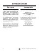
INTRODUCTION Foreword Contact Info We are proud to offer the Model G0632 16" x 42" Variable Speed Wood Lathe. This machine is part of a growing Grizzly family of fine woodworking machinery. When used according to the guidelines set forth in this manual, you can expect years of trouble-free, enjoyable operation and proof of Grizzly’s commitment to customer satisfaction.
Machine Data Sheet Machine Data Sheet ������������ ����� Customer Service #: (570) 546-9663 • To Order Call: (800) 523-4777 • Fax #: (800) 438-5901 ����������� ����������������������������������� ������������������� � � ����������������������������������������������������������������������������������������������������������������������������������������������������������������������������� ������������������������������������������������������������������������������������������������������������������
� ������������������� � � � � � � ������������������������������������������������������������������������������������������������������������������������������������������������� ���������� ���������������������������������������������������������������������������������������������������������������������������������������������������������� ���� ��������������������������������������������������������������������������������������������������������������������������������������������������������������
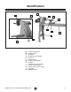
Identification C A B D E F J K L M I H G Figure 1. Model G0632 tailstock and front view. A. B. C. D. E. F. G. H. I. J. K. L. M.
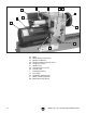
G F E D H I B C A J K M L Figure 2. Model G0632 headstock. A. B. C. D. E. F. G. H. I. J. K. L. M.
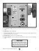
B C A D E Figure 3. Model G0632 control panel. A. Front Belt Access Panel—Remove this panel to access the drive belt and pulleys for changing speed ranges. B. RPM Readout—Shows spindle RPM. C. Emergency Stop Button—Disconnects power to the motor when pushed in. Rotate clockwise to let it pop out and reconnect power to the motor. D. REV/FWD Switch—Used to reverse the spindle direction. E. Variable Speed Dial—Varies the spindle speed from 0 RPM's to the upper limit for the selected RPM range.
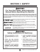
Safety ����������������� �������������������������������������� ������������������������������������ �������������������������������������������������������������������������������������������������� �������������������������������������������������������������������������������������������� �������������������������������������������������������������������������������������������� �������������������������������������������������������������������������������������������� �������������������� �����������
��������������������������������� ��� ����� ������ �������� ���� ����� ����� ����������� ���������� ��� �������� ����������� ����� ������ �������������������������������������������� ����������� ��� ��������������������������������� ����� ���� ��������� ���� ��������� �� ����� ���� ������������������������� ���� ����� ��������� ������������ ���� ���������� ������� ���������� ���� ������� ������������������ ���� ������ ������ ����� �������� ��� �������������������������������������� ������� ������ ��� �����
Additional Safety Instructions for Wood Lathes 1. KEEPING GUARDS IN PLACE. Make sure all guards are in place and the lathe sits on a flat, stable surface. 8. OPERATING DAMAGED LATHE. Never operate the lathe with damaged or worn parts. 2. EYE/FACE PROTECTION. Always wear eye protection or a face shield when operating the lathe. 9. 3. RESPIRATORY PROTECTION. Always wear a respirator when using this machine. Wood dust may cause allergies or longterm respiratory health problems. WORKPIECE CONDITION.
Circuit Requirements SECTION 2: CIRCUIT REQUIREMENTS 220V Single-Phase Plug/Receptacle Type Recommended Plug/Receptacle .......NEMA 6-15 Grounding Serious personal injury could occur if you connect the machine to the power source before you have completed the setup process. DO NOT connect the machine to the power source until instructed to do so. In the event of an electrical short, grounding reduces the risk of electric shock.
SECTION 3: SETUP Setup Safety This machine presents serious injury hazards to untrained users. Read through this entire manual to become familiar with the controls and operations before starting the machine! Wear safety glasses during the entire setup process! The G0632 and its components are very heavy. Get lifting help or use power lifting equipment such as a fork lift to move heavy items.
Inventory Inventory After all the parts have been removed from the shipping containers, you should have the following items: Inventory: (Figures 5–7) Qty A. Lathe Assembly —Headstock (mounted) ............................. 1 —Tool Rest Base (mounted)...................... 1 —Tailstock (mounted) ................................ 1 —Face Plate 6" (installed) ......................... 1 B. Supporting Legs ......................................... 2 C. Machine Feet..............................................
Hardware Recognition Chart -14- G0632 16" x 42" Variable Speed Wood Lathe
Mounting to Shop Floor Site Considerations Site Considerations Floor Load Refer to the Machine Data Sheet on Page 3 for the weight and footprint specifications of your machine. Some residential floors may require additional reinforcement to support both the machine and operator.
Clean Up Clean Up The unpainted surfaces are coated with a waxy oil to prevent corrosion during shipment. Remove this protective coating with a solvent cleaner or citrus-based degreaser such as Grizzly’s G7895 Citrus Degreaser. To clean thoroughly, some parts must be removed. For optimum performance from your machine, clean all moving parts or sliding contact surfaces. Avoid chlorine-based solvents, such as acetone or brake parts cleaner that may damage painted surfaces.
3. Secure the lathe assembly to the supporting legs with the (8) M10-1.5 x 25 cap screws and 10mm flat washers (see Figure 12). 6. Figure 12. Securing lathe assembly to supporting legs. 4. 5. If you are bolting your lathe to the floor, skip to Step 7. Otherwise, move the tailstock, tool rest assembly, and headstock to one end of the lathe bed (see the OPERATIONS section beginning on Page 18 for instructions for moving these components).
Test Run 4. Once the assembly is complete, test run your machine to make sure it runs properly and is ready for regular operation. The test run consists of verifying the following: 1) The motor powers up and runs correctly and 2) the stop button safety feature works correctly. ����� �������� ��������� If, during the test run, you cannot easily locate the source of an unusual noise or vibration, stop using the machine immediately, then review Troubleshooting on Page 36.
Operations SECTION 4: OPERATIONS Operation Safety Adjusting Headstock The Model G0632 headstock can be positioned anywhere along the lathe bed and swiveled 360°. Damage to your eyes and lungs could result from using this machine without proper protective gear. Always wear safety glasses and a respirator when operating this machine. To position the headstock along the length of the lathe bed: 1. DISCONNECT THE LATHE FROM THE POWER SOURCE! 2. Loosen the headstock lock handle (see Figure 17).
Adjusting Tailstock To swivel the headstock: 1. DISCONNECT THE LATHE FROM THE POWER SOURCE! 2. Loosen the headstock lock handle (see Figure 17). 3. Pull the swivel pin out and rotate the headstock to the desired position (see Figure 18). The tailstock is equipped with a cam-action clamping system to secure it to the lathe bed. When the lever is tightened, a locking plate lifts up underneath the bed and secures the tailstock in place. To position the tailstock along the length of the bed: 1.
Adjusting Tool Rest The tool rest base is equipped with a cam-action clamping system to secure it to the lathe bed. When the tool rest base lock handle is tightened, a locking plate lifts up and secures the tool rest assembly to the bed. The tool rest can also be positioned and locked at a specific angle or height. To position the tool rest assembly along the length of the lathe bed: 1. Always operate the lathe with the tool rest assembly firmly locked in position.
Headstock Center Installing/Removing Headstock Center 5. Make sure the center is securely installed by attempting to pull it out by hand—a properly installed center will not pull easily. To remove the headstock center with the knockout tool: Make sure the headstock and tailstock centers are properly aligned before beginning any turning operation. See Aligning Centers on Page 38 for additional instructions on this procedure.
Tailstock Center Installing/Removing Tailstock Center The included live center installs into the tailstock quill with an MT#2 tapered fit. To install the center into the tailstock quill: 1. Loosen the quill lock handle and rotate the tailstock handwheel until the quill extends out about 1" (see Figure 24). Quill Lock Handle Quill Keyway Figure 25. Quill lock handle aligned with quill keyway. Quill Lock Handle 6. Secure the quill in place by re-tightening the quill lock handle.
Headstock Faceplate Headstock Faceplate To mount a workpiece to the faceplate, refer to Faceplate Turning on Page 31. 4. Using the included 4mm hex wrench, tighten the three set screws along the inside diameter of the faceplate to secure it to the spindle (see Figure 27). The faceplate can be installed only if the headstock center has been removed. To install the headstock faceplate: 1. DISCONNECT THE LATHE FROM THE POWER SOURCE! 2.
Changing Speed Ranges Changing Speed Ranges 2. Remove the front belt access panel (see Figure 29). The Model G0632 has two speed ranges: 1) the low range from 0 to 1200 RPM which provides a greater torque, and 2) the high range from 0 to 3200 RPM. Refer to the speed recommendations chart (see Figure 28) to choose the appropriate RPM for your operation. Then choose the speed range that will include the selected RPM.
4. Use the motor tensioning handle to lift the motor assembly all the way up and re-tighten the motor mount cap screw—this will hold the motor in place while you change the belt position. 5. Reach into the belt access cavity and roll the belt onto the desired set of pulleys (see Figure 31). 7. Apply downward pressure on the motor tensioning handle to properly tension the drive belt and re-tighten the motor mount cap screw.
Indexing Indexing on a lathe is typically used for workpiece layout and other auxiliary operations that require equal distances around the workpiece circumference, such as clock faces or inlays. To use the indexing feature, place the indexing pin into one of the indexing holes in the headstock as shown in Figure 34. This will hold the spindle and workpiece at the desired indexed position.
Selecting Turning Tools • Lathe tools come in a variety of shapes and sizes, and usually fall into five major categories. • Scrapers—Typically used where access for other tools is limited, such as hollowing operations. This is a flat, double-ground tool that comes in a variety of profiles (round nose, spear point, square nose, etc.) to match many different contours. Gouges—Mainly used for rough cutting, detail cutting, and cove profiles.
Spindle Turning Spindle Turning To set up a spindle turning operation: 1. Spindle turning is the operation performed when a workpiece is mounted between the headstock and the tailstock (see Figure 39). Find the center point of both ends of your workpiece by drawing diagonal lines from corner to corner across the end of the workpiece (see Figure 40). ��������� ������������ ����������������� �������������� ��������� ������ Figure 39. Typical spindle turning operation. Figure 40.
4. To help embed the spur center into the workpiece, cut 1⁄8" deep saw kerfs in the same end of the workpiece along the diagonal lines marked in Step 1. 8. Install the live center into the tailstock quill and tighten the quill lock handle to lock the quill in position (refer to Page 22 for additional instructions). 5. If your workpiece is over 2" x 2", cut the corners off the workpiece length-wise to make turning safer and easier. 9. 6.
Tool Rest 11. Position the tool rest approximately 1⁄4" away from the workpiece and approximately 1⁄8" above the workpiece center line (see Figure 42). Spindle Turning Safety Tips: • When turning the lathe ON, stand away from the path of the spinning workpiece until the lathe reaches full speed and you can verify that the lathe will not throw the workpiece. • Use the slowest speed when starting or stopping the lathe.
Faceplate Turning Faceplate Turning Faceplate turning is when a workpiece is mounted to the faceplate, which is then mounted to the headstock spindle. This type of turning is usually done with open-faced workpieces like bowls or plates. NOTICE Only use tap screws or wood screws with non-tapered heads (Figure 45) to attach the faceplate to the workpiece. Do NOT use drywall screws or screws with tapered heads because they can split the faceplate, or the screws may snap off during operation.
Outboard Turning Sanding/Finishing Outboard turning is a variation of faceplate turning and is usually done when the stock diameter is greater than 12". For the size of this particular lathe and its minimum turning speed, we recommend a maximum diameter of 17". After the turning operations are complete, the workpiece can be sanded and finished before removing it from the lathe (see Figure 47). Figure 46 depicts the lathe setup at 90° for turning larger workpieces.
ACCESSORIES SECTION 5: ACCESSORIES G1194—3-Jaw Chuck A "must have" for the serious wood turner. This 3-jaw chuck is a self-centering style chuck used mostly for round work. All three jaws tighten together at the same time. Jaws are reversible for expanded work holding capacity.
Swan Neck H6542—Robert Sorby HSS 8-PC Turning Set If quality is king, then start bowing. Made in England, these Robert Sorby lathe tools are especially for the perfectionist wood turner. Includes 3 ⁄4" roughing gouge, 3 ⁄ 8" & 1⁄ 2" spindle gouge, 3 ⁄ 8" bowl gouge, 3 ⁄4" standard skew, 3 ⁄ 16" diamond side cut scraper, 1" square scraper and 1⁄ 2" round scraper. Full size handles are 16"–19".
SECTION 6: MAINTENANCE Lathe Bed Always disconnect power to the machine before performing maintenance. Failure to do this may result in serious personal injury. Schedule For optimum performance from your machine, follow this maintenance schedule and refer to any specific instructions given in this section. Daily Check: • Loose mounting bolts. • Damaged centers or faceplate. • Worn or damaged wires. • Any other unsafe condition. Weekly Maintenance: • Clean off dust buildup.
SECTION 7: SERVICE Troubleshooting Review the troubleshooting and procedures in this section to fix or adjust your machine if a problem develops. If you need replacement parts or you are unsure of your repair skills, then feel free to call our Technical Support at (570) 546-9663. Troubleshooting Motor & Electrical Symptom Possible Cause Machine does not 1. Emergency stop push-button is engaged/ start or a breaker faulty. trips. 2. Motor connection wired incorrectly. 3. FWD/REV switch is at fault. 4.
Wood Lathe Operation SYMPTOM POSSIBLE CAUSE CORRECTIVE ACTION Vibration noise while machine is running; noise changes when speed is changed. 1. Belt cavity cover(s) loose. 1. Tighten the screws that mount the belt cavity cover(s); if necessary install a soft, vibration dampening material between the belt cover and the headstock casting. Vibration noise while machine is running; noise remains constant when speed is changed. 1. Dented fan cover on motor. 1. Replace or adjust fan cover.
Service Log Date Approximate Hours Of Use G0632 16" x 42" Variable Speed Wood Lathe Service Performed -39-
Aligning Centers Changing V-Belt Aligning Centers Front Belt Access Panel To ensure accurate and safe turning results, the headstock and tailstock centers must be aligned with one another. To align the centers: 1. With the headstock and tailstock centers installed, slide the tailstock up to the headstock. 2. Loosen the headstock lock handle and swivel the headstock so the tip of the centers touch, as illustrated in Figure 56, then lock the headstock in place. Figure 56.
Electrical Components Electrical Components Variable Speed Control REV/FWD Switch Emergency Stop Button RPM Sensor RPM Readout & Circuit Board Figure 59. Model G0632 control panel wiring (shown from the back of the panel). Figure 61. Model G0632 RPM sensor wiring. Figure 60. Model G0632 motor junction box wiring. Figure 62. Model G0632 frequency inverter wiring.
Wiring Diagram Wiring Diagram Overview ��������� ����� �� ����� �� ����� �� ��� �� ������ �� ���� �� ����� �� (Wiring Page 41) (Figure 60, Page 39) ��������� �������� ������������� ������ � ��� �� �� �� �� �� �� �� �� �� �� �� ��� �� ��������� ���������������� �� �� �� �� ������ ������������������� ������������� ������������������������� (Figure 60, Page 39) (Figure 59, Page 39) �� �� �� �� ���������� (Figure 61, Page 39) �� �� �� �� �� �� �� �� �� �� �� �� �
Inverter Wiring Frequency Inverter Wiring Diagram ��������� ����� �� ����� �� ����� �� ��� �� ������ �� ���� �� ����� �� ������������� ������ � ��� �� �� �� ��� ����������������� ��������� �������� ���� ��� ��� �� � �� �� �� ��������� ���������������� �� �� ��� � �� �� �� �� �� �� �� �� �� �� �� �� �� �� �� �� �� �� �� �� �� �� �� �� �� �� �� �� �� �� �� �� �� ����������� ��������������������������� ���������������� �� �������� G0632 16" x 42" Variab
Stand & Bed Parts Breakdown �� �� �� �� �� �� �� �� �� �� �� �� �� �� � � � �� �� �� � � � � � �� � �� �� �� � -44- G0632 16" x 42" Variable Speed Wood Lathe
Stand & Bed Parts List REF PART # DESCRIPTION REF PART # DESCRIPTION 1 2 3 4 5 6 7 8 9 10 11 12 13 14 15 P0632001 P0632002 P0632003 P0632004 PR07M PR07M P0632007 P0632008 P0632009 P0632010 P0632011 P0632012 P0632013 P0632014 P0632015 SUPPORTING LEG BED BUSHING TOOL REST BASE LOCK BRACKET EXT RETAINING RING 18MM EXT RETAINING RING 18MM TOOL REST BASE TOOL REST TOOL REST LOCK LEVER TOOL REST BASE LOCK HANDLE LIVE CENTER QUILL TAILSTOCK LOCK BRACKET BUSHING LEAD SCREW 16 17 18 19 20 21 22 23 24 25 26
���� -46- �� �� ���� ���� ���� �� �� ���� ���� �� �� ���� �� �� ���� �� �� �� �� ���� �� �� ���� �� �� �� �� �� �� ���� �� ���� �� �� �� �� �� �� �� �� �� �� �� �� ��� �� �� �� �� �� �� ��� ��� �� �� ��� ��� �� ��� �� �� �� �� �� �� �� �� ��� �� �� �� �� ��� �� �� �� �� �� �� �� ��� �� �� �� �� �� �� Headstock Parts Breakdown G0632 16" x 42" Variable Speed Wood Lathe
Headstock Parts List REF PART # DESCRIPTION REF PART # DESCRIPTION 31 32 33 34 35 36 37 38 39 40 41 42 43 44 45 46 47 48 48-1 49 50 51 52 53 54 55 56 57 58 59 59-1 59-2 59-3 59-4 60 61 61-1 61-2 61-3 61-4 61-5 61-6 61-7 62 P0632031 PSS64M P0632033 P0632034 PK12M P6207 P6206 PR38M PR15M P0632040 P0632041 P0632042 PR07M P0632044 P0632045 PHTEK12M PSB33M P0632048 P0632048-1 P0632049 P0632050 P0632051 PS55M P0632053 P0632054 PSS80M P0632056 PS08M P0632058 P0632059 P0632059-1 PN03M P0632059-3 P0632059-4 P
Label Placement 115 118 111 114 112 113 116 110 120 119 117 REF PART # DESCRIPTION REF PART # DESCRIPTION 110 111 112 113 114 115 P0632110 P0632111 P0632112 P0632113 P0632114 P0632115 MACHINE ID LABEL READ MANUAL LABEL VERT ENTANGLEMENT LABEL HORZ EYE/LUNG LABEL HORZ BELT ACCESS LABEL CONTROL PANEL LABEL 116 117 118 119 120 PPAINT-1 PLABEL-14 P0632118 P0632119 P0632120 GRIZZLY GREEN TOUCH-UP PAINT ELECTRICITY LABEL SPINDLE ENTANGLEMENT LABEL SMALL INVERTER NOTICE LABEL LARGE INVERTER NOTIC
WARRANTY AND RETURNS Grizzly Industrial, Inc. warrants every product it sells for a period of 1 year to the original purchaser from the date of purchase. This warranty does not apply to defects due directly or indirectly to misuse, abuse, negligence, accidents, repairs or alterations or lack of maintenance.
-50- G0632 16" x 42" Variable Speed Wood Lathe
������������� ���������������������������������������������������������������������������������� � ������������������������������������������������������������������������������������ ����� ����������������������� ������������������������������� ���� ��������������������� ���������������������������� ������ ������������������������ ��������������������������� ���������������������������� ������������������������������� ��������������������������� �������������������������������������������������������������
���������������������� ����� ����� ���� ������������������������ ������������� �������������������������� ���������������������� ����������������������������������� ����������������������������������� ������������������������������������� �������������������������������������� ��������������������������������������
����������������������������������������������������������������������� ������������������������������������� ������������������������������������ ����������������� �������������������������������� ��������������������������������� ���� ��������������������� ������������������