MODEL G0644 15" OPEN-END WIDE BELT SANDER OWNER'S MANUAL COPYRIGHT © NOVEMBER, 2007 BY GRIZZLY INDUSTRIAL, INC. WARNING: NO PORTION OF THIS MANUAL MAY BE REPRODUCED IN ANY SHAPE OR FORM WITHOUT THE WRITTEN APPROVAL OF GRIZZLY INDUSTRIAL, INC.
����������������������������������������������������������������������� �������������������������������������������������������������� ���������������������������������������������������������������������� �������������������������������������������������������������������� ������������������������ ������������������������������������������������������������������ �������������������������������������������������������������������� ����������������������������������������������������������������� ����������
Table of Contents INTRODUCTION ............................................... 2 Foreword ........................................................ 2 Contact Info ................................................... 2 Machine Data Sheet ...................................... 3 Basic Identification ......................................... 5 Operation Control Identification ..................... 6 SECTION 1: SAFETY ....................................... 7 Safety Instructions for Machinery ..................
INTRODUCTION Foreword Contact Info We are proud to offer the Model G0644 15" Open-End Wide Belt Sander. The open end design of the Model G0644 can sand stock up to 30" wide. Depth of cut is precisely controlled with the elevation handwheel and scale, and the feed rate is set with the conveyor variable speed dial and monitored with the amp load meter. For quality sanding finish, the pneumatic system automatically oscillates the sanding belt from side-to-side.
Machine Data Sheet ������������� ����� ������������������������������������������������������������������������������������������ ����������� ����������������������������� ������������������� ����������������������������������������������������������������������������������������������������������������������������������������������������������������������������������� �������� ���������������������������������������������������������������������������������������������������������������������������������
������������� ��������������������������������������������������������������������������������������������������������������������������������������� ����������������������������� ����������������������������������������������������������������������������������������������������������������������������������������������������������������������� ������� ������������������������������������������������������������������������������������������������������������������������������������������������������������
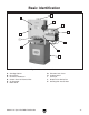
Basic Identification B A C D E K J F I G H Figure 1. Model G0644 identification. A. B. C. D. E. F. Sanding Cabinet Dust Port 4" Elevation Handwheel Control Panel & Electrical Box Air Regulator Motor 3 HP G0644 15" Open-End Wide Belt Sander G. H. I. J. K.
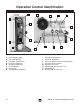
Operation Control Identification B D G F E A C H I N P L O K J M Figure 2. Model G0644 operation control identification. A. B. C. D. E. F. G. H. -6- Upper Sanding Roller Left Oscillation Disc Oscillation Control Valve Elevation Handwheel Amperage Load Chart Amp Load Meter Power Light Sanding Motor ON Button I. J. K. L. M. N. O. P.
����������������� �������������������������������������� ������������������������������������ �������������������������������������������������������������������������������������������������� �������������������������������������������������������������������������������������������� �������������������������������������������������������������������������������������������� �������������������������������������������������������������������������������������������� �������������������� �������������������
��������������������������������� ��� ����� ������ �������� ���� ����� ����� ����������� ���������� ��� �������� ����������� ����� ������ �������������������������������������������� ����������� ��� ��������������������������������� ����� ���� ��������� ���� ��������� �� ����� ���� ������������������������� ���� ����� ��������� ������������ ���� ���������� ������� ���������� ���� ������� ������������������ ���� ������ ������ ����� �������� ��� �������������������������������������� ������� ������ ��� �����
Safety Instructions for Wide Belt Sanders 1. READ THIS MANUAL. This manual contains proper operating and safety procedures for this machine. 2. KICKBACK. Kickback is typically defined as the high-speed expulsion of stock from the machine. Kickback can cause serious personal injury to the operator or bystanders. Until you have a clear understanding how kickback can occur when using this machine, DO NOT operate this sander! 3. WORKPIECE FEED RATE.
SECTION 2: CIRCUIT REQUIREMENTS 220V Operation Power Connection Device The type of plug required to connect your machine to power depends on the type of service you currently have or plan to install. We recommend using the plug shown in Figure 3. Serious personal injury could occur if you connect the machine to power before completing the setup process. DO NOT connect the machine to the power until instructed later in this manual.
SECTION 3: SETUP Setup Safety This machine presents serious injury hazards to untrained users. Read through this entire manual to become familiar with the controls and operations before starting the machine! Wear safety glasses during the entire setup process! Items Needed for Setup The following items are needed to complete the setup process, but are not included with your machine: Description Qty • Assistant ..................................................... 1 • Safety Glasses (for each person) .....
Inventory The following is a description of the main components shipped with your machine. Lay the components out to inventory them. D Note: If you can't find an item on this list, check the mounting location on the machine or examine the packaging materials carefully. Occasionally we pre-install certain components for shipping purposes. Box 1: (Figure 4) Qty A. Sanding Assembly...................................... 1 B. Sanding Belt 16" x 48" (not shown) ........... 1 C.
Hardware Recognition Chart G0644 15" Open-End Wide Belt Sander -13-
Clean Up The unpainted surfaces are coated with a waxy oil to prevent corrosion during shipment. Remove this protective coating with a solvent cleaner or citrus-based degreaser such as Grizzly’s G7895 Citrus Degreaser. To clean thoroughly, some parts must be removed. For optimum performance from your machine, clean all moving parts or sliding contact surfaces. Avoid chlorine-based solvents, such as acetone or brake parts cleaner that may damage painted surfaces.
Mounting to Shop Floor Moving & Assembling Sander The center of gravity of the assembled sander is above the middle of the machine. Although not required, we strongly recommend that you mount your new machine to the floor to prevent tipping. Because this is an optional step and floor materials may vary, floor mounting hardware is not included. The Model G0644 is a heavy machine. Serious personal injury may occur if safe moving methods are not used.
4. With an assistant to steady the sanding assembly on the forks, lift and move it into position over the cabinet stand so that the mounting holes line up (see Figures 10 & 11). 5. Secure the sanding assembly to the cabinet stand with the four hex bolts and flat washers removed in Step 2. 6. Remove the four 10-24 x 3/8" cap screws and flat washers from the front of the conveyor, slide the conveyor front roller guard onto the conveyor, and secure it with the cap screws and flat washers (see Figure 10).
8. Note: The source of compressed air must provide a steady supply of clean, dry air at 57 PSI or more, not to exceed 120 PSI. Exceeding 120 PSI may result in unpredictable operation of the sander and damage to the pneumatic system. 9. Dust Collection Connect a source of compressed air to the air regulator inlet valve on the back of the machine.
Test Run ����� Once the assembly is complete, test run your machine to make sure it runs properly and is ready for regular operation. The test run consists of verifying the following: 1) The motors power up and run correctly, 2) the EMERGENCY STOP button safety feature works correctly, and 3) the conveyor switch disabling mechanism works correctly. ��������������������� Figure 15. Resetting the EMERGENCY STOP switch. 7.
Recommended Adjustments 11. Turn the conveyor ON and verify that it operates correctly. 12. Turn the conveyor belt OFF, and remove the switch disabling key, as shown in Figure 16. For your convenience, the adjustments listed below have been performed at the factory and no further setup is required to operate your machine. However, because of the many variables involved with shipping, some of these adjustments may need to be repeated to ensure optimum results.
SECTION 4: OPERATIONS Operation Safety Sanding Overview To begin the sanding operation: Damage to your eyes, lungs, and ears could result from using this machine without proper protective gear. Always wear safety glasses, a respirator, and hearing protection when operating this machine. Loose hair and clothing could get caught in machinery and cause serious personal injury. Keep loose clothing and long hair away from moving machinery. NOTICE 1.
choosing sandpaper sanding belt replacement Choosing Sandpaper Sanding Belt Replacement Sanding Belt Size ............................ 16"W x 48"L There are many types of sanding belts to choose from. We recommend aluminum oxide for general workshop environments. Figure 17 lists groups of abrasives into different classes and shows which grits fall into each class. Grit Class Usage 36 Extra Coarse Rough sawn boards, thickness sanding, and glue removal.
4. Use the sanding belt tension lever to remove the tension on the sanding belt. 6. a. Slightly lift the tension lever, and move it to the right. b. Use moderate force to push the tension lever down, then secure it under the bottom catch, as shown in Figure 19. Slide the new sanding belt onto the upper sanding roller and sanding drum, then position it on the upper sanding roller so that it is just past the left oscillation disc, as shown in Figure 20.
depth of cut conveyor feed rate Conveyor Speed Depth of Cut The conveyor speed dial (see Figure 21) adjusts the feed rate from 5–17 FPM. The correct speed to use depends on the type of stock you are using (hardwood vs. softwood) and the stage of finish for the workpiece. Recommended maximum depth of cut .......................... Approximately 1⁄64" (0.
The amp load meter on the control panel (see Figure 23) shows how much amperage the sanding motor is drawing for the operation. When the depth of cut or conveyor feed rate becomes too great, the sanding motor will draw an excessive power load, which may trip the circuit breaker or damage the machine. Sanding Tips Follow these instructions to ensure safe sanding operation and quality results: • Replace the sandpaper with a higher grit to achieve a finer finish (refer to Choosing Sandpaper on Page 20).
• When sanding workpieces with irregular widths, take very light sanding passes to prevent gouges. As the width of the workpiece decreases, the load on the sanding motor will reduce and the sanding drum will speed up, causing a gouge. • DO NOT edge sand boards. This can cause boards to kickback, and may result in serious personal injury. Edge sanding boards also can cause damage to the conveyor belt and sandpaper.
ACCESSORIES SECTION 5: ACCESSORIES G8027—1 HP Dust Collector A great little workhorse at an incredible price! This is a great machine for sanders, router tables, shapers, and other work. It's also very portable, so you can take it to the job site. Air suction capacity: 500 CFM. G8982—Shop Fox Roller Table Use this versatile roller table wherever you need extra workpiece support. Features all steel welded construction and measures 19" x 65" long.
lubrication SECTION 6: MAINTENANCE Lubrication Always disconnect power to the machine before performing maintenance. Failure to do this may result in serious personal injury. Schedule For optimum performance from your machine, follow this maintenance schedule and refer to any specific instructions given in this section. Daily: • Check/tighten loose mounting bolts. • Check/replace damaged or worn sanding belt. • Check and repair/replace worn or damaged wires. • Check/resolve any other unsafe condition.
Air Regulator/Filter To lubricate the elevation gears: 1. 2. DISCONNECT POWER! THE SANDER FROM Use a 4mm hex wrench to loosen the set screw in the elevation handwheel hub, then remove the handwheel to access the elevation gears, as shown in Figure 30. The air regulator filters the incoming compressed air and deposits the collected water in the filter reservoir (see Figure 31). Drain Valve Filter Reservoir Figure 31. Air regulator filter reservoir and drain valve. Figure 30.
troubleshooting SECTION 7: SERVICE Review the troubleshooting and procedures in this section to fix or adjust your machine if a problem develops. If you need replacement parts or you are unsure of your repair skills, then feel free to call our Technical Support at (570) 546-9663. Troubleshooting Motor & Electrical Symptom Possible Cause Possible Solution Motor does not start 1. Compressed air to the machine is not at 57 or a breaker trips. PSI. 2. Sanding motor is not on (conveyor motor). 3.
Motor & Electrical (continued) Symptom Possible Cause Possible Solution 1. Reduce sanding depth or install coarser sandpaper. Motor stalls or is 1. Sanding depth too aggressive. overloaded. 2. Workpiece material is not suitable for this 2. Only sand wood products; make sure moisture content is below 20% and there are no foreign materials machine. in the workpiece. 3. Decrease conveyor speed (feed rate). 3. Conveyor speed too fast for task. 4. Seal all leaks, size ducts correctly, eliminate bends, 4.
tensioning & tracking Conveyor Belt Tensioning 3. Turn both of the adjustment bolts clockwise one full turn at a time until the conveyor belt no longer slips during operation. Note: Make sure the distance of the reference measurement taken in Step 1 is the same on both sides. The conveyor belt may stretch with extended use, causing it to slip on the conveyor rollers. If this happens, the conveyor belt will need to be retensioned.
gib adjustment conveyor tracking Conveyor Belt Tracking If the conveyor belt tracks to either side, the belt could become damaged and have to be replaced. Adjusting the conveyor belt tracking is a balancing process that takes patience and some trial-anderror. You must tighten the loose side adjusting bolt (the side the belt is tracking towards) to make the belt move to the middle of the rollers, then loosen that same adjusting bolt to make the conveyor stay in position.
conveyor & drum parallel Sanding Drum & Conveyor Parallelism The sanding drum and conveyor must be parallel to one another to obtain accurate sanding results. This setting is made at the factory and should not have to be made again. However, if it is necessary to adjust the sanding drum and conveyor parallel to each other, follow the procedure below. To adjust the sanding drum and conveyor parallelism: Note: Use the measurements you recorded when checking the parallelism in the previous procedure. 1.
air pressure switch depth of cut safety bar Air Pressure Safety Switch Adjusting Depth Of Cut Safety Bar The sanding motor safety brake and the sanding belt oscillation system require at least 57 PSI of air pressure connected to the machine to operate correctly. The air pressure safety switch (see Figure 36) measures the amount of air pressure flowing into the machine. If there is not adequate air pressure, the air pressure safety switch will not allow power to flow to the sander.
adjusting pressure rollers 5. 6. Place the sanded workpiece under the sanding drum and lower the sanding cabinet until the sanding drum is just touching the workpiece. Remove the workpiece from under the sanding drum and position it directly under the depth of cut safety bar. 7. Loosen the three hex bolts securing the safety bar. 8. Use feeler gauges to raise the safety bar approximately 3⁄64" (0.047") above the workpiece from side-to-side. 9. Re-tighten the hex bolts. 10.
Replacing Conveyor Belt 3. Use a 10mm wrench to loosen the conveyor adjusting jam nuts (left and right), then release the tension on the conveyor belt by loosening the tension adjusting hex bolts (see Figure 41). Contact Grizzly Customer Service at (800) 5234777 to obtain a replacement conveyor belt (Part Number P0644024). Tension Adjusting Hex Bolt To replace the conveyor belt: 1. DISCONNECT POWER! 2. Use a 4mm hex wrench to remove the M4-.
6. Use a 5mm hex wrench to remove the three M8-1.25 x 18 button head cap screws securing left rear conveyor roller bracket, leaving the rear conveyor roller assembly and bracket in place (see Figure 42). 9. With assistance, carefully lift the sanding assembly up and remove the conveyor belt, as shown in Figure 43. Note: After loosening the left conveyor roller bracket, the rear conveyor roller assembly is supported by its attachment to the conveyor motor assembly.
Electrical Wiring Overview Air Pressure Brake Solenoid (Page 40) ��� Air Pressure Safety Switch (Page 40) ��� Conveyor Motor (Page 40) ��� -38- �������������������� ���������������������� (see Page 41) Electrical Box & Control Panel (Photo: Page 39, Diagram: Page 38) 220V Power Source Sanding Motor (Page 40) G0644 15" Open-End Wide Belt Sander
electrical wiring diagram Electrical Box & Control Panel Wiring Diagram ��������� ����� ����� ��� ���� �� �� ����� �� Conveyor Motor (Page 40) �� �� �� �� Air Pressure Safety Switch (Page 40) �� �� �� �� �� �� �� �� �� �� �� �� �� �� ��� ��� ��� �� ��������� ���� ��� ��� �� ���������������� ���������������� ���� Air Pressure Brake Solenoid (Page 40) �� �� ���� ��� �� �� �� �� �� �� �� �� �� �� ���������� ������ �� �� �� �� �� �� �� ��� �� �� ��� �� ���
elect components 1 Electrical Components Conveyor DC Motor Control Contactor & Overload Relay Control Panel Figure 45. Electrical box wiring (Diagram: Page 38). Power Lamp Amp Load Meter Sanding Motor ON Button Emergency Stop Button Conveyor Speed Dial Conveyor ON/OFF Switch Figure 46. Control panel wiring (Diagram: Page 38).
elect components 2 Electrical Components ������������� �������� � �� �� �� �������������� �� � (Pages 38 & 39) Figure 47. Sanding motor wiring. ��������������� ��������� �� �� �� � ��������������� ��������� ������������� �������� � �� �������������� ��������������� ��������� � �� Figure 50. Sanding motor wiring diagram.
air system diagram Air System Diagram Air Pressure Safety Switch (Part No. 98, Page 42) 4-Way Valve (Part No. 95, Page 42) Oscillation Cylinder (Part No. 135, Page 42) Air Regulator (Part No. 92, Page 42) Oscillation Valve (Part No. 117, Page 42) Air Pressure Brake Solenoid (Part No. 99, Page 42) Sanding Motor Brake Unit (Part No.
G0644 15" Open-End Wide Belt Sander ��� �� �� ��� ��� �� ��� �� ��� ��� ��� ��� � ��� �� ��� ��� ��� ��� ��� � �� � �� ��� � ��� �� �� � �� � � �� � �� � � ��� �� ��� � �� ��� ��� ��� �� �� �� ��� ��� ��� ��� ��� ��� ��� ��� ��� ��� ��� �� �� ��� ��� ��� �� ��� � �� �� �� ��� �� ��� �� � ��� ��� ��� ��� �� � �� � ��� �� �� � �� �� �� �� �� �� � �� �� ��� �� �� � �� �� �� �� �� � � �� ��� �� �� �� �� �� ��� ��� ��� ���� �� �� ��
Parts List REF PART # DESCRIPTION REF PART # DESCRIPTION 1 2 3 4 5 6 7 8 9 10 11 12 13 13-1 14 15 16 17 18 19 20 21 22 23 24 25 26 27 28 29 30 31 32 33 34 35 36 37 38 39 40 41 42 43 44 45 46 47 48 49 CONVEYOR TABLE CONVEYOR ROLLER BRACKET LR PHLP HD SCR M8-1.
Parts List REF PART # DESCRIPTION REF PART # DESCRIPTION 93 94 95 96 97 98 99 100 101 102 103 104 105 106 107 108 109 110 111 112 113 114 115 116 117 118 119 120 121 122 123 124 125 126 TUBE CONNECTOR CONNECTING TUBE 4-WAY VALVE AIR INLET 1/4 NPT CONNECTOR AIR PRESSURE SAFETY SWITCH AIR PRESSURE BRAKE SOLENOID PHLP HD SCR 10-24 x 1-1/2 LOCK NUT 10-24 AIR PLUG SILENCER SUPPORT ARM FLAT WASHER 8MM ELEVATION ROD GUIDE LOCK WASHER 1/4 CAP SCREW 1/4-20 X 5/8 COMPRESSION SPRING THRUST BEARING 51106 LOCKING C
Label Placement & List ��� ��� ��� ��� ��� ��� ��� ��� ��� ��� ��� ��� ��� ��� ��� REF PART # DESCRIPTION REF PART # DESCRIPTION 201 202 203 204 205 206 207 MACHINE ID LABEL MODEL NUMBER LABEL ELEVATION HANDWHEEL LABEL CONTROL PANEL LABEL DISCONNECT WARNING LABEL VERT HAZARD AREA LABEL ELECTRICITY LABEL 208 209 210 211 212 213 214 GRIZZLY NAMEPLATE 9-1/4" X 4-1/2" ENTANGLEMENT HAZARD LABEL VERT EYE/LUNG HAZARD LABEL VERT READ MANUAL LABEL VERT HAND INJURY LABEL VERT GRIZZLY GREEN TOUCH UP PAI
������������� ���������������������������������������������������������������������������������� � ������������������������������������������������������������������������������������ ����� ����������������������� ������������������������������� ���� ��������������������� ���������������������������� ������ ������������������������ ��������������������������� ���������������������������� ������������������������������� ��������������������������� �������������������������������������������������������������
���������������������� ����� ����� ���� ������������������������ ������������� �������������������������� ���������������������� ����������������������������������� ����������������������������������� ������������������������������������� �������������������������������������� ��������������������������������������
WARRANTY AND RETURNS Grizzly Industrial, Inc. warrants every product it sells for a period of 1 year to the original purchaser from the date of purchase. This warranty does not apply to defects due directly or indirectly to misuse, abuse, negligence, accidents, repairs or alterations or lack of maintenance.
����������������������������������������������������������������������� ������������������������������������� ������������������������������������ ����������������� �������������������������������� ��������������������������������� ���� ��������������������� ������������������