MODEL G0679 STROKE/EDGE SANDER OWNER'S Manual Copyright © OCTOBER, 2008 By Grizzly Industrial, Inc. Warning: No portion of this manual may be reproduced in any shape Or form without the written approval of Grizzly Industrial, inc.
4HIS MANUAL PROVIDES CRITICAL SAFETY INSTRUCTIONS ON THE PROPER SETUP OPERATION MAINTENANCE AND SERVICE OF THIS MACHINE EQUIPMENT &AILURE TO READ UNDERSTAND AND FOLLOW THE INSTRUCTIONS GIVEN IN THIS MANUAL MAY RESULT IN SERIOUS PERSONAL INJURY INCLUDING AMPUTATION ELECTROCUTION OR DEATH 4HE OWNER OF THIS MACHINE EQUIPMENT IS SOLELY RESPONSIBLE FOR ITS SAFE USE 4HIS RESPONSIBILITY INCLUDES BUT IS NOT LIMITED TO PROPER INSTALLATION IN A SAFE ENVIRONMENT PERSONNEL TRAINING AND USAGE AUTHORIZATION PROPER INS
Table of Contents INTRODUCTION................................................ 2 Manual Accuracy............................................ 2 Contact Info.................................................... 2 Functional Overview....................................... 2 Identification.................................................... 3 Machine Data Sheet....................................... 4 SECTION 1: SAFETY........................................ 6 Safety Instructions for Machinery...................
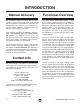
INTRODUCTION Manual Accuracy Functional Overview We are proud to offer this manual with your new machine! We've made every effort to be exact with the instructions, specifications, drawings, and photographs of the machine we used when writing this manual. However, sometimes errors do happen and we apologize for them. The Model G0679 Stroke/Edge Sander is used to sand large workpieces such as tabletops or doors.
Identification A D B E C P O N G F H M L J I K Figure 1. Identification. A. Magnetic On/Off Switch B. Belt Cover Open Latch C. Platen Press D. Platen Press Handle E. Belt Tension Handwheel F. Idler Wheel Cover G. Sanding Belt H. Table I. Adjustable Foot J. Table Handle K. Table Travel Lock L. Table Elevation Handwheel M. Work Stops N. Dust Collection Port O. Drive Wheel Cover P.
Machine Data Sheet MACHINE DATA SHEET 8jhidbZg HZgk^XZ / *,% *)+".++( Id DgYZg 8Vaa/ -%% *'("),,, ;Vm / -%% )(-"*.
Belt Information HVcY^c\ 7Zai L^Yi] ######################################################################################################################################################## + HVcY^c\ 7Zai AZc\i] ################################################################################################################################################## &-+ HVcY^c\ 7Zai HeZZY #################################################################################################################################
3%#4)/.
3AFETY )NSTRUCTIONS FOR -ACHINERY /.,9 !,,/7 42!).%$ !.$ 02/0 %2,9 350%26)3%$ 0%23/..%, 4/ /0%2!4% -!#().%29 BV`Z hjgZ deZgVi^dc ^chigjXi^dch VgZ hV[Z VcY XaZVgan jcYZghiddY# +%%0 #(),$2%. !.$ 6)3)4/23 !7!9 @ZZe Vaa X]^aYgZc VcY k^h^idgh V hV[Z Y^h" iVcXZ [gdb i]Z ldg` VgZV# -!+% 7/2+3(/0 #(),$02//& JhZ eVYadX`h! bVhiZg hl^iX]Zh! VcY gZbdkZ hiVgi hl^iX] `Znh# .%6%2 ,%!6% 7(%. -!#().% )3 25..).
Additional Safety for Stroke/Edge Sanders 1. 2. RESPIRATOR AND SAFETY GLASSES. Always wear a respirator and safety glasses while operating the machine. Dust and chips are created when sanding. Some debris will be ejected, becoming hazards to the eyes and lungs. 6. UNATTENDED OPERATION. Never leave the machine running unattended. 7. CLOTHING. DO NOT wear loose clothing while operating this machine. Roll up or button sleeves at the cuff. DUST COLLECTION SYSTEM.
SECTION 2: CIRCUIT REQUIREMENTS 220V Operation Power Connection Device The type of plug required to connect your machine to power depends on the type of service you currently have or plan to install. We recommend using the plug shown in Figure 2. Serious personal injury could occur if you connect the machine to power before completing the setup process. DO NOT connect the machine to the power until instructed later in this manual.
SECTION 3: SETUP Setup Safety This machine presents serious injury hazards to untrained users. Read through this entire manual to become familiar with the controls and operations before starting the machine! Wear safety glasses during the entire setup process! This machine and its components are very heavy. Get lifting help or use power lifting equipment such as a forklift to move heavy items.
Inventory The following is a description of the main components shipped with your machine. Lay the components out to inventory them. Note: If you can't find an item on this list, check the mounting location on the machine or examine the packaging materials carefully. Occasionally we pre-install certain components for shipping purposes. Inventory A: (Figure 3) Qty A.. Table Elevation Handwheel......................... 1 B.. Belt Tension Handwheel.............................. 1 C.. Work Stops................
Inventory D: (Figure 6) Qty A.. Table Assembly........................................... 1 B.. Idler Wheel Assembly................................. 1 A Inventory F: (Figure 8) Qty E..Platen Assembly with Motor........................ 1 F..Rear Cover.................................................. 1 G.. Cross Braces............................................... 3 H..Platen Rail Assembly.................................. 1 E F G B H Figure 6. Inventory D. Inventory E: (Figure 7) Qty C..
Hardware Recognition Chart G0679 Stroke/Edge Sander -13-
Clean Up The unpainted surfaces are coated with a waxy oil to prevent corrosion during shipment. Remove this protective coating with a solvent cleaner or degreaser, such as shown in Figure 10. For thorough cleaning, some parts must be removed. For optimum performance, clean all moving parts or sliding contact surfaces. Avoid chlorine-based solvents, such as acetone or brake parts cleaner that may damage painted surfaces. Always follow the manufacturer’s instructions when using any type of cleaning product.
Assembly After you have removed all of the components from the shipping crate and checked the inventory, assemble the machine. Items required Qty. Assistant............................................................. 1 Safety Glasses (For Each Person)..............1 Pair Square................................................................ 1 3. Attach the other upright to the two cross braces with (8) 5 ⁄ 16-18 x 1⁄ 2 flange bolts, as shown in Figure 13.
5. Connect the table elevation rod to the left and right side elevation assemblies. Place the notch in the end of the rod against the notch in the shaft at the base of the elevation assembly, slide the coupler over the joint, then tighten the set screw, as shown in Figure 15. Note: To make sure both sides are set evenly, fully lower both before connecting the table elevation rod. 7.
9. Attach the two belt cover latch assemblies to the platen assembly frame with (4) 1⁄4-20 x 1⁄ 2 flange bolts, as shown in Figure 19. 11. Secure the idler wheel box to the platen assembly with (2) 5 ⁄ 16-18 x 1⁄ 2 flange bolts and 5 ⁄ 16-18 hex nuts, as shown in Figure 21. Platen Assembly Platen Assembly Frame Belt Cover Latch Assembly Flange Bolts Idler Wheel Assembly Figure 19. Lid latches. Figure 21. Idler wheel box. 10.
13. Place the switch boom into the switch boom socket and secure with the lock knob, as shown in Figure 23. Switch Boom Lock Knob Switch Boom Socket 15. With the help of an assistant, place the table over the table rails and secure it with the (4) 5 ⁄16-18 x 3⁄4" cap screws and 5⁄16" flat washers (Figure 25). Table Cap Screw Cap Screw Figure 23. Switch boom. 14. Slide the two table rails into the table bearing assemblies on both sides of the frame (Figure 24). Table Rail Figure 25. Table mounting. 16.
17. Attach the platen press rail assembly to the left and right uprights with the (4) 1⁄4-20 x 1⁄2" cap screws, as shown in Figure 27. 19. Slide the larger handwheel on the elevation control shaft and the smaller handwheel on the belt tension shaft, then secure each by tightening the set screws and lock nuts (Figure 29). Rail Assembly Cap Screws Upright Figure 27. Platen press rail assembly. 18.
21. Attach the auxilliary workstop rods by threading the workstop rods into the machine base, then sliding the workstops over the rods and tightening the knobs. (Figure 31). Workstop Rods Machine Leveling Once assembly is complete, move your machine into position, then level it. Use a level to check from side-to-side and front-to-back. To adjust for level from side-to-side, use shims under the rear feet of the machine. To level from front-to-back, use the leveling feet.
Dust Collection Test Run Once the assembly is complete, test run your machine to make sure it runs properly. DO NOT operate the Model G0679 without an adequate dust collection system. This sander creates substantial amounts of wood dust while operating. Failure to use a dust collection system can result in short and long-term respiratory illness. To connect a dust collection hose: 1.
SECTION 4: OPERATIONS Operation Safety To reduce the risk of serious injury when using this machine, read and understand this entire manual before beginning any operations. Damage to your eyes and lungs could result from using this machine without proper protective gear. Always wear safety glasses and a respirator when operating this machine. Basic Controls Use Figures 35–36 and the descriptions below to become familiar with the basic controls of the machine. ON/OFF Switch: Turns the Motor ON/OFF.
Table Movement ON/OFF Switch: Powers the motor, turning the sanding belt. Belt Tension Handwheel: Adjusts the amount of tension that is placed on the sanding belt. Platen Press Handle: Used to exert platen pressure through the sanding belt and against the workpiece. Slides along the length of the table to allow complete sanding coverage. Table Movement Handle: Allows for easy and safe movement of the table forward and backward to provide complete sanding coverage.
Workstops Horizontal Table Movement Horizontal table movement is used together with the platen press movement to allow complete sanding of workpieces with large surface areas. Horizontal table movement can be locked when table movement is not desired. 1. Make sure the horizontal table travel locks are released by rotating them counterclockwise until the table moves freely (Figure 38). Table Handle Horizontal Table Locks Figure 38. Horizontal table movement. 2.
2. Slide the workstop up as far as it will go. It will extend approximately 3⁄8" above the surface of the table, providing a lip for the workpiece to rest against during use. 3. To lower the table workstop, loosen the flange bolts that hold the workstop to the table, lower the work stop so that it is below the surface of the table, then tighten the flange bolts to prevent them from rattling loose during use. Auxiliary Workstops 1.
7. Loosen the belt tilt lock handle and remove the two belt tilt lock knobs (Figure 42). 10. Pull the table all the way forward, lock it in place with the table travel locks, then use the table elevation handwheel to raise the table until it is even with the belt (Figure 45). Tilt Handle Table Even With Belt Lock Knob (1 of 2) Figure 42. Tilt lock handle and lock knobs. 8. Use the belt tilt handle to tilt the entire belt assembly (Figure 43). Tilt Handle Table Elevation Handwheel Figure 45.
Belt Replacement 6. Place the belt along the top platen, under the platen press, and over the other wheel, as shown in Figure 47. Replacing the sanding belt on the Model G0679 is a simple process and is performed when the sanding belt becomes worn or when a sanding belt of a different grit is desired. To replace the sanding belt: 1. DISCONNECT SANDER FROM POWER! 2. Use the belt tension handwheel to release tension from the belt. 3. Open the belt cover, drive wheel cover, and idler wheel cover (Figure 46).
Platen Press Movement A stroke sander is unique in that it uses a movable platen to apply sanding pressure to the workpiece. This allows a user to vary the amount of material removed over different areas of the workpiece. The platen press moves in two different planes. Movement in the vertical plane allows for variations in the amount of pressure applied while movement in the horizontal plane allows the user to sand different areas of the workpiece.
ACCESSORIES SECTION 5: ACCESSORIES T20501—Face Shield Crown Protector 4" T20502—Face Shield Crown Protector 7" T20503—Face Shield Window T20448—Economy Clear Safety Glasses T20452—"Kirova" Anti-Reflective Glasses T20456—"Dakura" Clear Safety Glasses H0736—Shop Fox® Safety Glasses These glasses meet ANSI Z87.1-2003 specifications. Buy extras for visitors or employees.
G5443—6" x 186"; 60 Grit G5444—6" x 186"; 80 Grit G5445—6" x 186"; 100 Grit G5446—6" x 186"; 120 Grit G5447—6" x 186"; 150 Grit G5548—6" x 186"; 180 Grit G5549—6" x 186"; 220 Grit These high quality "J" weight cloth-backed belts last longer and sand smoother! G2752—4" Rolling Floor Sweep G2753—4" Bench Dust Collection Attachment G2754—4" Floor Dust Collection Attachment These attachments are indispensable for collecting excess dust.
SECTION 6: MAINTENANCE Lubrication Always disconnect power to the machine before performing maintenance. Failure to do this may result in serious personal injury. Schedule For optimum performance from your machine, follow this maintenance schedule and refer to any specific instructions given in this section. Lubrication for the Model G0679 consists of greasing the table elevation ways, and belt tension leadscrew, oiling the table elevation chain, and refilling the table elevation gearbox.
Belt Tension Leadscrew Table Elevation Gearbox Clean the belt tension leadscrew with mineral spirits and a rag or brush to remove any grime. Dry the leadscrew, then brush on a thin coat of light multi-purpose grease. Use the belt tension handwheel to tighten and loosen the belt several times to disperse the grease (Figure 56). After every 500 hours of use, the table elevation gearbox must be refilled.
SECTION 7: SERVICE Review the troubleshooting and procedures in this section to fix or adjust your machine if a problem develops. If you need replacement parts or you are unsure of your repair skills, then feel free to call our Technical Support at (570) 546-9663. Troubleshooting Motor & Electrical Symptom Possible Cause Machine does not 1. Power supply switched OFF or is at fault. start or a breaker trips. 2. Start capacitor is at fault. 3. Motor connection wired incorrectly. 4.
Operations Symptom Possible Cause Possible Solution Machine vibrates excessively (non-motor 1. Stand not stable on floor. related). 2. Incorrect sanding belt tension. Sanded surface not square. 1. Level machine. 2. Make sure tension is correct (Page 27). 3. Broken/defective sanding belt. 3. Replace sanding belt (Page 27). 1. Table not perpendicular to belt. 1. Adjust 90° stop (Page 35). Deep sanding grooves or scores in 1. Sandpaper too coarse for the desired workpiece. finish. 2.
Table Bearings 90° Stop The table rolls forward and backwards on bearing assemblies. If you notice excessive vertical play in the table, you may need to adjust the bearing assemblies. The Model G0679 is equipped with an adjustable 90° stop to ensure that the belt is perpendicular to the table when converted to the edge sanding mode. If the belt is not 90° to the table, this stop can be adjusted. The bearings are mounted on eccentric shafts.
4. Lower the belt cover, as shown in Figure 60, to gain access to the 90° stop screws. Loosen the jam nut several turns so that the cap screw can turn freely. Belt Tracking The sanding belt tracking on the Model G0679 can be adjusted to make sure the belt travels smoothly between the drive and idler wheels without rubbing on the sides of the platen assembly. Tools Needed Qty Safety Glasses............................................1 Pair Wrench 19mm....................................................
Table Elevation Wear Pin Adjustment The table travels vertically along the table elevation ways. A series of wear pins reduce friction between the table brackets and elevation ways, making it easier to move the table up and down. Over time, these pins will wear, resulting in slop between the table brackets and elevation ways. To compensate for this wear, the wear pins can be adjusted. Tools Needed Qty Wrench 14mm.................................................... 1 3.
SECTION 8: WIRING These pages are current at the time of printing. However, in the spirit of improvement, we may make changes to the electrical systems of future machines. Study this section carefully. If there are differences between your machine and what is shown in this section, call Technical Support at (570) 546-9663 for assistance BEFORE making any changes to the wiring on your machine. Wiring Safety Instructions 1. SHOCK HAZARD.
Wiring Diagram View this page in color at www.grizzly.com. A&$& A'$( A($* CD&( ''%K c 68 '%%"'(%K 7` Dji 98 .%"&%*K Figure 63. Switch wiring. G0679 Stroke/Edge Sander WARNING! SHOCK HAZARD! Disconnect power before working on wiring. Figure 64. Motor wiring.
'* -40- )& *' (, )% '* (- (& '. )) '* (% '* ', )( )' (,"& (. )' &- &( '- + *) (' +& ), &) (+ '+ ', ( (% )+ (* )* , &+ - &' )- &+ )* &) & () '& '+ (+ &+ &. )."& )."( )."' ''+ ' . ''+ '' (* ') &+ ') )."* ).") &, () &* *. '& +% '( '% '' ''+ ). . ') '' ') '& '% && . ) '( *.
Main Parts List REF PART # DESCRIPTION REF PART # DESCRIPTION 1 2 3 4 5 6 7 8 9 10 11 12 13 14 15 16 17 18 19 20 21 22 23 24 25 26 27 28 29 30 31 32 BELT PLATE ASSEMBLY FRONT BELT PLATE ASSEMBLY GEAR BOX ASSEMBLY TABLE ASSEMBLY RIGHT UPRIGHT ASSEMBLY LEFT UPRIGHT ASSEMBLY PLATEN ASSEMBLY PLATEN PRESS ASSEMBLY CONNECTING TUBE PHLP HD SCR 10-24 X 3/8 SANDING BELT 100 GRIT PLATEN ASSEMBLY ROD COUNTERWEIGHT FLANGE BOLT 1/4-20 X 1/2 FLANGE BOLT 5/16-18 X 1/2 FLAT WASHER 1/2 HANDWHEEL COVER CHAIN CONNECTING
Belt & Idler Wheel Assembly Breakdown &'' &&% &%( &') &&& &'( &&% &', &&- &%( &%. &'* &%( &&+ &&* &&, &'* &'+ &%' &%* &&& &%. &%' &'- &%' &&' &'& &'. &&. &%& &%* &&) &'. &&( &'% &%+ &%, &%- ''( ''* '%' '&' '&) '%) '%* '&( '%+ '%, '&+ ''+ ''% '') '%( '%( '&- '&* '%* '%( '%) '%'%. '%'&% '&& ''' ''& '&, '%& '&.
Belt Assembly Parts List REF PART # DESCRIPTION REF PART # DESCRIPTION 101 102 103 105 106 107 108 109 110 111 112 113 114 115 116 117 118 119 120 121 122 123 124 125 126 127 128 BAR CLAMP (SMALL) HOOK (SMALL) BALL HANDLE FLANGE WASHER CAP SCREW M6-1 X 20 KEY 7 X 7 X 75 HEX NUT 3/8-16 HOOK (BIG) CAP SCREW 3/8-16 X 1-1/4 CONNECTOR 1/2-12 X 1-3/4 HEX BOLT 5/16-18 X 1 DRIVING WHEEL LEFT COVER BOARD BELT PLATE DRIVING WHEEL COVER PHLP HD SCR 5/16-18 X 1/2 LOCK NUT 1/2-12 MOTOR 3HP 220V 1-PH FLANGE BOLT 5/1
Gearbox & Table Breakdown & Parts List (%& (%. (%& (&% (%( (%) (%( (%) (%* (%* (%.
Right Upright Assembly Breakdown *)& *&& *&' *%) *'& *&% *&' *&& *&( *%+ *&) *%) *'' *), *%) *%) *%- *'+ *%) *%* *', *%, *'- *', *%. *&* *'* *'* *%) *%* *)& *'. *&+ *'+ *&, *'. *&*&. *&' *'' *'( *'*%, *&) *)( *&, *)) *(& *(' *(( *(' *)( *(' *() *)( *(' *() *(( *(' *)( *)' *)( *)- *(, *(- *)% *&& *), *)* *)+ *%' *') *%' *%( *(% *)( *(( *(' *'% *&' *&& *%& *%& *)) *%' *%' *(* *(+ *(.
Right Upright Assembly Parts List REF PART # DESCRIPTION REF PART # DESCRIPTION 501 502 504 505 506 507 508 509 510 511 512 513 514 515 516 517 518 519 520 521 522 523 524 525 CHAIN COVER CAP SCREW 1/4-20 X 3/8 PHLP HD SCR 1/4-20 X 3/8 L-PLATE HEX BOLT 5/16-18 X 1/2 HEX BOLT 5/16-18 X 1 CAP SCREW 5/16-18 X 1/2 COVER RIGHT SUPPORT FOOT BALL BEARING 6240ZZ INT RETAINING RING 47MM CHAIN WHEEL ADAPTER SPROCKET CHAIN COVER DUST COVER CAP SCREW 5/16-18 X 3/4 GEAR BAR (RIGHT) GEAR BAR (LEFT) CAP SCREW 5/16-18
G0679 Stroke/Edge Sander +)% +(& +(& +(& +'' +', +*) +*, +*. +*+*, ++% +*) +*) +** +%, +%+ +%* +&. +'% +'& +%. +&+&& +%( +%- +*) +*) +*, +*. +*+*, +*) ++& +*( +** +*+ +*, +*+*, +%. +), +%) +&) +&* +') +*% +'* +&% +&) +*% +)- +)) +%) +%' +(& +*% +*& +'+ +'- +(% +(& +(( +() +(' +*' +(% +%( +%* +%& +&( +') +'* +). +(, +'+'. +'+ +'* +') +(* +(+ +(, +(- +)) +)* +(& +)& +(& +)( +(- +(& +)& +(& +&+ +&, +)) +)( +)' +). +*% +*& +)+ +(.
Left Upright Assembly Parts List REF PART # DESCRIPTION REF PART # DESCRIPTION 601 602 603 604 605 606 607 608 609 610 611 613 614 615 616 617 618 619 620 621 622 624 625 626 627 628 629 630 631 632 HEX NUT 1/2"-12 FOOT PAD SPECIAL PIN SQUARE CAP CAP GEAR BOX CAP SCREW M8-1.25 X 80 HANDWHEEL SPINDLE COPPER TUBE HANDWHEEL ASSEMBLY CAP SCREW 3/8-16 X 3/4 GEAR BOX SPINDLE SET SCREW 5/16-18 X 1/2 HANDWHEEL HEX NUT 3/8"-16 INDICATOR LOCK WASHER 3/8 HEX NUT M8-1.25 ADJUSTABLE BAR HEX BOLT M5-.
Platen Press Assembly Breakdown & Parts List ,&% ,%& ,&& ,&' ,%.
Labels Breakdown & Parts List 903 902 909 904 905 909 902 901 901 908 907 906 910 910 REF PART # DESCRIPTION REF PART # DESCRIPTION 901 902 903 904 905 DISCONNECT POWER LABEL VS BELT DIRECTION LABEL ELECTRICITY LABEL 0.
7!22!.
;DA9 6ADC< 9DII:9 A>C: EaVXZ HiVbe =ZgZ '2)::,9 ).$5342)!, ).# 0 / "/8 "%,,).
WARRANTY AND RETURNS 7!22!.49 !.$ 2%452.
"UY $IRECT AND 3AVE WITH 'RIZZLY® n 4RUSTED 0ROVEN AND A 'REAT 6ALUE 6ISIT /UR 7EBSITE 4ODAY !ND $ISCOVER 7HY 'RIZZLY® )S 4HE )NDUSTRY ,EADER s 3%#52% /2$%2).' s /2$%23 3()00%$ 7)4(). (/523 s % -!), 2%30/.3% 7)4(). /.