MODEL G0689 13" PLANER WITH BUILT-IN DUST COLLECTION OWNER'S Manual Copyright © SEPTEMBER, 2008 By Grizzly Industrial, Inc. Warning: No portion of this manual may be reproduced in any shape Or form without the written approval of Grizzly Industrial, inc.
4HIS MANUAL PROVIDES CRITICAL SAFETY INSTRUCTIONS ON THE PROPER SETUP OPERATION MAINTENANCE AND SERVICE OF THIS MACHINE EQUIPMENT &AILURE TO READ UNDERSTAND AND FOLLOW THE INSTRUCTIONS GIVEN IN THIS MANUAL MAY RESULT IN SERIOUS PERSONAL INJURY INCLUDING AMPUTATION ELECTROCUTION OR DEATH 4HE OWNER OF THIS MACHINE EQUIPMENT IS SOLELY RESPONSIBLE FOR ITS SAFE USE 4HIS RESPONSIBILITY INCLUDES BUT IS NOT LIMITED TO PROPER INSTALLATION IN A SAFE ENVIRONMENT PERSONNEL TRAINING AND USAGE AUTHORIZATION PROPER INS
Table of Contents INTRODUCTION................................................ 2 Manual Accuracy............................................ 2 Contact Info.................................................... 2 Functional Overview....................................... 2 Identification.................................................... 3 SECTION 1: SAFETY........................................ 6 Safety Instructions for Machinery................... 6 Additional Safety Instructions for Planers.......
INTRODUCTION Manual Accuracy Functional Overview We are proud to offer this manual with your new machine! We've made every effort to be exact with the instructions, specifications, drawings, and photographs of the machine we used when writing this manual. However, sometimes errors do happen and we apologize for them. The Model G0689 Planer allows the user to plane material from the surface of boards in precise increments.
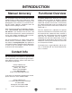
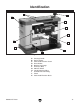
Identification B C A D E F K G J H I Figure 1. Identification. A. Carrying Handle B. Return Rollers C. Cutterhead Elevation Crank D. Reset Button E. Depth-of-cut Gauge F. Thickness Stop G. ON/OFF Switch H. Infeed Extension Wing I. Outfeed Extension Wing J. Platen K.
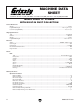
MACHINE DATA SHEET 8jhidbZg HZgk^XZ / *,% *)+".++( Id DgYZg 8Vaa/ -%% *'("),,, ;Vm / -%% )(-"*.
Cutterhead Info 8jiiZg]ZVY IneZ ########################################################################################################################################## HigV^\]i @c^[Z 8jiiZg]ZVY 9^V# ############################################################################################################################################################# ' Cd# d[ @c^kZh #######################################################################################################################################
3%#4)/.
3AFETY )NSTRUCTIONS FOR -ACHINERY /.,9 !,,/7 42!).%$ !.$ 02/0 %2,9 350%26)3%$ 0%23/..%, 4/ /0%2!4% -!#().%29 BV`Z hjgZ deZgVi^dc ^chigjXi^dch VgZ hV[Z VcY XaZVgan jcYZghiddY# +%%0 #(),$2%. !.$ 6)3)4/23 !7!9 @ZZe Vaa X]^aYgZc VcY k^h^idgh V hV[Z Y^h" iVcXZ [gdb i]Z ldg` VgZV# -!+% 7/2+3(/0 #(),$02//& JhZ eVYadX`h! bVhiZg hl^iX]Zh! VcY gZbdkZ hiVgi hl^iX] `Znh# .%6%2 ,%!6% 7(%. -!#().% )3 25..).
Additional Safety Instructions for Planers 1. Instruction manual. This machine presents significant safety hazards to untrained users. Read/understand this entire manual before starting the planer. 2. REACHING INSIDE PLANER. Never reach inside planer or remove cover when the planer is connected to power. 3. Infeed clearance Safety. The infeed roller is designed to pull material into the cutterhead.
SECTION 2: CIRCUIT REQUIREMENTS 110V Operation Serious personal injury could occur if you connect the machine to power before completing the setup process. DO NOT connect the machine to the power until instructed later in this manual. Power Connection Device The Model G0689 comes with a 5-15 plug, similar to Figure 2, to connect the machine to power.
SECTION 3: SETUP Setup Safety This machine presents serious injury hazards to untrained users. Read through this entire manual to become familiar with the controls and operations before starting the machine! Inventory The following is a description of the main components shipped with your machine. Lay the components out to inventory them. Items: (Figure 3) Qty A.. Planer (Not Shown)..................................... 1 B.. Magnets....................................................... 2 C..
Clean Up The unpainted surfaces are coated with a waxy oil to prevent corrosion during shipment. Remove this protective coating with a solvent cleaner or degreaser, such as shown in Figure 4. For thorough cleaning, some parts must be removed. For optimum performance, clean all moving parts or sliding contact surfaces. Avoid chlorine-based solvents, such as acetone or brake parts cleaner that may damage painted surfaces. Always follow the manufacturer’s instructions when using any type of cleaning product.
Assembly To attach the elevation crank assembly: 1. Align the flat portion inside the crank bore with the flat portion on the shaft, then place the crank assembly on the elevation shaft. 2. Thread the M6-1 x 20 button head screw with the flat washer through the crank and into the shaft to secure the crank in place, as shown in Figure 6. DO NOT over-tighten. Screw & Washer Test Run Once the assembly is complete, test run your machine to make sure it runs properly and is ready for regular operation.
5. Turn the machine OFF. 6. Remove the switch disabling key, as shown in Figure 8. Mounting Once you have confirmed that your machine is running properly, you may choose to mount it to a workbench through the holes in the base. The strongest mounting option is a "Through Mount" where holes are drilled all the way through the workbench, and hex bolts, washers, and hex nuts are used to secure the planer to the workbench. Figure 8. Removing switch key from paddle switch. 7.
SECTION 4: OPERATIONS Operation Safety Basic Controls Use the descriptions and figures below to become familiar with the basic controls of your machine. Damage to your eyes, lungs, and ears could result from using this machine without proper protective gear. Always wear safety glasses, a respirator, and hearing protection when operating this machine. Cutterhead Elevation Scale: Displays the elevation the cutterhead is above the platen.
Elevation Crank: Controls the elevation of the cutterhead. Elevation Lock: Locks the vertical position of the cutterhead to prevent unwanted movement during use. Thickness Stop: Limits downward travel of the cutterhead at specific distances from the platen to easily plane workpieces to specific thicknesses. ON/OFF Switch The ON/OFF switch is located on the front of the planer. The switch has a disabling key that, when removed, allows it to be locked in the OFF position.
Depth-of-Cut The planing depth is controlled by the cutterhead elevation crank on top of the planer. Turning the crank clockwise raises the cutterhead and turning it counterclockwise lowers the cutterhead. The Model G0689 has multiple methods for determining the depth-of-cut depending on your planing needs. The elevation crank, cutterhead elevation scale, thickness stop, and depth-of-cut gauge all provide a means for accurately measuring the material that will be removed from wood workpieces.
Thickness Stop The thickness stop stops the cutterhead assembly at pre-set workpiece thicknesses. Use the thickness stop to plane to any of the following thicknesses: 1⁄8", 1⁄4", 1⁄2", 3⁄4", 1", and 1 1⁄4". Cutterhead Elevation Indicator To use the thickness stop: 1. Rotate the thickness stop knob to the desired setting (Figure 16). Cutterhead Elevation Scale Figure 17. Depth-of-cut scale and indicator.
Basic Operations To use the planer: 1. Put on safety glasses. 2. If your workpiece is bowed, surface plane the workpiece on a jointer until one side is flat— doing so will ensure that it sits solidly on the planer table during operation. 3. Place the workpiece onto the infeed extension wing with the flat side down, so that the front edge of the workpiece is just under the cutterhead assembly enough to set the depth of cut, and set the depth-of-cut, using the Depth-of-Cut Gauge (Page 16).
Wood Characteristics Below is a list of wood characteristics you may encounter when planing. The following descriptions of defects will give you some possible answers to problems you may encounter while planing different materials. Possible solutions follow the descriptions. Chipped Grain Problem: Usually a result of cutting against the grain, planing lumber with knots or excessive amount of cross grain, or using dull knives. Solution: Decrease the depth-of-cut.
Wood Types Similarly, common softwood shear strengths are displayed in Figure 20. The species of wood, as well as its condition, has a dramatic effect on the depth-of-cut the planer can effectively take with each pass. A greater shear strength indicates a harder wood. A shallower cut should be used with harder woods.
ACCESSORIES SECTION 5: ACCESSORIES T20803—13" Replacement Knives Set of two reversible replacement knives for the Model G0689 13" Planer. T20501—Face Shield, 4" Crown, Clear T20502—Face Shield, 7" Crown, Clear T20448—Economy Clear Safety Glasses T20452—"Kirova" Anti-Relective Glasses T20456—"Dakura" Clear Safety Glasses H0736—Shop Fox® Safety Glasses These glasses meet ANSI Z87.1-2003 specifications. Buy extras for visitors or employees.
T20514—Small Half-Mask Respirator T20515—Medium Half-Mask Respirator T20516—Large Half-Mask Respirator T20511—Pre-Filter P100 T20539—Cartridge Filter 2PK P100 T20541—Cartridge Filter 2PK P100 & O Vapor Wood and other types of dust can cause severe respiratory damage. If you work around dust everyday, a half-mask respirator can greatly reduce your risk.
SECTION 6: MAINTENANCE Lubrication Always disconnect power to the machine before performing maintenance. Failure to do this may result in serious personal injury. Schedule For optimum performance from your machine, follow this maintenance schedule: There are four primary points that require periodic lubrication—the head elevation screws, the elevation lock cams, the columns, and the feed roller chain drive. Access for lubrication requires removing the top and side covers of the machine first (Figure 28).
SECTION 7: SERVICE Review the troubleshooting and procedures in this section to fix or adjust your machine if a problem develops. If you need replacement parts or you are unsure of your repair skills, then feel free to call our Technical Support at (570) 546-9663. Troubleshooting Symptom Possible Cause Possible Solution Motor will not run. 1. No power to planer. 2. Motor overload protection tripped. 1. Check power supply. 2. Turn planer OFF. Reset overload protection (Page 15). 3.
Knife Replacement Knife Guard The cutterhead knives on the Model G0689 are extremely sharp. Brushing your finger along the edge can result in a severe cut. Take extreme caution when doing any of the adjustments involving the cutterhead knives. Wear heavy leather gloves anytime it is necessary to manually rotate the cutterhead assembly. Cap Screws Figure 29. Removing knife guard (top and side covers removed for clarity). 3.
4. Remove the six button head cap screws from the gib. 5. Use the included magnets, as shown in Figure 31, to first remove the gib, then the knife. Magnets Before re-installing the knives, the cutterhead, gib and knife must be inspected. Neglecting to inspect these components may result in damage to the planer. To inspect the cutterhead, gib, and knives: 1. DISCONNECT PLANER FROM POWER! 2.
Motor To install the knives: 1. DISCONNECT PLANER FROM POWER! 2. Using the magnets, position the knife over the two pins on the cutterhead. Be sure the knife is oriented with the beveled edge up, as shown in Figure 32. Beveled Edge Up Keep the motor as clean as possible. Prevent any water, oil, or wood chips from penetrating inside the motor. Be sure to clean the machine after every use.
Drive Belt The cutterhead is driven by a belt that is located on the right-hand side of the motor and cutterhead assembly (when facing the front of the machine). The belt is very durable, but with extended use may begin to slip, indicating the need for replacement. Tools Needed Qty Hex Wrench 4mm............................................... 1 Hex Wrench 5mm............................................... 1 Hex Wrench 6mm............................................... 1 To replace the belt: 1.
Impeller Belt Feed Rollers The dust collection system on the Model G0689 is powered by a belt-driven impeller. The belt is very durable, but with extended use it may begin to slip, resulting in a reduction in dust collection performance. The feed rollers rotate in bushing blocks that are spring loaded. The feed rollers ride up on the board so that the roller pressure is maintained.
6. Raise the cutterhead assembly and remove the block of wood. 7. Repeat Steps 1–4 for the other feed roller. 8. Replace the sides, top plates, and elevation crank. Extension Wing/ Table Alignment Your planer is equipped with front and rear extension wings. Each wing folds up for machine mobility and folds down for machine operation. To check the alignment, lay a straightedge across the table and both wings (see Figure 40).
4. Loosen the lock nuts, then turn each adjustment bolt so that it just touches the cam when the lock lever is approximately halfway through its travel, then tighten the lock nuts. Note: It is important that all four adjustment bolts are set equally. Failure to do this could cause the cutterhead to move during use, resulting in inconsistent planing. Thickness Stop Calibration 4. Locate the thickness stop bolt and lock nut. Manually rotate the thickness stop to the position shown in Figure 42.
Wiring Diagram View this page in color at www.grizzly.com. CZjigVa COLOR KEY =di 110 VAC 5-15 Plug I: Li I8= DK:GAD69 HL>I8= k^ZlZY [gdb WZ]^cY k^ZlZY [gdb WZ]^cY Figure 43. Switch wiring.
SECTION 8: PARTS Main Parts Breakdown + , & ' ) . &% &* && &+ &' ''. (% (& (' &( &- &, &. '% '& +( +) +% +& +* ++ +, +- +' ,& ,' ,) &&' &&% +. ,% ,( ,* ,+ &&& ,, '+ '' '( ') &) '* -( -) -* -+ -% -& -, -' ,. -- (( ', )' () (* (+ (, (-. .% .& .' (. .( .) )& .* .+ )( ()% )) *% )* )+ ), )+ )). ** *+ *& *' *( *) ,*, *&&* &'&&) *. &&( &'. .. ., .&%. &%% &%, &%&%( &%* &&. &'% &%' &'+ &', &)& &(% &&+ &(& &(, &)( &%+ &'& &&, &(* &)' &(&%* &%) &&&)) &%& &(.
Main Parts List REF PART # DESCRIPTION REF PART # DESCRIPTION 1 2 3 4 5 6 7 8 9 10 11 12 13 14 15 16 17 18 19 20 21 22 23 24 25 26 27 28 29 30 31 32 33 34 35 36 37 BUTTON HD CAP SCR M6-1 X 20 FLAT WASHER 6MM SIDE COVER (RH) HANDLE STEP KNOB HANDLE CAP HANDLE BOLT HANDLE BASE PLUG UPPER COVER CLEVIS PIN BUSHING ROLLER PLUG BUTTON HD CAP SCR M8-1.25 X 16 GRIP TAP SCREW M4 X 6 AIR GUIDE CAP SCREW M5-.8 X 10 DUST GUARD TAP SCREW M4 X 10 CAP SCREW M5-.8 X 10 DUST CHUTE CAP SCREW M5-.
Main Parts List (Continued) REF PART # DESCRIPTION REF PART # DESCRIPTION 75 76 77 78 79 80 81 82 83 84 85 86 87 88 89 90 91 92 93 94 95 96 97 98 99 100 101 102 103 104 105 106 107 108 109 110 111 112 GEAR (LARGE) 70T BRACKET STANDOFF INSIDE COVER PINION GEAR BALL BEARING 6202ZZ GEAR (SMALL) 52T X 12T BUSHING SPACER UNDERCUT SPECIAL NUT M14 SET SCREW M6-1 X 6 ELEVATING NUT (LH) CAP SCREW M5-.8 X 10 SET PLATE CAP SCREW M5-.8 X 14 BUTTON HD CAP SCR M5-.8 X 10 CABLE CLAMP CAP SCREW M5-.
Base Parts Breakdown &+' &+( &*& &*. &+) &+% &+& &*( &+* &++ &*' &*) &** &*& &*' &*( &+, &*+ &*, &*- &,& &,&.. '%% &,' &,("& &,. &-% &,) &-& &-' &-( &-) &-* &-+ &-, &-- -36- '%' '%( &,, &,+ '%) '%* &,* &., &.- '%& '%+ '%, ( * &.% &.& &-. &.' &.( &.) &.* &.
Base Parts List REF PART # DESCRIPTION REF PART # DESCRIPTION 151 152 153 154 155 156 157 158 159 160 161 162 163 164 165 166 167 171 172 173-1 174 175 176 177 178 179 180 COMPRESSION SPRING ROLLER COMPRESSION SPRING (INFEED) EXT RETAINING RING 15MM SPROCKET BEARING BLOCK RETAINER CAP SCREW M5-.8 X 10 SIDE COVER (LH) TAP SCREW M5 X 25 CORD SPOOL HEX WRENCH 4MM MAGNET PLATEN GUIDE CAP SCREW M5-.8 X 10 COLUMN ELEVATING SCREW BASE SPECIAL NUT HEX BOLT M6-1 X 20 HEX NUT M6-1 FLAT HD SCR M4-.
Warning Labels Breakdown and List 302 303 301 304 307 306 305 308 309 REF PART # DESCRIPTION REF PART # DESCRIPTION 301 302 303 304 305 HEARING PROTECTION LABEL VS MACHINE ID LABEL GLASSES/RESPIRATOR LABEL VS MODEL NUMBER LABEL ELECTRICITY LABEL 0.
7!22!.
;DA9 6ADC< 9DII:9 A>C: EaVXZ HiVbe =ZgZ '2)::,9 ).$5342)!, ).# 0 / "/8 "%,,).
WARRANTY AND RETURNS 7!22!.49 !.$ 2%452.
"UY $IRECT AND 3AVE WITH 'RIZZLY® n 4RUSTED 0ROVEN AND A 'REAT 6ALUE 6ISIT /UR 7EBSITE 4ODAY !ND $ISCOVER 7HY 'RIZZLY® )S 4HE )NDUSTRY ,EADER s 3%#52% /2$%2).' s /2$%23 3()00%$ 7)4(). (/523 s % -!), 2%30/.3% 7)4(). /.