MODEL G0695 VS MILLING MACHINE WITH RAM HEAD OWNER'S Manual Copyright © JULY, 2009 By Grizzly Industrial, Inc., REVISED OCTOBER, 2010 (TS) Warning: No portion of this manual may be reproduced in any shape Or form without the written approval of Grizzly Industrial, inc.
This manual provides critical safety instructions on the proper setup, operation, maintenance and service of this machine/equipment. Failure to read, understand and follow the instructions given in this manual may result in serious personal injury, including amputation, electrocution or death. The owner of this machine/equipment is solely responsible for its safe use.
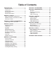
Table of Contents INTRODUCTION................................................ 2 Manual Accuracy............................................ 2 Contact Info.................................................... 2 Machine Description....................................... 2 Identification.................................................... 3 Machine Data Sheet....................................... 4 SECTION 1: SAFETY........................................ 6 Safety Instructions for Machinery...................
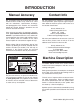
INTRODUCTION Manual Accuracy Contact Info We are proud to offer this manual with your new machine! We've made every effort to be exact with the instructions, specifications, drawings, and photographs of the machine we used when writing this manual. However, sometimes we still make an occasional mistake. We stand behind our machines. If you have any service questions, parts requests or general questions about the machine, please call or write us at the location listed below.
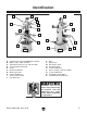
Identification B A E C D S F M G N R O L P H Q I K Front Rear J Figure 1. Model G0695 identification. A. Control Panel (refer to Page 19 for details) B. Motor 1 1⁄2 HP, 220V, 3-Phase C. V-Belt Belt Tension Lever and Lock Bolt D. Coarse Downfeed Handle E. Turret F. Downfeed Selector G. Work Light 110V H. X-Axis Handwheel I. Z-Axis Crank Handle J. One-Shot Oiler K. Base L. Splash Pan M. Belt Access Plate N. Headstock Ram O. X-Axis Handwheel P. Cross (Y-Axis) Feed Limit Stops Q.
Machine Data Sheet MACHINE DATA SHEET Customer Service #: (570) 546-9663 · To Order Call: (800) 523-4777 · Fax #: (800) 438-5901 MODEL G0695 VS MILLING MACHINE WITH RAM HEAD Product Dimensions: Weight............................................................................................................................................................ 1070 lbs. Length/Width/Height.................................................................................................................
Table Info Table Length.............................................................................................................................................. 30 in. Table Width.................................................................................................................................................. 8 in. Table Thickness........................................................................................................................................... 2 in. No.
SECTION 1: SAFETY For Your Own Safety, Read Instruction Manual Before Operating this Machine The purpose of safety symbols is to attract your attention to possible hazardous conditions. This manual uses a series of symbols and signal words intended to convey the level of importance of the safety messages. The progression of symbols is described below. Remember that safety messages by themselves do not eliminate danger and are not a substitute for proper accident prevention measures.
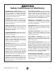
Safety Instructions for Machinery DISCONNECTING POWER SUPPLY. Always disconnect machine from power supply before servicing, adjusting, or changing cutting tools (bits, blades, cutters, etc.). Make sure switch is in OFF position before reconnecting to avoid an unexpected or unintentional start. INTENDED USE. Only use the machine for its intended purpose and only use recommended accessories. Never stand on machine, modify it for an alternative use, or outfit it with nonapproved accessories. STABLE MACHINE.
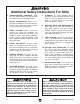
Additional Safety Instructions For Mills 1. UNDERSTANDING CONTROLS. Make sure you understand the use and operation of all controls before operating machine. 2. Safety accessories. Always use a chip guard in addition to your safety glasses, or use a face shield when milling to reduce the risk of injury from flying chips. 3. 4. 5. 6. WORK HOLDING. Before starting the machine, be certain the workpiece has been properly clamped to the table.
Glossary of Terms The following is a list of common definitions, terms and phrases used throughout this manual as they relate to this mill and metalworking in general. Become familiar with these terms for assembling, adjusting and operating this mill. Your safety is VERY important to us at Grizzly! Arbor: A tapered shaft that holds a cutting tool. Collet: A tapered shaped split-sleeve bushing that holds round tools by their outside diameter.
SECTION 2: CIRCUIT REQUIREMENTS 220V Single-Phase Operation Power Connection Device The type of plug required to connect your machine to power depends on the type of service you currently have or plan to install. We recommend using the plug shown in Figure 2. Serious personal injury could occur if you connect the machine to power before completing the setup process. DO NOT connect the machine to the power until instructed later in this manual.
SECTION 3: SETUP Needed for Setup This machine presents serious injury hazards to untrained users. Read through this entire manual to become familiar with the controls and operations before starting the machine! Wear safety glasses during the entire setup process! The Model G0695 is a heavy machine. Serious personal injury may occur if safe moving methods are not used. To be safe, get assistance and use power equipment to move the shipping crate and remove the machine from the pallet.
Inventory The following is a description of the main components shipped with your machine. Lay the components out to inventory them. Note: If you can't find an item on this list, check the mounting location on the machine or examine the packaging materials carefully. Occasionally we pre-install certain components for shipping purposes. If any nonproprietary parts are missing (e.g.
Cleanup Gasoline and petroleum products have low flash points and can explode or cause fire if used to clean machinery. Avo i d u sing t h e s e p r o d u c t s to c l e a n m a c hin e r y. The unpainted surfaces of your machine are coated with a heavy-duty rust preventative that prevents corrosion during shipment and storage. This rust preventative has been your machine's close ally and guardian since it left the factory.
Site Considerations Weight Load Physical Environment Refer to the Machine Data Sheet for the weight of your machine. Make sure that the surface upon which the machine is placed will bear the weight of the machine, additional equipment that may be installed on the machine, and the heaviest workpiece that will be used. Additionally, consider the weight of the operator and any dynamic loading that may occur when operating the machine.
Moving & Placing Mill The Model G0695 is a heavy machine. Serious personal injury may occur if safe moving methods are not used. To be safe, get assistance and use power equipment to move the shipping crate and remove the machine from the crate. To move and place your mill: 1. After removing the crate sides from the shipping pallet, adjust the headstock and table as close to the mill body as possible, and install the lifting straps as shown in Figure 6. 2.
Assembly Bolting to Concrete Floors Anchor studs and lag shield anchors with lag bolts (see Figure 7) are two popular methods for anchoring an object to a concrete floor. We suggest you research the many options and methods for mounting your machine and choose the best that fits your specific application. To assemble your mill: 1. Secure the three handles to the handwheels with the M6-1 x 25 cap screws, as shown in Figure 9. Handle Anchor Stud Lag Shield Anchor & Bolt Figure 7.
Test Run Once the assembly is complete, test run your machine to make sure it runs properly and is ready for regular operation. The test run consists of verifying the following: 1) The motor powers up and runs correctly and 2) the stop button safety feature works correctly. 6. Push the stop button in, then twist it clockwise so it pops out. When the stop button pops out, the switch is reset and ready for operation (see Figure 11).
Spindle Break-In It is essential to closely follow the proper break-in procedures to ensure trouble-free performance of your mill. NOTICE DO NOT leave the area while the breakin procedure is under way. You must be ready to stop the machine if any problem occurs. NOTICE Successfully complete the spindle break-in procedure to avoid rapid wear of spindle components when placed into operation. -18- To perform the spindle break-in procedure: 1.
SECTION 4: OPERATIONS Basic Controls To reduce the risk of serious injury when using this machine, read and understand this entire manual before beginning any operations. Refer to Figure 12 and the following descriptions to understand the basic controls of your mill. Control Panel A B C Damage to your eyes or face could result from using this machine without proper protective gear. Always wear safety glasses or a face shield when operating this machine. F E D Figure 12. Control panel.
Table Controls Refer to Figures 13–14 and the following descriptions to understand the functions that affect X-, Y-, and Z-axis table movement. F. Y-Axis Lock: Locks the saddle, preventing the table from moving in the Y-axis. G. Y-Axis Limit Stops: Limit Y-axis table travel. A. X-Axis Handwheels: Controls left-right (X-axis) travel of the table. H. Z-Axis Crank Handle: Controls up-down (Z-axis) travel of the table. B. X-Axis Limit Stops: Limits X-axis table travel. I.
Downfeed Controls F. Refer to Figures 15–16 and the following descriptions to understand the functions of the downfeed controls that affect the travel of the quill, spindle, and cutter. A. Quill Dog: Moves with the quill. Use the pointer on the side of the dog with the downfeed scale to determine the depth of downfeed. B. Downfeed Scale: Displays in 1⁄8" increments the amount of quill travel. C.
Operation Overview Table Movement This overview gives you the basic process that happens during an operation with this mill. Familiarize yourself with this process to better understand the remaining parts of the Operation section. This mill table has three paths of movement controlled by the corresponding handwheels or crank (see Figure 17): To complete a typical operation, the operator does the following: 1.
Locks Limit Block Use the table, saddle, and knee locks shown in Figures 18–19 to secure the table in position. X-Axis Table Locks Y-Axis Limit Stops Figure 21. Y-axis limit stops and block. Figure 18. X-axis table locks. Z-Axis Lock Always keep the table locked in place unless controlled movement is required for your operation. Unexpected table movement during operations could cause the cutter to bind with the workpiece resulting in damage to the cutter and workpiece, and possible personal injury.
Headstock Tilting Locking Hex Nut The head tilts from 45º right to 45º left (see Figure 22). However, the headstock can be tilted past 45ºR or 45º. If this is done, you will not be able to use the angle scale, and the headstock lock bolts may bind. Head Rotation Scale NOTICE Figure 23. Right side head tilt. This mill is designed to operate with a rightleft headstock tilt of 45º. To prevent headstock binding and insufficient support, do not tilt the headstock to a full 90º.
9. Always get an assistant to help you tilt the headstock or tighten the headstock lock nuts during the following steps. The headstock is very heavy and may be difficult to control once it is tilted past 45ºR or 45ºL. If you do not pay attention, it can flip over, causing serious personal injury and possible machine damage. Reinstall the flat washer and hex nut you removed earlier. Always lock the head firmly in place after adjusting the tilt.
Headstock Turret Rotation The turret rotates 360° around the column (see Figure 26). Turret Locking Hex Nuts (2 of 3) Turret Rotation Scale Turret Figure 27. Turret rotation locking hex nuts (2 of 3 shown). 3. Rotate the head and turret around the column to the left or right, and use the turret rotation scale to determine the amount of rotation. Figure 26. Headstock turret rotated 45° to the left. Tools Needed Qty Wrench 19mm.................................................... 1 To rotate the turret: 1.
Headstock Ram Movement Raised Cap Screws Ram The headstock can be moved inward or outward along the ram. Recessed Cap Screws Always lock the ram firmly in place after adjusting its position. If the headstock slips during milling operation, the spinning cutter could bind and break apart, causing serious personal injury or property damage. Tools Needed Qty Hex Wrench 8mm............................................... 1 To move the ram inward or outward: 1. DISCONNECT MILL FROM POWER! 2.
Setting Spindle Speed To select the correct spindle speed (RPM) for your milling operation, you will need to: 1) Determine the spindle speed needed for your workpiece, and 2) set the speed dial for the calculated speed. This mill is designed to use most end mills, drill bits, and face cutters that are 3" in diameter or less. The milling table has a coolant system trough with drain for an optional fluid system. 3. Setting Spindle Speed 1.
Chip Characteristics Drawbar Cap If chips produced by your operation are blue and burnt and overheated, but the cutting speed is correct, reduce the feed rate until the chips are silver. Drawbar If the chips are powdery, increase the feed rate so the chips are more coarse but not overheated. Loading/Unloading Tooling Your mill is equipped with a 7⁄ 16"-20 x 12" drawbar (see Figure 31). Figure 32. Drawbar inserted through the top of the spindle. 4.
ACCESSORIES SECTION 5: ACCESSORIES H6087—2 Axis Digital Readout (8" x 20") H6091—3 Axis Digital Readout (8" x 20" x 5") You will be amazed the list of features for these DROs that include: selectable resolution down to 5µm, absolute/incremental coordinate display, arc function, line of holes function, angled cuts function, 199 user defined datum points, centering/ cutter offset, double sealed scales, inches/millimeters, calculator with trig functions, and linear error compensation.
G9299—10" Yuasa-Type Rotary Table This high precision rotary table features extra deep coolant channels, dual positive action locks, very low profiles, 10 second vernier scales, gear drives with oil immersion and satin chrome dials. See the current Grizzly catalog for full specifications. Features: 4.330" overall height (horizontal), 6.750" height to center hole (vertical), #3 Morse Taper, 0.465" T-slot width, and 117 lb approximate shipping weight. Figure 37. G9299 10" Yuasa-Type Rotary Table.
H2689—R-8 Quick Change Collet Set An affordable quick change collet system with ultra precision. These spring collets are hardened and ground to exacting tolerances and offer incredible holding power. This set includes an R-8 arbor and nut, spanner wrench, plastic carrying case and collets sized 1⁄ 8", 1⁄4", 3 ⁄ 8", 1⁄ 2", 5 ⁄ 8", 3 ⁄4", 7⁄ 8", and 1". What's more, the nut features a self-ejecting rim! A set like this will truly speed up any tool changing process. Drawbar size is 7⁄ 16" x 20.
G5758—Tilt Table 5" x 7" Set your work at any angle with these sturdy tilt tables. Heavy-duty construction includes T-slots, two locking screws and precision base that allows the table to tilt from -45 Degrees to +45 Degrees. Table size: 5" x 7". G5649—5–C Spin Index Fitted with a traveling spindle and collar, the 5-C Spin Index is unmatched for forming, grinding, and inspecting end mills and other fluted cutting tools.
G5679—Steel Parallel Set These ground and hardened sets feature four pairs of 6" long parallels that are accurate to within 0.0003" in parallelism and 0.0002" in height. Comes in a wooden case. Type: ½". G9015—R–8 Shell End Mill 41 ⁄ 2" x 41 ⁄ 2" x 11 ⁄ 2" G9016—R–8 Shell End Mill 5" x 21 ⁄4" x 11 ⁄ 2" These Shell End Mills are just the ticket for those large jobs.
SECTION 6: MAINTENANCE Always disconnect power to the machine before performing maintenance. Failure to do this may result in serious personal injury. Schedule For optimum performance from your machine, follow this maintenance schedule and refer to any specific instructions given in this section. Before Daily Operation: • Check/tighten loose mounting bolts. • Check/sharpen/replace worn or damaged tooling. • Check/repair/replace worn or damaged wires. • Check for any other unsafe condition.
Quill Gearing NOTICE Failure to follow the lubrication practices outlined in this manual could lead to premature failure of your mill and void the warranty. Lubricant Frequency Qty ISO 68 Lubricant or Equivalent Every 8 Hours of Operation 5 Drops Lift the cap of the oil cup shown in Figure 55 to add the lubricant.
V-Belt Tensioning Leadscrews Lubricant Frequency Qty NLGI #2 Grease Every 40 Hours of Operation Thin Coat Use a shop rag and mineral spirits to clean away debris and grime from the longitudinal, cross, and elevation leadscrews and leadscrew nuts. Apply a thin coat of lubricant to the leadscrews, then move the table through the full range of movement for each leadscrew to distribute the grease (see Figures 57–58).
SECTION 7: SERVICE Review the troubleshooting and procedures in this section to fix or adjust your machine if a problem develops. If you need replacement parts or you are unsure of your repair skills, then feel free to call our Technical Support at (570) 546-9663. Troubleshooting Motor & Electrical Symptom Possible Cause Machine does not 1. Stop button is pushed in or is at fault. start or a breaker trips. 2. ON button is at fault. 3. Plug/receptacle is at fault or wired incorrectly. 4.
Operation Symptom Possible Cause Possible Solution Tool slips in collet. 1. Collet is not fully drawn into spindle taper. 2. Wrong size collet. 3. Debris on collet or spindle mating surface. 4. Excessive depth of cut. 1. Snug up drawbar. 2. Use correct collet for shank diameter. 3. Remove oil and debris from collet and spindle mating surfaces, then re-install. 4. Decrease depth of cut and allow chips to clear. 1. Spindle speed/feed rate too fast. 2. Tooling getting too hot. 3. Excessive depth of cut.
Adjusting Gibs Gibs control the accuracy of the table movements along the ways. Tight gibs make the movements more accurate, but harder to move. Loose gibs make the movements sloppy, but easier to move. The goal of gib adjustment is to remove unnecessary sloppiness without causing the ways to bind. NOTICE Excessively loose gibs may cause poor workpiece finishes, and may cause undue wear of sliding surfaces and ways. Overtightening the gibs may cause premature wear of these sliding devices.
Adjusting Backlash V-Belt Replacement Leadscrew backlash is the amount of motion the leadscrew rotates before the device begins to move. Leadscrews always have a certain amount of backlash that will increase with wear. Generally, 0.005"–0.010" of backlash is acceptable. If the belt is cracked, frayed, or shows signs of slipping and glazing you must replace it. The backlash of the longitudinal and cross leadscrew can be adjusted by changing the gap in the leadscrew nuts (see Figures 63–64).
4. Using a 5mm hex wrench, remove the belt cover by pulling the four cap screws (Figure 66). 7. Push firmly and hold the belt tension lever toward the rear of the machine and re-tighten the lock bolt (Figure 67). No belt deflection is required. Lock Bolt & Belt Tension Lever Belt Cover Figure 67. V-belt tension lever. Figure 66. Belt cover removal. 5. Using a 17mm wrench, loosen the lock bolt, use the belt tension lever to de-tension the belt, then remove the belt. 8.
SECTION 8: WIRING These pages are current at the time of printing. However, in the spirit of improvement, we may make changes to the electrical systems of future machines. Study this section carefully. If there are differences between your machine and what is shown in this section, call Technical Support at (570) 546-9663 for assistance BEFORE making any changes to the wiring on your machine. Wiring Safety Instructions SHOCK HAZARD.
Wiring Diagram V2 1 13 13 2 Digital RPM Readout KP-201 RHYMBUS 0 2 12 0 Power Lamp 30V 4 6 2 Stop Button 2 1 ON Button 2 2 V1 V2 V3 6 V3 3 3NO 6 1NC 1 Speed 2 Dial 3 Direction Switch 1NC 12 V1 3NO 4 3 Control Panel See Figure 68 (viewed from behind) See Figure 69 Motor Wiring Junction Box KP-203 Frequency Drive Yasakawa RM5G-2001 6 See Figure 70 Ta2 Tb1 Tc2 Ta1 Tc1 12V 1 5 3 Vin Iin AM+ Y1 X4 X2 X6 X5 COM X3 GND FM+ Y2 CME X1 COM REV FWD V3 V2 V1 13 11 13 V2 Ground R
Electrical Components Figure 68. Control panel wiring. Figure 70. Wiring component location. Figure 69.Tachometer sensor location. Model G0695 (Mfg.
-46- 430 429 401 431 425 424 418 425 423 421 422 427 421 426 428 433 421 438 437 415 416 417 436 421 436 417 416415 435 434 420 420 415 432 416 426 418 419 418 420 448 407 405 408 406 442 455 441 444 447 443 414 445 446 412 410 414 413 408 407 411 409 404 440 439 465 466 463 460 464 451 450 449 403 467 459 453 458 457 460 461 462 454 455 456 SECTION 9: PARTS Base, Column, & Knee Breakdown Model G0695 (Mfg.
Base, Column, & Knee Parts List REF PART # DESCRIPTION REF PART # DESCRIPTION 401 403 404 405 406 407 408 409 410 411 412 413 414 415 416 417 418 419 420 421 422 423 424 425 426 427 428 429 430 431 432 433 434 HANDWHEEL HANDLE COLUMN HALOGEN LAMP ASSEMBLY CAP SCREW M6-1 X 8 KNEE GIB GIB ADJUSTMENT SCREW PIPE JOINT KNEE KNEE SLIDE COVER PHLP HD SCR M5-.8 X 16 KNEE LOCK LEVER ONE-SHOT OILER ASSEMBLY PHLP HD SCR M5-.
Head Breakdown 101 102 160 159 158 156 104 157 155 105 154 153 152 106 151 107 150 108 142 109 110 149 148 146 147 146 145 144 143 122 121 140 139 138 136 111 112 113 125 126 132 133 114 115 116 122 123 124 141 135 134 118 117 110 162 121 161 163 166 164 165 127 128 129 127 130 131 -48- Model G0695 (Mfg.
Head Parts List REF PART # DESCRIPTION REF PART # DESCRIPTION 101 102 104 105 106 107 108 109 110 111 112 113 114 115 116 117 118 121 122 123 124 125 126 127 128 129 130 131 132 133 134 SPANNER NUT 45MM SPANNER LOCK WASHER 45MM SPLINE SLEEVE BEARING COVER BALL BEARING 6209ZZ EXT RETAINING RING 45MM INT RETAINING RING 82MM HEAD CASTING HEX NUT 1/2-13 LOCK WASHER 1/2 HEX BOLT 1/2-13 X 1-1/2 GEAR SHAFT TORSION SPRING FLANGE COVER EXT RETAINING RING 19MM DOWNFEED LEVER DOWNFEED LEVER KNOB CAP SCREW M5-.
Motor & Ram Breakdown 203-1 203-2 234 233 203-3 201 202 203 230 231 229 232 246 204 205 226 206 228 227 224 209 225 235 236 207 237 239 208 224 238 209 210 236 209 243 245 240 242 223 222 244 241 217 218 221 220 211 216 217 218 219 211 212 213 214 215 212 -50- Model G0695 (Mfg.
Motor & Ram Parts List REF PART # DESCRIPTION REF PART # DESCRIPTION 201 202 203 203-1 203-2 203-3 204 205 206 207 208 209 210 211 212 213 214 215 216 217 218 219 220 221 222 HEX BOLT 3/8-16 X 1-1/4 FLAT WASHER 10MM MOTOR 1-1/2HP 220V 3PH MOTOR FAN COVER MOTOR FAN MOTOR WIRING JUNCTION BOX KEY 5 X 5 X 40 MOTOR PULLEY V-BELT 5L280 V-BELT HOUSING RIGHT V-BELT COVER PHLP HD SCR M5-.8 X 12 RAM END COVER RAM FLANGE CAP SCREW M6-1 X 10 RAM GIB CAP SCREW M10-1.5 X 30 CAP SCREW M10-1.
-52- 324 303 332 329 330 327 328 305 333 336 323 313 311 319 329 307 320 334 330 331 321 306 322 310 325 327 326 304 301 302 337 327 323 341 340 339 338 327 335 342 335 343 312 318 322 321 315 317 314 310 311 309 312 313 316 308 304 307 306 305 303 301 302 Table Breakdown Model G0695 (Mfg.
Table Parts List REF PART # DESCRIPTION REF PART # DESCRIPTION 301 302 303 304 305 306 307 308 309 310 311 312 313 314 315 316 317 318 319 320 321 322 HANDWHEEL HANDLE HEX NUT 5/8-11 SET SCREW M6-1 X 8 HANDWHEEL LONGITUDINAL GRADUATED DIAL DIAL POSITIONING SCREW CAP SCREW M6-1 X 25 SPACER EXT RETAINING RING 20MM BALL BEARING 6004ZZ CAP SCREW M6-1 X 45 LEADSCREW BRACKET KEY 5 X 5 X 20 LONGITUDINAL LEADSCREW PHLP HD SCR M6-1 X 8 WAY COVER WAY COVER HOLDER TABLE SPANNER LOCK WASHER 20MM SPANNER NUT 20MM H
Label Placement 510 502 511 509 503 501 505 504 513 512 508 506 507 REF PART # DESCRIPTION REF PART # DESCRIPTION 501 502 503 504 505 506 507 MACHINE ID LABEL READ MANUAL LABEL ENTANGLEMENT HAZARD LABEL PREWIRED 220V LABEL LIGHT BULB 110V LABEL ELECTROCUTION HAZARD LABEL MODEL NUMBER LABEL 508 509 510 511 512 513 GRIZZLY OVAL NAMEPLATE DISCONNECT WARNING LABEL EYE INJURY WARNING LABEL ELECTRICITY LABEL GRIZZLY PUTTY TOUCH-UP PAINT GRIZZLY GREEN TOUCH-UP PAINT P0695501 PLABEL-12A PLABEL-55 P06
WARRANTY CARD Name _____________________________________________________________________________ Street _____________________________________________________________________________ City _______________________ State _________________________ Zip _____________________ Phone # ____________________ Email ________________________ Invoice # _________________ Model # ____________________ Order # _______________________ Serial # __________________ The following information is given on a voluntary basis.
FOLD ALONG DOTTED LINE Place Stamp Here GRIZZLY INDUSTRIAL, INC. P.O.
WARRANTY AND RETURNS WARRANTY AND RETURNS Grizzly Industrial, Inc. warrants every product it sells for a period of 1 year to the original purchaser from the date of purchase. This warranty does not apply to defects due directly or indirectly to misuse, abuse, negligence, accidents, repairs or alterations or lack of maintenance.
Buy Direct and Save with Grizzly ® – Trusted, Proven and a Great Value! ~Since 1983~ Visit Our Website Today For Current Specials! ORDER 24 HOURS A DAY! 1-800-523-4777