MODEL G0703 1 1⁄ 2 HP CYCLONE DUST COLLECTOR OWNER'S Manual Copyright © AUGUST, 2009 By Grizzly Industrial, Inc. REVISED NOVEMBER, 2009 (TR) Warning: No portion of this manual may be reproduced in any shape Or form without the written approval of Grizzly Industrial, inc.
This manual provides critical safety instructions on the proper setup, operation, maintenance and service of this machine/equipment. Failure to read, understand and follow the instructions given in this manual may result in serious personal injury, including amputation, electrocution or death. The owner of this machine/equipment is solely responsible for its safe use.
Table of Contents INTRODUCTION................................................................................................................................ 4 Manual Accuracy......................................................................................................................... 4 Contact Info................................................................................................................................. 4 Machine Description.................................................
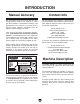
INTRODUCTION Manual Accuracy Contact Info We are proud to offer this manual with your new machine! We've made every effort to be exact with the instructions, specifications, drawings, and photographs of the machine we used when writing this manual. However, sometimes errors do happen and we apologize for them. We stand behind our machines. If you have any service questions, parts requests or general questions about the machine, please call or write us at the location listed below.
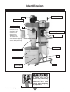
Identification Filter Brush Handle Motor Blower Housing Inlet Restrictor Note: The inlet restrictor is only installed if dust collector is to be used on a 20 Amp-110 Volt circuit and circuit breaker tripping occurs during start-up. Inlet Remote Magnetic Switch Canister Filter Collection Bag Cyclone Funnel Stand Collection Drum Drum Ground Wire Caster Figure 1. Identification.
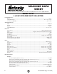
Machine Data Sheet mACHIne dAtA sHeet Customer Service #: (570) 546-9663 • To Order Call: (800) 523-4777 • Fax #: (800) 438-5901 model G0703 1-1/2 HP CyClone dust ColleCtor Product Dimensions: Weight ........................................................................................................................................................................... 177 lbs. Length/Width/Height .............................................................................................................
Bag Information Number of Lower Bags ...................................................................................................................................................1 Lower Bag Capacity .........................................................................................................................................2.66 cu. ft. Lower Bag Diameter...........................................................................................................................................
SECTION 1: SAFETY For Your Own Safety, Read Instruction Manual Before Operating this Machine The purpose of safety symbols is to attract your attention to possible hazardous conditions. This manual uses a series of symbols and signal words intended to convey the level of importance of the safety messages. The progression of symbols is described below. Remember that safety messages by themselves do not eliminate danger and are not a substitute for proper accident prevention measures.
Safety Instructions for Machinery 7. ONLY ALLOW TRAINED AND PROPERLY SUPERVISED PERSONNEL TO OPERATE MACHINERY. Make sure operation instructions are safe and clearly understood. 8. KEEP CHILDREN/VISITORS AWAY. Keep all children and visitors away from machinery. When machine is not in use, disconnect it from power, lock it out, or disable the switch to make it difficult for unauthorized people to start the machine. 9. UNATTENDED OPERATION.
Additional Safety Instructions for Dust Collectors 1. MACHINE USE. This machine is intended to only collect wood dust and chips from woodworking machines. Do not use this dust collector as a vacuum or with machines producing dust/chips from metal, asbestos products, lead paint, silica or any products that are not natural wood or man-made wood products, such as plywood or particle boards. 2. WEAR RESPIRATOR.
SECTION 2: CIRCUIT REQUIREMENTS 110/220V Operation Power Connection Device The type of plug required to connect your machine to power depends on the type of service you currently have or plan to install. We recommend using one of the plugs shown in Figure 2. Serious personal injury could occur if you connect the machine to power before completing the setup process. DO NOT connect the machine to the power until instructed later in this manual.
SECTION 3: SETUP This machine presents serious injury hazards to untrained users. Read through this entire manual to become familiar with the controls and operations before starting the machine! Wear safety glasses during the entire setup process! Items Needed for Setup The following items are needed to complete the setup process, but are not included with your machine: Description Qty • Assistants.................................................... 1 • Safety Glasses...................
Inventory After all the parts have been removed from the boxes, you should have the following items: Machine Inventory (Figure 3): Qty A. Dust Collector & Filter Assembly................. 1 B. Control Box Assembly................................. 1 B A Figure 3. Machine inventory. Stand and Drum Inventory (Figure 4): Qty C. Main Collection Drum.................................. 1 D. Collection Drum Extension..........................
Site Considerations Weight Load Physical Environment Refer to the Machine Data Sheet for the weight of your machine. Make sure that the surface upon which the machine is placed will bear the weight of the machine, additional equipment that may be installed on the machine, and the heaviest workpiece that will be used. Additionally, consider the weight of the operator and any dynamic loading that may occur when operating the machine.
Assembly To assemble your dust collector, do these steps: 1. Invert the stand, place one 3⁄8" lock washer on four caster wheel studs, and thread each caster stud into the stand (Figure 7). 2. 6. Position the stand onto the dust collector housing, and install one 5⁄16"-18 x 11⁄2" hex bolt and flat washer on each side of the stand at the to serve as pivot bolts (see Figure 9 for location). 7. Using a 5⁄16" wrench, snug both hex bolts. Using a 3⁄8" wrench, tighten each caster stud.
10. With the help of an assistant, raise the dust collector to the upright position, and install the handle (Figure 11) with (4) 5⁄16"-18 x 3⁄4" hex bolts and 5⁄16" washers. Figure 11. Installing the hand rail. 11. Engage the filter-element crank (Figure 12) with the shaft, and secure it in place with one 5 ⁄16"-18 x 3⁄4" hex bolt and one flat washer. 12. Attach the casters to the bottom of the drum using (4) 3⁄8"-16 hex nuts, (4) 3⁄8" flat washers, and (4) 3⁄8" lock washers (Figure 13). Figure 13.
14. Place the drum extender onto the drum so one latch is oriented with the drum spout as shown in Figure 15. 16. Place the dust bag seat into the duct collection drum as illustrated in Figure 17. Figure 17. Installing the dust collection bag seat. Figure 15. Drum extender and spout alignment. 15. Secure the drum extender to the drum with the drum clamp (Figure 16), and tighten the clamp with a 1⁄2" wrench. 17. Insert the rubber seal over the top lip of the drum rim (Figure 18).
. Install the dust collection bag into the collection drum as illustrated in Figure 19. 20. Connect one end of the 1" hose and the 7" hose to the collection drum (Figure 21). Ground Wire Figure 19. Bag installation. 19. Place the drum lid onto the drum, and roll the drum under the cyclone port so the drum spout is facing toward the dust collector, as illustrated in Figure 20. Figure 21. Hose and bag installed. 21.
Test Run When the assembly is complete, test run your dust collection system to make sure it operates properly. NOTICE If using a 20-amp, 110-volt power supply circuit instead of a 30-amp, 110-volt or a 15-amp, 220-volt circuit, the machine may cause the power supply circuit breaker to trip. If this occurs, you must install the included 6" x 5" inlet restrictor to lower motor load and current draw. 5. Press the ON/OFF button to turn the machine ON.
SECTION 4: COLLECTION SYSTEM System Setup Duct Material The Model G0703 is designed to collect dust from one machine at a time. This can be accomplished by either connecting it to one machine at a time or by connecting it to multiple machines and using blast gates to control which branch is active. You have many choices regarding main line and branch line duct material.
There are a number of options when it comes to metal duct, but metal duct that is specially manufactured for dust collection is the best choice. When selecting your metal duct, choose high quality metal duct with smooth welded internal seams that will minimize airflow resistance. This type of duct usually connects to other ducts or elbows with a simple, self-sealing clamp, is very quick and easy to assemble, and can be readily dismantled and re-installed.
Always guard against static electrical build up by grounding all dust collection lines. Be sure that you extend the bare copper wire down all branches of the system. Do not forget to connect the wires to each other with wire nuts when two branches meet at a “Y” or “T” connection. Ensure that the entire system is grounded. If using plastic blast gates to direct air flow, the grounding wire must be jumped (Figure 26) around the blast gate without interruption to the grounding system.
SECTION 5: OPERATIONS General Operation Damage to your eyes, lungs, and ears could result from using this machine without proper protective gear. Always wear safety glasses, a respirator, and hearing protection when operating this machine. This cyclone dust collector creates a vortex of incoming air that extracts heavy wood chips (Figure 28) and large dust particles and drops the them into the steel drum below, which is lined with a plastic bag.
Remote Control Operation A remote control receiver and hand-held controller (Figure 29) allows the dust collector to be turned ON and OFF from across the room up to 75-feet away, providing that direct line-of-sight is maintained. The Model G0703 is equipped with an overload indicator light. If the dust collector experiences an overload this light comes on and the machine shuts down.
ACCESSORIES SECTION 6: ACCESSORIES P0703088—220V Mag Switch Installing this mag switch will allow you to run the G0703 on 220V single-phase power. To convert the dust collector to 220V, just remove the 110V switch, install this one in its place, and rewire the motor. It’s as simple as that! H8174—Cyclone Bag Holder H8469—Replacement bags (5 Pack) The cyclone bag holder is a specially designed metal piece that keeps an empty bag from being pulled up into the cyclone.
H1052—Clear Flexible Hose 4" x 10' G1536—Black Flexible Hose 4" x 10' G3179—Heavy-Duty Clear Flex Hose 4" x 10' G8830—Hose Hanger 4 1⁄2" G1552—Y-Fitting 4" x 4" x 4" G1545—90° Elbow 4" G2482—Hose Coupler (Splice) 4" G2974—Wire Hose Clamp 4" G1843—Plastic Blast Gate 4" G4679—Anti-Static Grounding Kit We've hand picked a selection of commonly used dust collection components for machines with 4" dust ports.
SECTION 7: MAINTENANCE Cleaning Filter Always disconnect power to the machine before performing maintenance. Failure to do this may result in serious personal injury. The Model G0703 dust collector has a hand-crank (Figure 38) driven filter flap system for removing any built-up dust from the filter pleats. Schedule For optimum performance from your machine, follow this maintenance schedule and refer to any specific instructions given in this section.
SECTION 8: SERVICE Review the troubleshooting and procedures in this section to fix or adjust your machine if a problem develops. If you need replacement parts or you are unsure of your repair skills, then feel free to call our Technical Support at (570) 546-9663. Troubleshooting Motor & Electrical Symptom Possible Cause Machine does not start or a breaker trips. 1. Power supply switched OFF or is at fault. Machine has vibration or noisy operation. 1. Motor or component is loose. 1.
Dust Collector Operation Symptom Possible Cause Possible Solution Loud, repetitious noise, or excessive vibration coming from dust collector. 1. Dust collector is not on a flat surface and wobbles. 2. Impeller is damaged and unbalanced. 1. Stabilize the dust collector. 3. The motor mounting or housing connections are loose. 4. Impeller is loose on the motor shaft. 5. Motor fan cover is dented, causing the motor fan to hit the cover while spinning.
SECTION 9: WIRING These pages are current at the time of printing. However, in the spirit of improvement, we may make changes to the electrical systems of future machines. Study this section carefully. If there are differences between your machine and what is shown in this section, call Technical Support at (570) 546-9663 for assistance BEFORE making any changes to the wiring on your machine. Wiring Safety Instructions 1. SHOCK HAZARD.
110V Wiring Diagram Neutral W L5-30 Plug (As Recommended) MOTOR 110V G Hot Ground 110 VAC (Prewired) Run Capacitor 40MFD 250VAC Start Capacitor 300MFD 125VAC 1 3 2 4 GND A1 A2 1L1 3L2 5L3 13NO NHD C-09D 110V 2T1 4T2 14NO 6T3 A2 NHD NTH-21 17 18 19 20 98 97 2T1 R O 21 96 4T2 95 6T3 MAGNETIC SWITCH ASSY Model G0709 (Mfg.
220V Wiring 220V Wiring Diagram Ground G Gn Hot Bl Wt MOTOR 220V 220 VAC MOTOR Hot 6-15 Plug (Rewired 220V) Run Capacitor 40MFD 250VAC Start Capacitor 300MFD 125VAC 4 3 2 1 GND A2 A1 1L1 3L2 5L3 13NO NHD C-09D 220V 2T1 4T2 14NO 6T3 A2 9 8 NHD NTH-11 10 98 97 2T1 R O 11 96 4T2 95 6T3 MAGNETIC SWITCH ASSY -32- READ ELECTRICAL SAFETY ON PAGE 30! OL_NO AC OUT AC IN CIRCUIT BOARD 220V ON/OFF SWITCH Model G0703 (Mfg.
Electrical Component Locations Motor Junction Box Location Magnetic Switch and Circuit Board Location Figure 39. Electrical component locations. Model G0709 (Mfg.
Parts SECTION 10: PARTS Main 1-1 1-4 1-2 1 1-3 44 1-5 2 47 48 5 7 6 43 46 45 90 56 49 3 8 4 51 50 10-1 89 4 9 63 10 13-1 52 70 54 57 14 15 69 55 53 56 71 23 24 77 58 59 60 61 62 72 73 76 82 17 27 28 75-1 75-4 64 75-2 78 75-5 79 83 81 80 40 84 88-3 88-2 25 94 26 30 33 34 86 86-1 36 38 85 37 23 24 41 38-1 39 -34- 29 35 31 87 88-1 21 32 220V Conversion Kit 88 20 96 75-3 65 18 19 93 94 95 74 92 16-1 16 22 66 67 31 75 91 22-1 68
Main Parts List REF PART # DESCRIPTION REF PART # DESCRIPTION 1 1-1 1-2 1-3 1-4 1-5 2 3 4 5 6 7 8 9 10 10-1 11 12 13 13-1 14 15 16 16-1 17 18 19 20 21 22 22-1 23 24 25 26 27 28 29 30 31 32 33 34 35 36 37 38 38-1 39 40 41 42 43 44 45 46 47 48 MOTOR 1-1/2 HP 110/220V 1PH MOTOR FAN COVER MOTOR FAN MOTOR JUNCTION BOX S CAPACITOR 300M 125V 1-1/2 X 3-1/8 R CAPACITOR 40M 250V 1-3/8 X 2-3/8 MOTOR GASKET FLAT WASHER 5/16 HEX BOLT 5/16-18 X 3/4 MOTOR MOUNTING PLATE FLAT WASHER 5/16 HEX BOLT 5/16-18 X 3/4 IMPELLE
Machine Labels 100 102 101 107 106 103 105 104 108 REF PART # DESCRIPTION REF PART # DESCRIPTION 100 101 102 103 104 MACHINE ID LABEL HEARING HAZARD LABEL READ MANUAL LABEL EYE/LUNG HAZARD LABEL MODEL NUMBER LABEL 105 106 107 108 ELECTRICITY LABEL INTLET HAZARD LABEL GRIZZLY GREEN TOUCH-UP PAINT GRIZZLY.COM LABEL RED P0703100 PLABEL-15A PLABEL-12A PLABEL-57 P0703104 PLABEL14 PLABEL59 P0703107 P0703108 Safety labels warn about machine hazards and ways to prevent injury.
WARRANTY CARD Name _____________________________________________________________________________ Street _____________________________________________________________________________ City _______________________ State _________________________ Zip _____________________ Phone # ____________________ Email ________________________ Invoice # _________________ Model # ____________________ Order # _______________________ Serial # __________________ The following information is given on a voluntary basis.
FOLD ALONG DOTTED LINE Place Stamp Here GRIZZLY INDUSTRIAL, INC. P.O.
WARRANTY AND RETURNS Grizzly Industrial, Inc. warrants every product it sells for a period of 1 year to the original purchaser from the date of purchase. This warranty does not apply to defects due directly or indirectly to misuse, abuse, negligence, accidents, repairs or alterations or lack of maintenance.
Buy Direct and Save with Grizzly ® – Trusted, Proven and a Great Value! ~Since 1983~ Visit Our Website Today For Current Specials! ORDER 24 HOURS A DAY! 1-800-523-4777