MODEL G0705 Mill/Drill w/Stand Owner's Manual Copyright © March, 2010 By Grizzly Industrial, Inc. Revised December, 2010 (JB) Warning: No portion of this manual may be reproduced in any shape or form without the written approval of Grizzly Industrial, inc.
This manual provides critical safety instructions on the proper setup, operation, maintenance, and service of this machine/tool. Save this document, refer to it often, and use it to instruct other operators. Failure to read, understand and follow the instructions in this manual may result in fire or serious personal injury—including amputation, electrocution, or death. The owner of this machine/tool is solely responsible for its safe use.
Table of Contents INTRODUCTION................................................ 2 Manual Accuracy............................................ 2 Contact Info.................................................... 2 Machine Description....................................... 2 Identification.................................................... 3 SECTION 5: ACCESSORIES.......................... 35 SECTION 1: SAFETY........................................ 7 Safety Instructions for Machinery...................
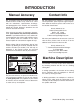
INTRODUCTION Manual Accuracy Contact Info We are proud to offer this manual with your new machine! We've made every effort to be exact with the instructions, specifications, drawings, and photographs of the machine we used when writing this manual. However, sometimes we still make an occasional mistake. We stand behind our machines. If you have any service questions, parts requests or general questions about the machine, please call or write us at the location listed below.
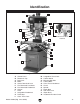
Identification C B A D E V W F U T H G S R Detail of left side of machine I J J K M K L Q M N P O Figure 1. Model G0705 identification. A. B. C. D. E. F. G. H. I. J. K. L. Control Panel Drawbar & Cap Belt Cover Motor Coarse Downfeed Lever Fine Downfeed Lock Knob Fine Downfeed Handwheel Column Table Longitudinal Handwheel Table Stop Cross Travel Lock Model G0705 (Mfg. since 09/09) M. N. O. P. Q. R. S. T. U. V. W.
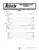
MACHINE DATA SHEET Customer Service #: (570) 546-9663 · To Order Call: (800) 523-4777 · Fax #: (800) 438-5901 MODEL G0705 DRILL/MILL WITH STAND 29 INCH X 8 INCH TABLE Product Dimensions: Weight.............................................................................................................................................................. 617 lbs. Length/Width/Height...........................................................................................................
Main Specifications: Operation Info Spindle Travel.................................................................................................................................... 4-11/16 in. Longitudinal Table Travel.................................................................................................................19-11/16 in. Cross Table Travel....................................................................................................................................... 9 in.
Features: Front mounted digital display Calibrated depth stop Fine feed downfeed control, graduated in 0.001 in. Coolant trough Replaceable brushes on universal motor Quill moves 0.108 in. per revolution of fine feed handwheel Table moves 0.100 in. per revolution of handwheel Accessories Included: Drill chuck 1/16-1/2 in.
SECTION 1: SAFETY For Your Own Safety, Read Instruction Manual Before Operating this Machine The purpose of safety symbols is to attract your attention to possible hazardous conditions. This manual uses a series of symbols and signal words intended to convey the level of importance of the safety messages. The progression of symbols is described below. Remember that safety messages by themselves do not eliminate danger and are not a substitute for proper accident prevention measures.
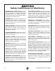
Safety Instructions for Machinery DISCONNECTING POWER SUPPLY. Always disconnect machine from power supply before servicing, adjusting, or changing cutting tools (bits, blades, cutters, etc.). Make sure switch is in OFF position before reconnecting to avoid an unexpected or unintentional start. INTENDED USE. Only use the machine for its intended purpose and only use recommended accessories. Never stand on machine, modify it for an alternative use, or outfit it with nonapproved accessories. STABLE MACHINE.
Additional Safety for Mill/Drills UNDERSTANDING CONTROLS. Make sure you understand the use and operation of all controls. Safety accessories. Always use a chip guard in addition to your safety glasses when milling to prevent bodily injury. WORK HOLDING. Before starting the machine, be certain the workpiece has been properly clamped to the table. NEVER hold the workpiece by hand when using the mill. CHUCK KEY SAFETY. Always remove your chuck key, drawbar wrench, and any service tools immediately after use.
SECTION 2: POWER SUPPLY Availability Circuit Information Before installing the machine, consider the availability and proximity of the required power supply circuit. If an existing circuit does not meet the requirements for this machine, a new circuit must be installed. To minimize the risk of electrocution, fire, or equipment damage, installation work and electrical wiring must be done by a qualified electrician in accordance with all applicable codes and standards.
Grounding Requirements This machine MUST be grounded. In the event of certain malfunctions or breakdowns, grounding reduces the risk of electric shock by providing a path of least resistance for electric current. For 220V operation: This machine is equipped with a power cord that has an equipment-grounding wire and a grounding plug (similar to the figure below).
Contactor Information For 220V, Contactor Type 3TB41 22-OX, Coil Voltage 220V/60Hz/1PH, SIEMENS For 110V, Contactor Type 3TB41 22-OX, Coil Voltage 110V/60Hz/1PH, SIEMENS (Contactor is wired the same for 110V/220V) U1 U2 U2 V1 U2 V1 U2 V1 The Model G0705 can be converted for 110V To Motor operation. This conversion job consists of disV2 connecting the machine from the power source, replacing the contactors and power indicator lamp, and rewiring the motor.
4. Remove the screws that secure the brass contactor mounting plate to the back of the electrical box, then pull the contactors out to access the gray tab shown in Figure 7. Pull outward on the gray tab to release each contactor from the mounting plate. 10. Locate the terminal block located in the motor junction box, shown in Figure 8. Motor 220V Terminal Block 110V Terminal Block Jumper Position.
11. Use a Phillips screwdriver to remove the screws that secure the two metal jumpers to the terminal block, as shown in Figure 9, then remove both jumpers. Be careful not to mix up the locations of any of the wires while you do so. 14. Install a NEMA 5-20 plug such as the one shown in Figure 3 onto the power cord, as illustrated in Figure 10. Refer to SECTION 8: WIRING starting on Page 45 for detailed wiring diagrams. Cord Rewired for 110V Neutral Hot Ground L5-30 Plug (As Recommended) Figure 10.
SECTION 3: SETUP Needed for Setup This machine presents serious injury hazards to untrained users. Read through this entire manual to become familiar with the controls and operations before starting the machine! Wear safety glasses during the entire setup process! The Model G0705 is a heavy machine. Serious personal injury may occur if safe moving methods are not used. To be safe, get assistance and use power equipment to move the shipping crate and remove the machine from the crate.
Inventory The following is a description of the main components shipped with your machine. A B Crate Contents (Figures 11 & 12) Qty A. Cabinet Base............................................... 1 B. Machine....................................................... 1 C. Toolbox........................................................ 1 D. Drill Chuck B16 1–13mm............................. 1 E. Drill Chuck Arbor R8–B16........................... 1 F. Lug Wrench................................................
Cleanup Gasoline and petroleum products have low flash points and can explode or cause fire if used to clean machinery. Avo i d u sing t h e s e p r o d u c t s to c l e a n m a c hin e r y. The unpainted surfaces of your machine are coated with a heavy-duty rust preventative that prevents corrosion during shipment and storage. This rust preventative has been your machine's close ally and guardian since it left the factory.
Site Considerations Weight Load Physical Environment Refer to the Machine Data Sheet for the weight of your machine. Make sure that the surface upon which the machine is placed will bear the weight of the machine, additional equipment that may be installed on the machine, and the heaviest workpiece that will be used. Additionally, consider the weight of the operator and any dynamic loading that may occur when operating the machine.
Mounting Options Before you place your machine on the cabinet, we recommend you consider the following options for leveling and mounting it. Deciding on a method for mounting and leveling before placing the machine on the cabinet will make the process much safer and easier. Using the Included Leveling Bolt 1. Thread one M12-1.75 x 40 hex bolt with one M12-1.75 hex nut into the bolt mounting hole on each corner of the base, as shown in Figure 15. x4 Option 1: Use the included leveling bolts.
Using Machine Mounts Mounting to Shop Floor Using machine mounts, shown in Figure 16, gives the advantage of fast leveling and vibration reduction. The large size of the foot pads distributes the weight of the machine to reduce strain on the floor. Although not required, we recommend that you mount the cabinet to the floor. Because this is an optional step and floor materials may vary, mounting hardware is not included.
Mounting to a Workbench If you are placing the machine on an existing workbench, it must be securely attached to the workbench. The strongest mounting option is a "Through Mount" where holes are drilled all the way through the workbench, and hex bolts, washers, and hex nuts are used to secure machine to the workbench. Assembly Assembly of the Model G0705 consists of attaching the three handwheel handles to the machine. To assemble your machine: 1.
Moving & Placing Machine To move your machine into position: 1. 4. Unbolt the machine from the pallet, then with an assistant steadying the machine to prevent it from swinging, lift it slightly off of the pallet. Use the cross handwheel to move the table forward or backward as necessary to balance the machine so it hangs as close to level as possible. Move the shipping crate next to the workbench or cabinet. 5. Lift the machine and carefully place it onto the cabinet or workbench. 2.
Test Run Once the assembly is complete, test run your machine to make sure it runs properly and is ready for regular operation. The test run consists of verifying the following: 1) The motor powers up and runs correctly and 2) the stop button safety feature works correctly. If, during the test run, you cannot easily locate the source of an unusual noise or vibration, stop using the machine immediately, then review Troubleshooting on Page 41.
6. 7. Repeat Step 5 with the REVERSE button. The spindle should rotate in the opposite direction. 8. Press the EMERGENCY STOP button to stop the machine. Allow the spindle to stop rotating before proceeding. 9. Break-In Press the STOP button to stop the machine. Allow the spindle to stop rotating before proceeding. WITHOUT resetting the switch, press the FORWARD button. The machine should not start. —If the machine does not start, the EMERGENCY STOP button safety feature is working correctly.
SECTION 4: OPERATIONS Operation Overview To reduce the risk of serious injury when using this machine, read and understand this entire manual before beginning any operations. Damage to your eyes and lungs could result from using this machine without proper protective gear. Always wear safety glasses and a respirator when operating this machine. The purpose of this overview is to give the operator a basic understanding of how this machine operates—the big picture view of normal operations on this machine.
8. For milling operations, loosens the quill lock lever and uses the quill feed lever or the fine feed knob to set the cutting tool height according to the workpiece. Then, presses the FORWARD or REVERSE button to start the spindle and uses the table handwheels to move the table so the cutter removes material evenly from the workpiece.
Longitudinal Travel Handwheels: Control longitudinal (X-Axis) travel of the table. Head Crank: Changes the elevation of the entire headstock. Cross Travel Handwheel: Controls cross (Y-Axis) travel of the table. Table Locks: Lock the table in position along their respective axes. Travel Stops: Limit longitudinal table travel. Longitudinal Travel Handwheels Travel Stops Head Crank Figure 27. Head crank. Table Locks Cross Travel Handwheel Figure 25. Table travel controls.
Calculating Spindle Speed for Milling Before calculating the spindle speed for a milling operation, you must first understand the concept of "Cutting Speed" and how it differs from "Spindle Speed." Cutting speed is defined as the rate at which a cutting tool's edge passes across the surface of a workpiece. It is generally measured in "surface feet per minute" (sfm), which represents the theoretical distance the cutting edge would travel across the material in a straight line in one minute.
Speed Changes 3. Open the belt cover, then loosen the two idler cap screws (Figure 31) that hold the idler pulley in place so it can move freely. The Model G0705 is capable of twelve different speed settings. Different types of cuts and materials require varying speeds. Refer to the chart in Figure 29 for appropriate cutting speeds. Idler Cap Screws Tools Needed Qty Hex Wrench 6mm............................................... 1 To change spindle speeds: 1. DISCONNECT MACHINE FROM POWER! 2.
Calculating Spindle Speed for Drilling Using the Drill Bit Speed Chart Lubrication Suggestions The chart shown in Figure 33 is intended as a guide only. Always follow the manufacturer's speed recommendations if provided with your drill bits, cutters, or hole saws. Exceeding the recommended speeds may be dangerous to the operator. Wood............................................................None Plastics.............................................Soapy Water Brass................................
Spindle Height The Model G0705 has coarse downfeed levers and a micro-adjustment handwheel. To operate the downfeed levers, simply pull forward and down on the lever nearest you. The spindle will go down until you stop pulling or until it hits the depth stop. To operate the micro-adjustment handwheel: 1. Tighten the locking knob located on the center of the hub for the downfeed levers (Figure 34). This transfers control from the downfeed levers to the micro-adjustment handwheel.
Loading Tooling The Model G0705 features an R-8 spindle that accepts R-8 collets and arbors. 6. If you're using a collet, insert the cutter in the hole at the bottom of the collet. Be sure to protect your hands from the cutter with leather gloves or a shop rag. 7. To install tooling: 1. DISCONNECT MACHINE FROM POWER! —If the drawbar bottoms out in the tooling and will tighten no farther before the tooling is tight in the spindle, tighten the drawbar lock nut to secure the tooling in the spindle. 2.
Drill Chuck Arbor Collet Adapters Your machine includes an R-8 drill chuck arbor and MT#3 drill chuck. Before use, the drill chuck must be installed onto the arbor. This drill chuck installation is intended to be semi-permanent. The Model G0705 includes two adapters that will allow the use of MT#3 and MT#2 tooling. A drift key is also included to aid in the separation of the adapters and any installed tooling.
Headstock Position Depth Stop The headstock height and rotation on the Model G0705 can be adjusted for various applications. For increased quill rigidity and reduced vibrations, which will produce the best results, keep the quill fully retracted and set the headstock as low as possible. The depth stop is used to limit the range of downward movement by the drill bit or cutter. Maximum depth is 4 11⁄16". To calibrate the depth stop: 1.
Table Travel The mill/drill table moves in the longitudinal (X-axis) and cross (Y-axis) directions. Longitudinal Feed The handwheels shown in Figure 42 at each end of the table move the table longitudinally (X-axis). These handwheels will move the table in both directions. One complete revolution of either handwheel moves the longitudinal feed 0.100". A scale on the front of the table is used when a high tolerance is not required.
ACCESSORIES SECTION 5: ACCESSORIES H2689—R-8 Quick Change Collet Set An affordable quick change collet system with ultra precision. These spring collets are hardened and ground to exacting tolerances and offer incredible holding power. This set includes an R-8 arbor and nut, spanner wrench, plastic carrying case and collets sized 1⁄ 8", 1⁄4", 3 ⁄ 8", 1⁄ 2", 5 ⁄ 8", 3 ⁄4", 7⁄ 8", and 1". What's more, the nut features a self-ejecting rim! A set like this will truly speed up any tool changing process.
G2861—Face Mill G4051—Carbide Insert for Face Mill This 21/2" Face Mill accepts four carbide inserts (not included). Comes with an R-8 arbor. G5641—1-2-3 Blocks G9815—Parallel Set H5556—Edge Finder Set G5641 H5556 G9815 Figure 49. G2861 Face Mill. G9760—20-PC. 2 & 4 Flute TiN End Mill Set. Includes these sizes and styles in two and four flute styles: 3/16", 1/4", 5/16", 3/8", 7/16", 1/2", 9/16", 5/8", 3 /8", 11/16", and 3/4". Figure 52. G5641 1-2-3 Blocks, G9815 Parallel Set, and H5556 Edge Finder Set.
SECTION 6: MAINTENANCE Always disconnect power to the machine before performing maintenance. Failure to do this may result in serious personal injury. Schedule For optimum performance from your machine, follow this maintenance schedule and refer to any specific instructions given in this section. Daily Check: • Make sure mill/drill is disconnected from power when not in use. • Check for loose mounting bolts. • Make sure mill/drill is clean and lubricated. • Check for worn or damaged wires.
Lubrication Table Leadscrews Every six months, or more frequently under heavy use, clean and lubricate the leadscrews. Points requiring periodic lubrication are: A. Column. A light film of oil (Mobil Vactra 2 or ISO 68 equivalent) will smooth action and prevent rust and corrosion. Items Needed: Qty Mobil Vactra 2 or ISO 68 Equivalent.................. 1 Stiff-Bristled Nylon Brush for Cleaning............... 1 Mineral Spirits.................. As needed for cleaning Shop Rags.......................
V-Belts 5. Using the longitudinal handwheel, move the table as far to one side as possible. 6. Use mineral spirits and a brush to clean as much of the oil and debris as possible off of the longitudinal leadscrew shown in Figure 56. Allow the leadscrew to dry. Inspect regularly for tension and wear. Refer to Figure 57 for proper belt tension. Belt deflection should be approximately 1⁄4" under moderate pressure.
Troubleshooting SECTION 7: SERVICE Review the troubleshooting and procedures in this section to fix or adjust your machine if a problem develops. If you need replacement parts or you are unsure of your repair skills, then feel free to call our Technical Support at (570) 546-9663. Troubleshooting Symptom Possible Cause Possible Solution Machine does not start. 1. Wall fuse/circuit breaker is blown/tripped. 5. Machine power switch is at fault. 6. Motor is at fault. 1.
Symptom Possible Cause Tool slips in collet. 1. Collet is not fully drawn up into 1. Tighten drawbar. spindle taper. 2. Measure tool shank diameter and match with 2. Wrong size collet. appropriate diameter collet. 3. Debris on collet or in spindle taper. 3. Clean collet and spindle taper. 4. Lessen depth of cut and allow chips to clear. 4. Taking too big of a cut. 5. Reverse feed direction to avoid climb cuts. 5. Making a climb cut. Breaking tools or cutters. 1. Spindle speed is too slow/feed rate 1.
Gibs Return Spring Gibs are wedge-shaped pieces of metal that fill the gap between the dovetailed ways of the machine. By adjusting the position of the gib in the gap, you can remove any play that might exist between the adjacent components. The gibs are pre-adjusted at the factory but due to storage, break-in, and usage, they may require adjustment. Tools Needed Qty Standard #2 Screwdriver.................................... 1 To adjust the table gibs: 1. DISCONNECT MILL/DRILL FROM POWER! 2.
4. Put on gloves and pull the spring cover out enough so the notches just clear the roll pin. HOLD THE SPRING COVER TIGHTLY or the force of the spring will spin it out of your hands. 5. Rotate the cover to adjust the tension. Push the cover back in to engage the roll pin in one of the notches, as shown in Figure 60. Tools Needed Qty 3mm Hex Bit....................................................... 1 6" Extension for Hex Bit..................................... 1 Ratchet for Hex Bit.....................
SECTION 8: WIRING These pages are current at the time of printing. However, in the spirit of improvement, we may make changes to the electrical systems of future machines. Study this section carefully. If there are differences between your machine and what is shown in this section, call Technical Support at (570) 546-9663 for assistance BEFORE making any changes to the wiring on your machine. Wiring Safety Instructions SHOCK HAZARD.
G0705 Wiring Diagram Motor 220V 110V Terminal Block Jumper Position. (Wire positions are the same for 110V/220V) U1 Z2 W2 V1 U2 To Electrical Box Run Capacitor 20 MFD 450 VAC U1 Z2 U2 W2 V1 U2 V2 Start Capacitor 150 MFD 250 VAC Z1 Z1 U1 V1 W1 V2 W1 V2 PE Ground To Electrical Box Hot Cord Rewired for 110V 220 VAC Neutral Hot Hot Ground -46- L5-30 Plug (As Recommended) Ground 6-20 Plug Model G0705 (Mfg.
G0705 Wiring Diagram (Continued) Contactor Information For 220V, Contactor Type 3TB41 22-OX, Coil Voltage 220V/60Hz/1PH, SIEMENS For 110V, Contactor Type 3TB41 22-OX, Coil Voltage 110V/60Hz/1PH, SIEMENS (Contactor is wired the same for 110V/220V) To Motor U1 U2 U2 V1 U2 V1 V1 U2 V2 V2 14NO 2T1 22NC 4T2 V2 6T3 N N 13NO V1 A2 7 32NC 5 44NO CONTACTOR SIEMENS KM1 U1 21NC 3 L L 4T2 L 12A PE 5 6T3 N N N N N L 5 14NO 22NC 32NC CONTACTOR SIEMENS KM2 7 6 3L2 31NC 43NO 8 5
-48- 11-7 11-6 11-5 69 68 70 54 53 41 42 43 55 44 57 39 12 14 11-4 11-1 11-1 11-2 11-3 67 17 37 61 16 19 66 56 61 40 7-2 7-3 7-2 7-4 7-1 11 15 7 6 5 13 9 8 31 23 23-5 23-3 33 32 65 22 23-2 25 24 99 45 26 23-1 93-1 93-4 27 93-5 93-3 91 77 76 102 72 75 100 101 29 93-2 23-3 64 46 48 23-4 47 62 63 20 62 63 58 60 49 59 113-1 113 35 18 10 52 21 1 51 28 96 74 78 90 4 3 2 97 94 79 97 92 98 83 82 80 71 81 93 94 95 86
Headstock Parts List REF PART # DESCRIPTION REF PART # DESCRIPTION 1 2 3 4 5 6 7 7-1 7-2 7-3 7-4 8 9 10 11 11-1 11-2 11-3 11-4 11-5 11-6 11-7 12 13 14 15 16 17 18 19 HEAD CASTING DRAWBAR SPINDLE LOCK NUT SPINDLE PULLEY OUTER BEARING PLATE CAP SCREW 1/4-20 x 1/2 SPINDLE TAPER SLEEVE SET SPINDLE TAPER SLEEVE BALL BEARING 6009ZZ SPACER 74MM EXT RETAINING RING 41MM INT RETAINING RING 80MM RUBBER FLANGE QUILL CLAMP QUILL ASSEMBLY SPANNER NUT TOOTHED SPINDLE WASHER TAPERED ROLLER BEARING 30206 SPINDLE SLEEVE
Headstock Parts List (continued) REF PART # DESCRIPTION REF PART # DESCRIPTION 48 49 51 52 53 54 55 56 57 58 59 60 61 62 63 64 65 66 67 68 69 70 71 72 74 75 76 77 78 79 CAP SCREW 1/4-20 X 3/4 ELEVATION CRANK CLAMP HANDLE OUTER QUILL CLAMP INNER QUILL CLAMP QUILL CLAMP SPACER QUILL CLAMP HANDLE SCREW KEY HEX NUT 3/8-16 COMPRESSION SPRING BELT TENSION PIN RUBBER PAD HEX BOLT 5/8-11 X 6 FLAT WASHER 5/8 HEX NUT 5/8-11 HEADSTOCK WRENCH LOCK HANDLE M8-1.
207 229 Model G0705 (Mfg.
Base Parts List REF PART # DESCRIPTION REF PART # DESCRIPTION 201 202 203 204 205 206 207 209 210 211 212 213 216 217 218 219 220 221 222 223 224 225 TABLE T-NUT 1/4-20 TABLE STOP CAP SCREW 1/4-20 X 1/2 TAP-IN BALL OILER 1/4 TABLE HANDWHEEL HANDLE HANDWHEEL COLLAR DOWEL PIN LEFT FLANGE CAP SCREW 5/16-18 X 1 LONGITUDINAL HALF NUT LONGITUDINAL LEADSCREW KNURLED THUMBSCREW M5-.
Electrical Components Breakdown and List 301 302 2T1 4T2 6T3 14NO 22NC 32NC 44NO A2 CONTACTOR SIEMENS KM1 220V 303 2T1 A1 13NO 1L1 21NC 3L2 31NC 5L3 43NO 4T2 22NC 6T3 32NC 44NO A2 CONTACTOR SIEMENS KM2 220V 14NO 303 A1 13NO 1L1 21NC 3L2 31NC 5L3 43NO 12A 310 Electrical Box 309 2T1 4T2 6T3 14NO 22NC 32NC 44NO A2 CONTACTOR SIEMENS KM1 110V 308 2T1 31NC 43NO 22NC 6T3 32NC 44NO CONTACTOR SIEMENS KM2 110V 4T2 21NC 31NC 43NO 304 1L1 3L2 4 3 5L3 3 4 FORWARD BUTT
Labels Breakdown and List 403 402 401 404 405 405 406 407 408 409 REF PART # DESCRIPTION REF PART # DESCRIPTION 401 402 403 404 405 MACHINE ID LABEL SAFETY GLASSES LABEL ENTANGLEMENT LABEL READ MANUAL LABEL ELECTRICITY LABEL 406 407 408 409 PUTTY TOUCH UP PAINT CUTTER WARNING LABEL GREEN TOUCH UP PAINT MODEL NUMBER LABEL P0705401 PLABEL-11B PLABEL-55A PLABEL-12C PLABEL-14A PPAINT-11 P0705407 PPAINT-1 P0705409 Safety labels warn about machine hazards and ways to prevent injury.
WARRANTY CARD Name _____________________________________________________________________________ Street _____________________________________________________________________________ City _______________________ State _________________________ Zip _____________________ Phone # ____________________ Email ________________________ Invoice # _________________ Model # ____________________ Order # _______________________ Serial # __________________ The following information is given on a voluntary basis.
FOLD ALONG DOTTED LINE Place Stamp Here GRIZZLY INDUSTRIAL, INC. P.O.
WARRANTY AND RETURNS WARRANTY AND RETURNS Grizzly Industrial, Inc. warrants every product it sells for a period of 1 year to the original purchaser from the date of purchase. This warranty does not apply to defects due directly or indirectly to misuse, abuse, negligence, accidents, repairs or alterations or lack of maintenance.
Buy Direct and Save with Grizzly ® – Trusted, Proven and a Great Value! ~Since 1983~ Visit Our Website Today For Current Specials! ORDER 24 HOURS A DAY! 1-800-523-4777