MODEL G0719 15" DisC Sander w/Brake OWNER'S Manual Copyright © JANUARY, 2011 By Grizzly Industrial, Inc. Warning: No portion of this manual may be reproduced in any shape Or form without the written approval of Grizzly Industrial, inc.
This manual provides critical safety instructions on the proper setup, operation, maintenance, and service of this machine/tool. Save this document, refer to it often, and use it to instruct other operators. Failure to read, understand and follow the instructions in this manual may result in fire or serious personal injury—including amputation, electrocution, or death. The owner of this machine/tool is solely responsible for its safe use.
Table of Contents INTRODUCTION................................................ 2 Manual Accuracy............................................ 2 Contact Info.................................................... 2 Machine Description....................................... 2 Identification.................................................... 3 Machine Data Sheet....................................... 4 SECTION 1: SAFETY........................................ 6 Safety Instructions for Machinery...................
INTRODUCTION Manual Accuracy Contact Info We are proud to offer this manual with your new machine! We've made every effort to be exact with the instructions, specifications, drawings, and photographs of the machine we used when writing this manual. However, sometimes we still make an occasional mistake. We stand behind our machines. If you have any questions or need help, use the information below to contact us. Before contacting, please get the serial number and manufacture date of your machine.
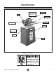
Identification Motor Cast Iron Disc (Sanding Disc Attached) Disc Guard Miter Gauge Work Table On/Off Switch Cabinet Lock Handle (One of Two) Tilt Scale Door Figure 1. Identification. To reduce the risk of serious injury when using this machine, read and understand this entire manual before beginning any operations. Model G0719 (Mfg.
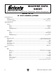
Machine Data Sheet macHine data sHeet © Grizzly Industrial, Inc. • Customer Service: (800) 523-4777 • Website: www.grizzly.com model G0719 15" disc sander w/stand Product Dimensions: Weight ........................................................................................................................................................................... 201 lbs. Length/Width/Height .......................................................................................................................
Main Specifications: Table & Disc Information Table Tilt Range ............................................................................................................................................ +15° to -45° Sanding Disc Diameter.............................................................................................................................................15 in. Sanding Disc Speed ...........................................................................................................
SECTION 1: SAFETY For Your Own Safety, Read Instruction Manual Before Operating this Machine The purpose of safety symbols is to attract your attention to possible hazardous conditions. This manual uses a series of symbols and signal words intended to convey the level of importance of the safety messages. The progression of symbols is described below. Remember that safety messages by themselves do not eliminate danger and are not a substitute for proper accident prevention measures.
DISCONNECTING POWER SUPPLY.Alwaysdisconnect machine from power supply before servicing, adjusting, or changing cutting tools (bits, blades, cutters, etc.). Make sure switch is in OFF positionbeforereconnectingtoavoidanunexpectedorunintentionalstart. APPROVED OPERATION. Untrained operators can be seriously hurt by machinery. Only allow trained or properly supervised people to use machine.
Additional Safety for Disc Sanders AVOID FINGER INJURIES. Never purposely touch the moving sanding disc. Take care to keep fingers away from sanding disc during operations. If the workpiece is small or difficult to hold, use a workpiece holding fixture. Sanding abrasives can quickly remove large amounts of skin! POSITION TABLE CORRECTLY.
SECTION 2: POWER SUPPLY Availability Circuit Information Before installing the machine, consider the availability and proximity of the required power supply circuit. If an existing circuit does not meet the requirements for this machine, a new circuit must be installed. To minimize the risk of electrocution, fire, or equipment damage, installation work and electrical wiring must be done by a qualified electrician in accordance with all applicable codes and standards.
Grounding Requirements This machine MUST be grounded. In the event of certain malfunctions or breakdowns, grounding reduces the risk of electric shock by providing a path of least resistance for electric current. For 220V operation: This machine is equipped with a power cord that has an equipment-grounding wire and a grounding plug (see following figure).
SECTION 3: SETUP Needed for Setup This machine presents serious injury hazards to untrained users. Read through this entire manual to become familiar with the controls and operations before starting the machine! Wear safety glasses during the entire setup process! This machine and its components are very heavy. Get lifting help or use power lifting equipment such as a forklift to move heavy items. The following are needed to complete the setup process, but are not included with your machine.
Inventory A B The following is a description of the main components shipped with your machine. Lay the components out to inventory them. If any non-proprietary parts are missing (e.g. a nut or a washer), we will gladly replace them; or for the sake of expediency, replacements can be obtained at your local hardware store. Main Inventory (Figure 3) Qty A. Sander Assembly......................................... 1 B. Left Side Panel . .......................................... 1 C. Right Side Panel..........
Cleanup The unpainted surfaces of your machine are coated with a heavy-duty rust preventative that prevents corrosion during shipment and storage. This rust preventative works extremely well, but it will take a little time to clean. Be patient and do a thorough job cleaning your machine. The time you spend doing this now will give you a better appreciation for the proper care of your machine's unpainted surfaces.
Site Considerations Weight Load Physical Environment Refer to the Machine Data Sheet for the weight of your machine. Make sure that the surface upon which the machine is placed will bear the weight of the machine, additional equipment that may be installed on the machine, and the heaviest workpiece that will be used. Additionally, consider the weight of the operator and any dynamic loading that may occur when operating the machine.
Assembly 3. When assembling this machine, we recommend tightening fasteners with hand tools only. Air or electric impact tools can easily over-tighten fasteners, causing them to dig into the paint or strip threads Fasten the panel and door assembly to the left and right panels, as shown in Figure 8, using (4) 5⁄16"-18 x 3⁄4" carriage bolts and (4) 5 ⁄16"-18 flange nuts. To assemble the cabinet and mount the machine: 1.
6. With the help of another person, place the sanding unit onto the top of the cabinet, as shown in Figure 10, and fasten it to the cabinet using (4) M8-1.25 x 45 hex bolts and (4) 5 ⁄16" flat washers.
Test Run Once the assembly is complete, test run your machine to make sure it runs properly and is ready for regular operation. 6. Turn the machine OFF. 7. Remove the switch disabling key, as shown in Figure 14. The test run consists of verifying the following: 1) The motor powers up and runs correctly, and 2) the safety disabling mechanism on the switch works correctly.
SECTION 4: OPERATIONS Operation Overview The purpose of this overview is to provide the novice machine operator with a basic understanding of how the machine is used during operation, so the machine controls/components discussed later in this manual are easier to understand. Due to the generic nature of this overview, it is not intended to be an instructional guide.
Attaching Sandpaper Disc Sanding The Model G0719 sander accepts 15" diameter adhesive-backed sanding discs. These are available in a variety of grits. The Model G0719 uses dual-axis miter slot design for increased versatility of workpiece control. The sanding disc sticks to the surface of the cast iron disc platen, using the pressure-sensitive adhesive (PSA) backing. The sandpaper can be replaced without removing the table or dust port. To attach sandpaper: 1.
Figure 17. Example of X-axis sanding. Figure 19. Sanding with table tilted. Note: To perform sanding on compound-angle cuts, tilt the table and rotate the miter gauge to the appropriate angles. Note: To prevent burning the workpiece and overloading the sanding disc, move the workpiece slowly back and forth from the left side of the sanding disc to the center. Figure 18. Angle sanding. -20- Model G0719 (Mfg.
ACCESSORIES SECTION 5: ACCESSORIES Replacement Sanding Discs for Model G0719 MODEL and TYPE GRIT T23357 15" PSA................................................ 60 T23358 15" PSA................................................ 80 T23359 15" PSA.............................................. 100 T23360 15" PSA...............................................120 T23361 15" PSA...............................................150 T23362 15" PSA...............................................180 T23363 15" PSA........
SECTION 6: MAINTENANCE Cleaning Always disconnect power to the machine before performing maintenance. Failure to do this may result in serious personal injury. Schedule For optimum performance from your machine, follow this maintenance schedule and refer to any specific instructions given in this section. Cleaning the Model G0719 is relatively easy. Vacuum excess wood chips and sawdust, and wipe off the remaining dust with a dry cloth.
SECTION 7: SERVICE Review the troubleshooting and procedures in this section to fix or adjust your machine if a problem develops. If you need replacement parts or you are unsure of your repair skills, then feel free to call our Technical Support at (570) 546-9663. Troubleshooting Symptom Possible Cause Possible Solution Motor will not start or is slow to start. 1. Switch disabling key removed. 2. Break or short in wiring, loose connections, plug or receptacle is corroded or mis-wired. 3.
Symptom Possible Cause Possible Solution Sandpaper clogs quickly or burns. 1. Sandpaper grit is too fine for the job. 2. Workpiece is too moist. 3. Sanding depth too aggressive. 1. Replace with a coarser grit sandpaper. 2. Allow workpiece to dry out. 3. Reduce sanding depth or install coarser sandpaper. 4. Install a coarse grit sandpaper, or strip coating off before sanding. 5. Use different stock. Or, accept the characteristics of the stock and plan on cleaning/replacing discs frequently. 4.
Table Gap & Parallelism Calibrating Miter Gauge The miter slot must be parallel with the face of the sanding disc. There should be a 3 ⁄ 16" gap between the edge of the table and sanding disc to prevent the sandpaper from rubbing against the table, and to keep fingers from being pinched. At 90˚, the miter gauge should be perpendicular to the face of the wheel when it is mounted in the X-axis table slot. If it is not, follow this procedure to recalibrate it. Tools Needed: Wrench 10mm.....................
Table Tilt Calibration When the table is perpendicular to the sanding disc, the scale should read 0˚. If not, follow this procedure. Tools Needed: Machinist's Square.............................................. 1 Phillips Head Screwdriver.................................... 1 To calibrate the table tilt: 1. DISCONNECT MACHINE FROM POWER! 2. Using a try square or machinist’s square, set one edge on the table surface and the other against the face of the disc, as shown in Figure 26.
SECTION 8: WIRING These pages are current at the time of printing. However, in the spirit of improvement, we may make changes to the electrical systems of future machines. Study this section carefully. If there are differences between your machine and what is shown in this section, call Technical Support at (570) 546-9663 for assistance BEFORE making any changes to the wiring on your machine. Wiring Safety Instructions SHOCK HAZARD.
Motor Start Capacitor ON/OFF Switch Regulator Figure 27. G0719 wiring component locations. Regulator CS-021 Red In: AC 220V Black Out: DC 9-10.5V Internal Wires 1-1/2 HP 220V Motor 4 1 Start Capacitor 500MFD 125VAC Safety Brake CB-04-CS DC 90V 220 VAC 6-15 Plug Ground Ground ON/OFF SWITCH (viewed from behind) G Hot 220 VAC Hot -28- READ ELECTRICAL SAFETY ON PAGE 27! Model G0719 (Mfg.
SECTION 9: PARTS 11 Main 27 34 4 33 32 19 30 31 15 38 16 21 19 36-7 17 13 36-6 17 20 18 19 23 37 36-2 24 6 26 9 7 7 36-1 2-8 2-7 2-1 2-6 2-2 2-3 8 3 2-5 8 12 39 5 28 29 10 36-5 36-3 2 25 36-8 36-4 36 14 20 1 35 2-4 23 22 REF PART # DESCRIPTION REF PART # DESCRIPTION 1 2 2-1 2-2 2-3 2-4 2-5 2-6 2-7 2-8 3 4 5 6 7 8 9 10 11 12 13 14 15 16 17 18 19 20 WRENCH 10 X 13 MOTOR BRAKE ASSEMBLY COMPRESSION SPRING SPACER BRAKE PAD PHLP HD SCR M5-.8 X 25 CAP SCREW M5-.
Machine Labels 101 102 103 109 104 108 105 107 106 REF PART # DESCRIPTION REF PART # DESCRIPTION 101 102 103 104 105 DISC ROTATION LABEL NO GUARD WARNING LABEL COMBO WARNING LABEL GRIZZLY PUTTY PAINT GRIZZLY GREEN PAINT 106 107 108 109 MODEL NUMBER LABEL GRIZZLY NAMEPLATE MACHINE ID LABEL READ MANUAL LABEL P0719101 P0719102 P0719103 PPAINT-1 PPAINT-11 P0719106 G9987 P0719108 PLABEL-12C Safety labels warn about machine hazards and ways to prevent injury.
WARRANTY CARD Name _____________________________________________________________________________ Street _____________________________________________________________________________ City _______________________ State _________________________ Zip _____________________ Phone # ____________________ Email ________________________ Invoice # _________________ Model # ____________________ Order # _______________________ Serial # __________________ The following information is given on a voluntary basis.
FOLD ALONG DOTTED LINE Place Stamp Here GRIZZLY INDUSTRIAL, INC. P.O.
WARRANTY AND RETURNS WARRANTY AND RETURNS Grizzly Industrial, Inc. warrants every product it sells for a period of 1 year to the original purchaser from the date of purchase. This warranty does not apply to defects due directly or indirectly to misuse, abuse, negligence, accidents, repairs or alterations or lack of maintenance.
Buy Direct and Save with Grizzly ® – Trusted, Proven and a Great Value! ~Since 1983~ Visit Our Website Today For Current Specials! ORDER 24 HOURS A DAY! 1-800-523-4777