VERTICAL MILLING MACHINE MODEL G1004/G1008 INSTRUCTION MANUAL COPYRIGHT © 1999 BY GRIZZLY INDUSTRIAL, INC. WARNING: NO PORTION OF THIS MANUAL MAY BE REPRODUCED IN ANY SHAPE OR FORM WITHOUT THE WRITTEN APPROVAL OF GRIZZLY INDUSTRIAL, INC. REVISED OCTOBER, 1999. PRINTED IN U.S.A.
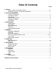
Table Of Contents PAGE 1. SAFETY SAFETY RULES FOR POWER TOOLS ..................................................................................3-4 ADDITIONAL SAFETY FOR MILLING MACHINES ....................................................................5 2. CIRCUIT REQUIREMENTS 110 VOLT OPERATION ..............................................................................................................6 EXTENSION CORDS ....................................................................................
SECTION 1: SAFETY For Your Own Safety Read Instruction Manual Before Operating This Equipment The purpose of safety symbols is to attract your attention to possible hazardous conditions. This manual uses a series of symbols and signal words which are intended to convey the level of importance of the safety messages. The progression of symbols is described below. Remember that safety messages by themselves do not eliminate danger and are not a substitute for proper accident prevention measures.
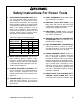
Safety Instructions For Power Tools 9. USE PROPER EXTENSION CORD. Make sure your extension cord is in good condition. Conductor size should be in accordance with the chart below. The amperage rating should be listed on the motor or tool nameplate. An undersized cord will cause a drop in line voltage resulting in loss of power and overheating. Your extension cord must also contain a ground wire and plug pin. Always repair or replace extension cords if they become damaged.
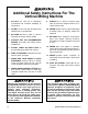
Additional Safety Instructions For The Vertical Milling Machine 1. DO NOT use until unit is completely assembled and installed according to instructions. 9. 2. DO NOT use the mill until all controls and adjustments are understood. 10. NEVER operate mill if any part is damaged or broken until it is properly repaired or replaced. 3. BE SURE drill bit or cutter is securely locked in the chuck, collet or holder. 4. ALWAYS USE THE RECOMMENDED SPEEDS and feeds with milling cutters and drill bits. 5.
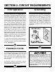
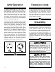
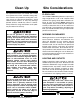
SECTION 2: CIRCUIT REQUIREMENTS 110V Operation Grounding The motor supplied with the G1004/G1008 is a dual-voltage 110/120V or 220/240V motor. (For information on operating at 220V, see the section following entitled 220V Operation.) Under normal use, the motor draws approximately 16 amps @ 110V, therefore it should be connected to a circuit that is protected by a 20 amp fuse or circuit breaker.
220V Operation Extension Cords The Model G1004/G1008 has a motor which can be operated on a 220V single phase circuit. In order to operate at 220V it is necessary to rewire the motor connections (refer to the wiring diagrams at the back of this manual) and to add a 220V capable cord and plug. The style of plug you require will depend upon the type of service you currently have or plan to install. Figure 2 shows recommended plug styles. We do not recommend the use of extension cords on 220V equipment.
SECTION 3: INTRODUCTION Commentary Most importantly, we stand behind our machines. If you have any service questions or parts requests, please call or write us at the location listed below. Grizzly Industrial, Inc. is proud to offer the Model G1004/G1008 Milling Machine. These Milling Machines are a part of Grizzly’s growing family of fine metalworking machinery. When used according to the guidelines stated in this manual, you can expect years of trouble-free, enjoyable operation.
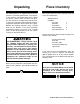
Unpacking Piece Inventory This Milling Machine is shipped from the manufacturer in a carefully packed crate. If you discover the machine is damaged after you’ve signed for delivery, and the truck and driver are gone, you will need to file a freight claim with the carrier. Save the containers and all packing materials for possible inspection by the carrier or its agent. Without the packing materials, filing a freight claim can be difficult.
Clean Up The unpainted surfaces are coated with a waxy oil to protect them from corrosion during shipment. Remove this protective coating with a solvent cleaner or citrus-based degreaser. Avoid chlorine-based solvents as they may damage painted surfaces should they come in contact. Always follow the usage instructions on the product you choose for clean up. Do not use gasoline or other petroleumbased solvents to remove this protective coating.
SECTION 4: ASSEMBLY Beginning Assembly Assembly of the G1004/G1008 is straightforward. We have organized the assembly process into steps. Please follow them in sequence. ORDER OF ASSEMBLY A. B. C. D. E. Leveling Mounting Handles Install Collet or Arbor Fly Cutter Knee Hand Crank Tools Required: A complete set of metric Allen® wrenches will be necessary for most of the assembly and adjustments. A rubber mallet and a set of open ended, metric wrenches will also be needed.
4. Turn the hex head at the top of the drawbar (located on the top, front of the head) clockwise until the threads at the bottom of the drawbar mesh with the female threads in the top of the collet or arbor. 5. When using a collet: Insert the cutter in the hole at the bottom of the collet and continue to tighten the drawbar until both the collet and cutter are tightly in place. Do not over-tighten the collet. Grasp the rim of the front pulley. Hold it tight while tightening the draw bar.
SECTION 5: OPERATIONS Test Run DO NOT attempt to investigate or adjust the machine while it is running. Wait until the machine is turned off, unplugged and all working parts have come to a rest before you do anything! Serious personal injury could occur. Speed Changes The motor is mounted on a plate hinged to the column. The motor assembly can be released by turning the handle at the side of the motor. Once the motor tension is released, the belts can be easily re-positioned to change speeds.
SECTION 6: ADJUSTMENTS Graduated Dials The graduated dials on the handwheels for the table and fine feed can be indexed or “zeroed” to help make accurate and convenient movements. Each dial can be reset or locked with the setscrew or thumb screw provided. Example: Suppose you want to drill a series of holes in a workpiece at 0.625" centers. After locating the first hole’s placement and drilling, you can set the dial of the appropriate axis to zero and move the table 0.625".
SECTION 7: MAINTENANCE General Lubrication Your Model G1004/G1008 milling machine requires very little maintenance. A thorough cleaning, now and again, will increase the machine’s durability and efficiency by removing chips and grime that can gum up moving parts. Spindle: Add oil to the oil cup after every 4 hours of use. The cup is located on the right portion of the milling head just under the belt guard. SAE 20 oil is recommended.
SECTION 8: CLOSURE Commentary The following pages contain parts diagram, parts list and Warranty/Return information for your Model G1004/1008 mill. If you need parts or help in assembling your machine, or if you need operational information, we encourage you to call our Service Department. Our trained service technicians will be glad to help you. If you have comments dealing specifically with this manual, please write to our Bellingham, Washington location using the address in Section 3 Introduction.
WARRANTY AND RETURNS Grizzly Industrial, Inc. warrants every product it sells for a period of 1 year to the original purchaser from the date of purchase. This warranty does not apply to defects due directly or indirectly to misuse, abuse, negligence, accidents, repairs or alterations or lack of maintenance.